belt JEEP CJ 1953 Owner's Manual
[x] Cancel search | Manufacturer: JEEP, Model Year: 1953, Model line: CJ, Model: JEEP CJ 1953Pages: 376, PDF Size: 19.96 MB
Page 147 of 376
'Jeep'
UNIVERSAL SERIES
SERVICE
MANUAL
Fl
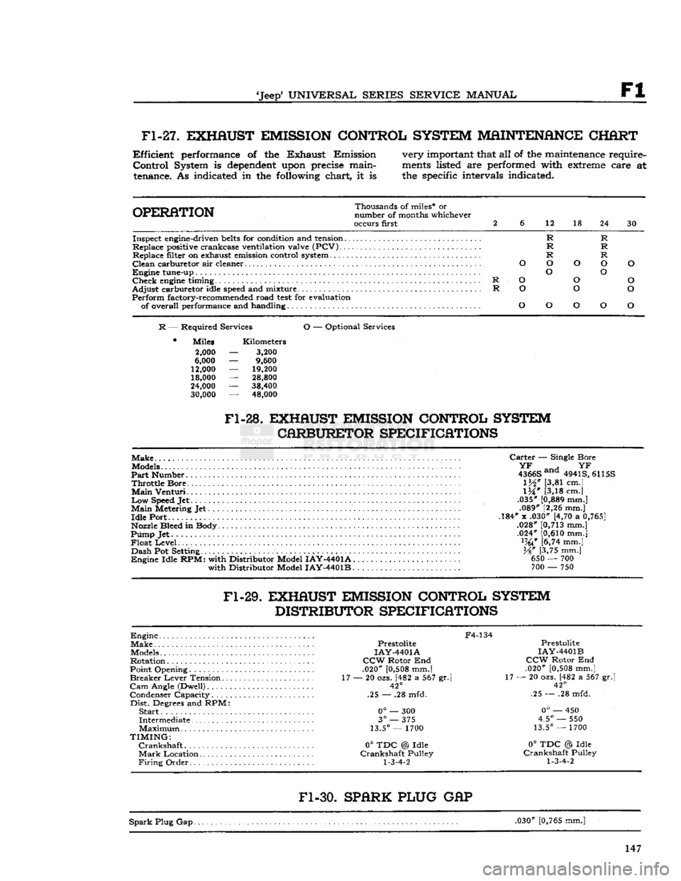
Fl-27.
EXHAUST EMISSION CONTROL SYSTEM MAINTENANCE CHART
Efficient
performance of the Exhaust Emission
Control
System is
dependent
upon precise maintenance. As indicated in the following chart, it is very important that all of the maintenance require
ments
listed are performed with extreme care at
the specific intervals indicated.
OPERATION
Thousands of miles* or
number of months whichever
occurs first 2
6
12 18
24 30
R R
R R
R R
O O o O
O
o O
R
O
o
o
R
o
o o
o
o
o
O
o
Inspect engine-driven
belts
for condition and tension...
Replace positive crankcase ventilation valve (PCV) Replace filter on exhaust emission control system
Clean
carburetor air cleaner
Engine
tune-up
Check
engine
timing
Adjust
carburetor idle
speed
and mixture
Perform
factory-recommended road
test
for evaluation of overall performance and handling
R
— Required Services
O
— Optional Services
Miles
2,000
6,000
12,000
18,000
24,000
30,000
Kilometers
3,200
9,600
19,200
28,800
38,400 48,000
Fl-28.
EXHAUST EMISSION CONTROL SYSTEM CARBURETOR SPECIFICATIONS
Make
Models
Part
Number
Throttle
Bore
Main
Venturi
Low
Speed Jet
Main
Metering Jet
Idle
Port
Nozzle Bleed in Body
Pump Jet
Float
Level
Dash
Pot Setting
Engine
Idle
RPM:
with Distributor Model
IAY-4401A.
with Distributor Model
IAY-4401B.
Carter
— Single Bore
^ an H
YF
4366S ana 4941S, 6115S
1M"
[3,81 cm.]
IX"
[3,18 cm.]
.035"
[0,889
mm.] .089" [2,26 mm.]
.184" x .030" [4,70 a
0,765]
.028"
[0,713
mm.]
.024"
[0,610
mm.] lW [6,74 mm.]
%"
[3,75 mm.] 650 — 700 700 — 750
Fl-29.
EXHAUST EMISSION CONTROL SYSTEM DISTRIBUTOR SPECIFICATIONS
Engine
Make
Models
Rotation
Point Opening
Breaker
Lever
Tension..
Cam
Angle (Dwell)
Condenser Capacity
Dist.
Degrees and RPM:
Start..
Intermediate
Maximum
TIMING:
Crankshaft
Mark
Location
Firing
Order
F4-134
Prestolite
IAY-4401A
CCW
Rotor End
.020"
[0,508
mm.|
17 — 20 ozs. [482 a 567 gr.l
42°
.25 — .28 mfd.
0°
— 300
3°
— 375
13.5°
— 1700
0°
TDC @ Idle
Crankshaft
Pulley
1-3-4-2
Prestolite
IAY-4401B
CCW
Rotor End
.020"
[0,508
mm.]
17 — 20 ozs. [482 a 567 gr.
42°
.25 — .28 mfd.
0°
— 450
4.5°
— 550
13.5°
— 1700
0°
TDC @ Idle
Crankshaft
Pulley
1-3-4-2
Fl-30.
SPARK PLUG
GAP
Spark
Plug Gap. .030"
[0,765
mm.] 147
Page 149 of 376
'Jeep'
UNIVERSAL SERIES SERVICE
MANUAL
Fl
EXHAUST
EMISSION
CONTROL
SYSTEM
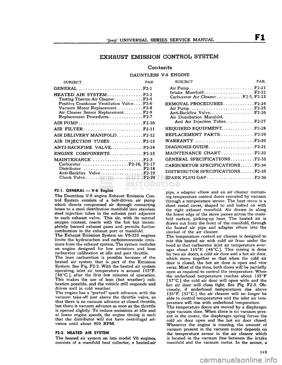
Contents
DAUNTLESS
V-6
ENGINE
SUBJECT
PAR.
GENERAL
.F2-1
HEATED
AIR
SYSTEM.
. F2-2
Testing
Thermo
Air
Cleaner
F2-4
Positive
Crankcase
Ventilation
Valve.
. . .F2-6
Vacuum
Motor Replacement . .F2-8
Air
Cleaner Sensor Replacement F2-9
Replacement Procedures F2-7
AIR
PUMP
.F2-10
AIR
FILTER.
F2-11
AIR
DELIVERY
MANIFOLD.
F2-12
AIR INJECTION TUBES.
F2-13
ANTI-BACKFIRE
VALVE..
.F2-14
ENGINE COMPONENTS
.F2-15
MAINTENANCE
.F2-3
Carburetor
F2-16, F2-17
Distributor
F2-18
Anti-Backfire
Valve . . F2-19
Check
Valve..
F2-20
F2-1.
GENERAL
—V-6
Engine
The
Dauntless V-6
engine
Exhaust
Emission
Con
trol
System consists of a belt-driven air pump
which
directs compressed air through connecting
hoses
to a steel distribution manifold into stainless steel injection
tubes
in the exhaust port adjacent
to each exhaust valve.
This
air, with its normal
oxygen
content, reacts with the hot but incom
pletely burned exhaust
gases
and permits further combustion in the exhaust port or manifold.
The
Exhaust
Emission System on V6-225
engines
limits
the hydrocarbon and carbonmonoxide emissions from the exhaust system. The system includes
an
engine
designed for low emissions and lean
carburetor
calibration at idle and part throttle.
The
lean carburetion is possible because of the
heated air system that is part of the Emission
System.
See Fig. F2-2.
With
the heated air system
operating, inlet air temperature is around
115°F.
[46°C],
after the first few minutes of operation.
This
makes the use of lean (hot weather)
cali
bration
possible, and the vehicle
still
responds and
drives
well in cold weather.
The
engine
has a "ported"
spark
advance, with the
vacuum
take-off just above the throttle valve, so that there is no vacuum advance at closed throttle,
but there is vacuum advance as
soon
as the throttle is opened slightly. To reduce emissions at idle and
at lower
engine
speeds, the
engine
timing is such
that the distributor
will
not have centrifugal ad
vance until about 900 RPM.
F2-2.
HEATED
AIR
SYSTEM
The
heated air system on late model V6 engines,
consists of a manifold heat collector, a heated-air
SUBJECT
PAR.
Air
Pump F2-21
Intake
Manifold F2-22
Carburetor
Air Cleaner F2-5, F2-23
REMOVAL PROCEDURES
F2-24
Air
Pump. F2-25
Anti-Backfire
Valve..
. . .F2-26
Air
Distribution Manifold,
And
Air Injection Tubes F2-27
REQUIRED
EQUIPMENT..
. F2-28
REPLACEMENT
PARTS..
.F2-29
WARRANTY
F2-30
DIAGNOSIS GUIDE
F2-31
MAINTENANCE CHART.
F2-32
GENERAL
SPECIFICATIONS
F2-33
CARBURETOR SPECIFICATIONS.
.... .F2-34
DISTRIBUTOR SPECIFICATIONS
. .F2-35
SPARK PLUG GAP
F2-36
pipe, a adapter elbow and an air cleaner containing temperature control doors operated by vacuum
through a temperature sensor. The heat
stove
is a
sheet
metal cover, shaped to and bolted on with
the right exhaust manifold. Air drawn in along the lower
edge
of the
stove
passes across the mani
fold surface, picking-up heat. The heated air is
drawn
out from the front of the manifold, through
the heated air pipe and adapter elbow into the
snorkel
of the air cleaner.
The
temperature control air cleaner is designed to mix this heated air with cold air from under the
hood so that carburetor inlet air temperature aver
ages
about
115°F.
[46°C.].
This
mixing is
done
by two air doors, a cold air door and a hot air door,
which
move
together
so that when the cold air door is closed, the hot air door is open and vice
versa.
Most of the time, both doors
will
be partially
open as required to control the temperature. When
the underhood temperature reaches about 135
°F
[57°C]
the cold air door
will
open wide and the
hot air door
will
close
tight See Fig. F2-3. Ob viously, if underhood temperatures rise above
135°F.
[57°C]
the air cleaner
will
no longer be
able to control temperatures and the inlet air tem
perature
will
rise with underhood temperature.
The
temperature doors are moved by a diaphragm
type vacuum door. When there is no vacuum pres ent in the motor, the diaphragm spring forces the
cold air door open and the hot air door closed.
Whenever
the
engine
is running, the amount of
vacuum
present in the vacuum motor depends on
the temperature sensor in the air cleaner which is located in the vacuum line
between
the intake
manifold and the vacuum motor. In the sensor, a 149
Page 156 of 376
F2
EXHAUST EMISSION CONTROL SYSTEMS
the throttle
stop
screw to idle the
engine
at 650
to 700 rpm.
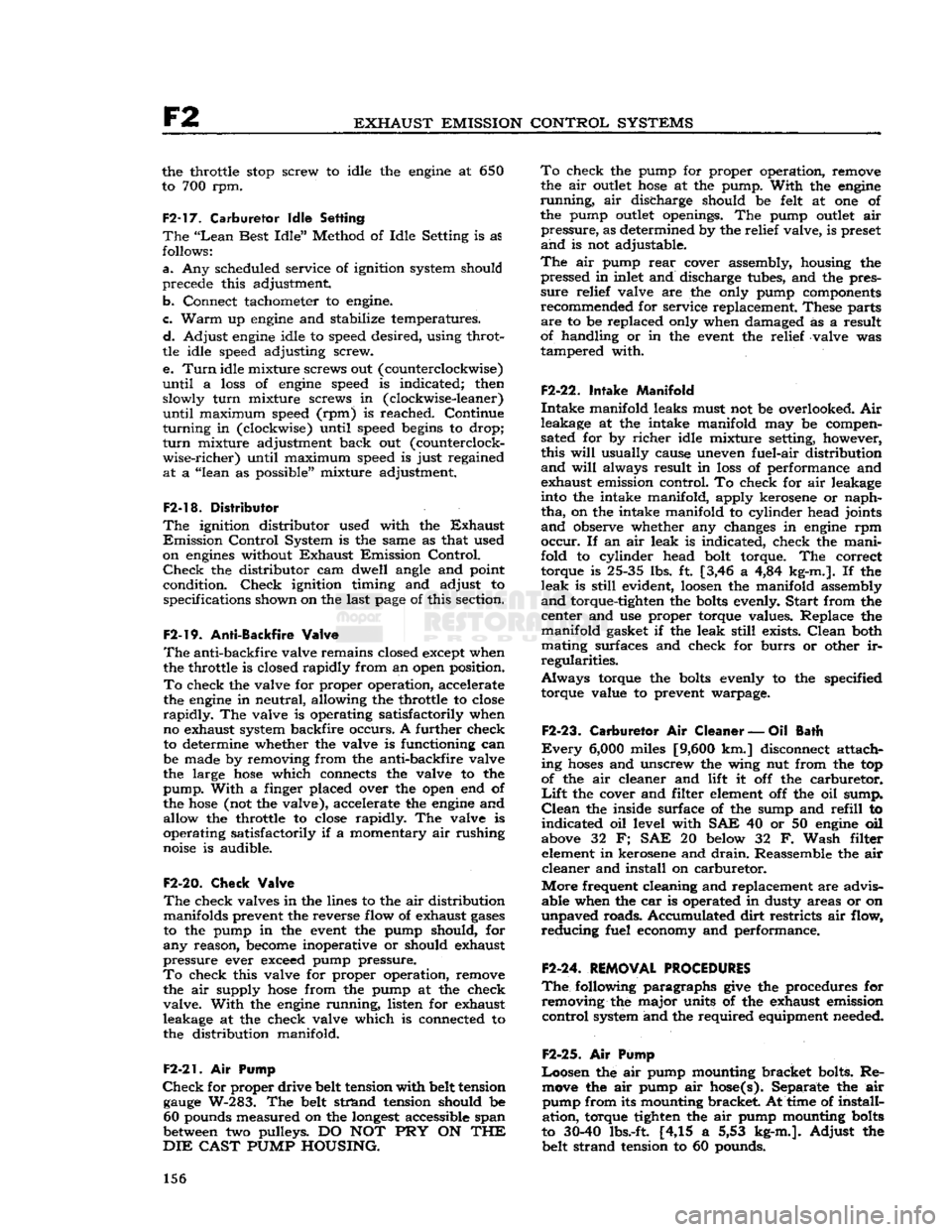
F2-17. Carburetor Idle Setting
The
"Lean
Best
Idle"
Method of Idle Setting is as
follows:
a.
Any scheduled service of ignition system should
precede this adjustment
b.
Connect tachometer to engine.
c.
Warm
up
engine
and stabilize temperatures.
d.
Adjust
engine
idle to speed desired, using throt
tle idle speed adjusting screw.
e.
Turn
idle mixture screws out (counterclockwise)
until
a
loss
of
engine
speed is indicated; then slowly
turn
mixture screws in (clockwise-leaner)
until
maximum speed (rpm) is reached. Continue
turning
in (clockwise) until speed begins to drop;
turn
mixture adjustment back out (counterclock
wise-richer)
until maximum speed is just regained
at
a "lean as possible" mixture adjustment.
F2-18. Distributor
The
ignition distributor used with the
Exhaust
Emission
Control
System is the same as that used
on
engines
without
Exhaust
Emission
Control.
Check
the distributor cam dwell angle and point
condition.
Check
ignition timing and adjust to specifications shown on the last
page
of this section.
F2-19.
Anti-Backfire
Valve
The
anti-backfire valve remains closed except when
the throttle is closed rapidly from an open position.
To
check the valve for proper operation, accelerate
the
engine
in neutral, allowing the throttle to close
rapidly.
The valve is operating satisfactorily when
no exhaust system backfire occurs. A further check
to determine whether the valve is functioning can
be made by removing from the anti-backfire valve
the large
hose
which connects the valve to the
pump.
With
a finger placed over the open end of
the
hose
(not the valve), accelerate the
engine
and allow the throttle to close rapidly. The valve is
operating satisfactorily if a momentary air rushing
noise is audible.
F2-20.
Check
Valve
The
check valves in the lines to the air distribution manifolds prevent the reverse flow of exhaust
gases
to the pump in the event the pump should, for
any
reason,
become
inoperative or should exhaust
pressure
ever exceed pump pressure.
To
check this valve for proper operation, remove the air supply
hose
from the pump at the check
valve.
With
the
engine
running, listen for exhaust
leakage at the check valve which is connected to
the distribution manifold.
F2-21.
Air
Pump
Check
for proper drive belt tension with belt tension
gauge
W-283. The belt strand tension should be 60 pounds measured on the
longest
accessible span
between two pulleys. DO NOT PRY ON THE
DIE
CAST
PUMP
HOUSING. To
check the pump for proper operation, remove
the air
outlet
hose
at the pump.
With
the
engine
running,
air discharge should be felt at one of
the pump
outlet
openings. The pump
outlet
air
pressure,
as determined by the relief valve, is preset
and
is not adjustable.
The
air pump
rear
cover assembly, housing the pressed in inlet and discharge tubes, and the pres
sure
relief valve are the only pump components
recommended for service replacement. These parts
are
to be replaced only when damaged as a result
of handling or in the event the relief valve was
tampered with.
F2-22.
Intake Manifold
Intake
manifold leaks must not be overlooked. Air
leakage at the intake manifold may be compen
sated for by
richer
idle mixture setting, however, this
will
usually cause uneven fuel-air distribution
and
will
always result in
loss
of performance and
exhaust emission control. To check for air leakage
into the intake manifold, apply kerosene or naph
tha,
on the intake manifold to cylinder head joints
and
observe whether any changes in
engine
rpm
occur.
If an air leak is indicated, check the mani
fold to cylinder head bolt torque. The correct torque is 25-35 lbs. ft. [3,46 a 4,84 kg-m.]. If the
leak
is
still
evident,
loosen
the manifold assembly
and
torque-tighten the bolts evenly.
Start
from the center and use proper torque values. Replace the
manifold
gasket if the leak
still
exists.
Clean
both
mating surfaces and check for
burrs
or other ir
regularities.
Always
torque the bolts evenly to the specified
torque value to prevent warpage.
F2-23.
Carburetor
Air
Cleaner
—Oil
Bath
Every
6,000
miles [9,600 km.] disconnect attach
ing
hoses
and unscrew the wing nut from the top
of the air cleaner and lift it off the carburetor.
Lift
the cover and filter element off the oil sump.
Clean
the inside surface of the sump and
refill
to
indicated
oil level with SAE 40 or 50
engine
oil
above 32 F; SAE 20 below 32 F.
Wash
filter element in kerosene and
drain.
Reassemble the air
cleaner
and install on carburetor.
More
frequent cleaning and replacement are advis able when the car is operated in dusty areas or on
unpaved
roads. Accumulated
dirt
restricts air flow,
reducing
fuel economy and performance.
F2-24.
REMOVAL PROCEDURES
The
following paragraphs
give
the procedures for removing the major units of the exhaust emission
control
system and the required equipment needed.
F2-2S.
Air
Pump
Loosen
the air pump mounting bracket bolts. Re move the air pump air hose(s). Separate the air pump from its mounting bracket. At time of install
ation,
torque tighten the air pump mounting bolts
to
30-40
lbs.-ft [4,15 a 5,53 kg-m.].
Adjust
the
belt strand tension to 60 pounds. 156
Page 158 of 376
F2
EXHAUST EMISSION CONTROL SYSTEMS
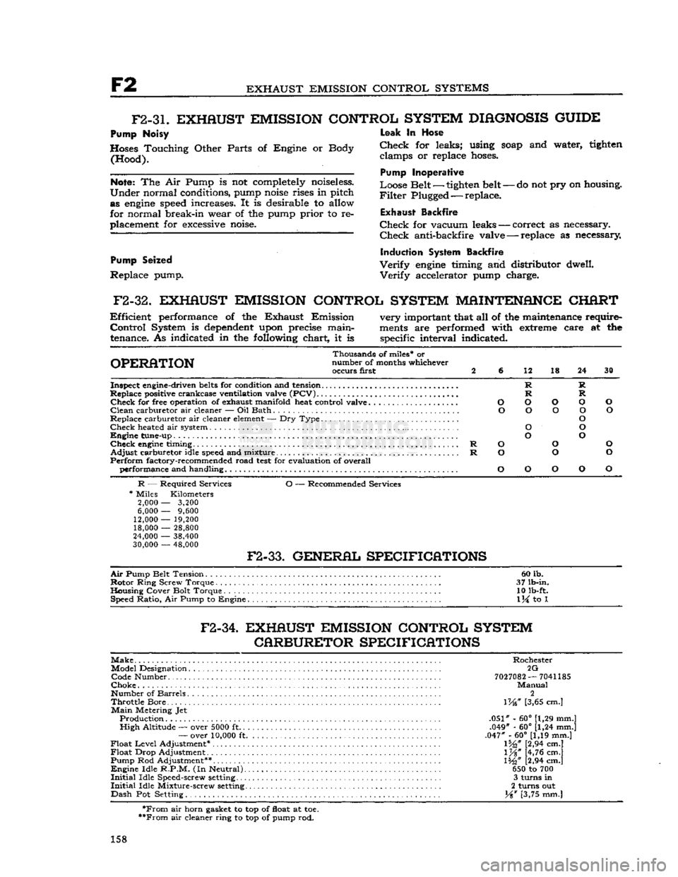
F2-3L
EXHAUST EMISSION CONTROL SYSTEM
DIAGNOSIS
GUIDE
Pump Noisy
Hoses Touching Other Parts of Engine or Body (Hood).
Note:
The Air Pump is not completely noiseless.
Under
normal conditions, pump
noise
rises in pitch as
engine
speed
increases. It is desirable to allow
for normal break-in wear of the pump prior to re
placement for
excessive
noise.
Pump Seized
Replace pump.
-
do not pry on housing.
Leak
In Hose
Check
for leaks; using
soap
and water, tighten clamps or replace
hoses.
Pump Inoperative
Loose Belt — tighten belt
-
Filter
Plugged — replace.
Exhaust
Backfire
Check
for vacuum leaks — correct as necessary.
Check
anti-backfire valve — replace as necessary
Induction System Backfire
Verify
engine
timing and distributor dwell.
Verify
accelerator pump charge.
F2-32.
EXHAUST EMISSION CONTROL SYSTEM MAINTENANCE CHART
Efficient
performance of the Exhaust Emission very important that all of the maintenance require-
Control
System is
dependent
upon precise main-
ments
are performed with extreme care at the
tenance. As indicated in the following chart, it is specific interval indicated.
Thousands of miles* or
OPERATION
number of months whichever occurs first 2 6 12 18 24 30
Inspect engine-driven
belts
for condition and tension R R
Replace positive crankcase ventilation valve
(PCV)
R R
Check
for free operation of exhaust manifold heat control valve O O O O O
Clean
carburetor air cleaner — Oil Bath O O O O O
Replace carburetor air cleaner
element
— Dry Type O
Check
heated air system O O
Engine
tune-up O O
Check
engine
timing R O O O
Adjust
carburetor idle
speed
and mixture R O O O
Perform
factory-recommended road
test
for evaluation of overall performance and handling O O O O O
R
— Required Services O — Recommended Services
*
Miles Kilometers
2,000
—
3,200
6,000
—
9,600
12,000
—
19,200 18,000
—
28,800
24,000
—
38,400
30,000
—
48,000
F2-33.
GENERAL SPECIFICATIONS
Air
Pump Belt Tension 60 lb.
Rotor
Ring Screw Torque . 37 lb-in.
Housing Cover Bolt Torque 10 lb-ft. Speed Ratio, Air Pump to Engine
1
\i to 1
F2-34.
EXHAUST EMISSION CONTROL SYSTEM CARBURETOR SPECIFICATIONS
Make
Rochester Model Designation 2G Code Number
7027082
—
7041185
Choke
Manual
Number of Barrels 2
Throttle
Bore... \W [3,65 cm.]
Main
Metering Jet Production .051" - 60° [1,29 mm.]
High
Altitude — over
5000
ft .049" - 60° [1,24 mm.]
—
over
10,000
ft .047" - 60° [1,19 mm.]
Float
Level
Adjustment* 1%," [2,94 cm.]
Float
Drop Adjustment l%" [4,76 cm.]
Pump Rod Adjustment** 1%" [2,94 cm.]
Engine
Idle
R.P.M.
(In Neutral) 650 to 700
Initial
Idle Speed-screw
setting
3 turns in
Initial
Idle Mixture-screw
setting
2 turns out
Dash
Pot Setting. Y%w [3,75 mm.]
*From
air horn gasket to top of float at toe.
**From
air cleaner ring to top of pump rod.
158
Page 161 of 376
'Jeep*
UNIVERSAL
SERIES
SERVICE
MANUAL
COOLING
SYSTEM
Contents
SUBJECT
PAR.
GENERAL
.G-l Antifreeze Solutions. .G-l6
Cylinder
Block.
..................
.G-8
Draining
Cooling System............... G-3
Engine
Overheating..
.................
.G-19
Fan
Belt.
......... .........
.G-18
Filling
Cooling System.................
G-2
Inhibited
Coolant Solution .G-l7
Temperature
Sending Unit.
...........
.G-l0
Thermostat
.........................
G-9
RADIATOR
.G-5
Radiator
and Heater Hoses.............
G-7
SUBJECT
PAR.
Radiator
Pressure
Cap.................
G-4
Radiator
Removal and Replacement..... G-6
WATER
PUMP.
. . .G-ll
Water
Pump Disassembly. .............G-13
Water
Pump Inspection.
..............
.G-12
Water
Pump Reassembly.
.............
.G-14
Water
Pump Removal and Replacement. .G-l5
SERVICE
DIAGNOSIS.
.G-20
SPECIFICATIONS
. .G-21
ANTIFREEZE
CHART.
..... ... .G-22
G-l. GENERAL
a.
The satisfactory performance of the Hurricane
F4
engine
is controlled to a great
extent
by the proper operation of the cooling system. The
engine
block is full length water jacketed which prevents
distortion of the cylinder walls. Directed cooling
and
large water holes, properly placed in the cylin
der head gasket cause more water to flow past the
valve
seats
(which are the
hottest
parts of the
block)
and
carry
the heat away from the valves, giving positive cooling of valves and seats.
Minimum
temperature of the coolant is controlled by a thermostat mounted in the
outlet
passage of
the engine. When the coolant temperature is below
thermostat-rated temperature, the thermostat re mains closed and the coolant is directed through
the radiator-bypass
hose
to the water pump. When the thermostat opens, coolant flow is directed to
the top of the radiator. The radiator dissipates the
excess
engine
heat before the coolant is recirculated
through the engine.
The
cooling system is pressurized. Operating pres
sure
is regulated by the rating of the radiator cap
which
contains a relief valve, b. The Dauntless V-6
engine
efficiency and performance is controlled to a great
extent
by proper
operation of the cooling system. The cooling system
does
more than cool the engine. It also directs
the flow of coolant to provide the
best
operating
temperature range for each part of the engine.
In
the Dauntless V-6
engine
coolant is forced by
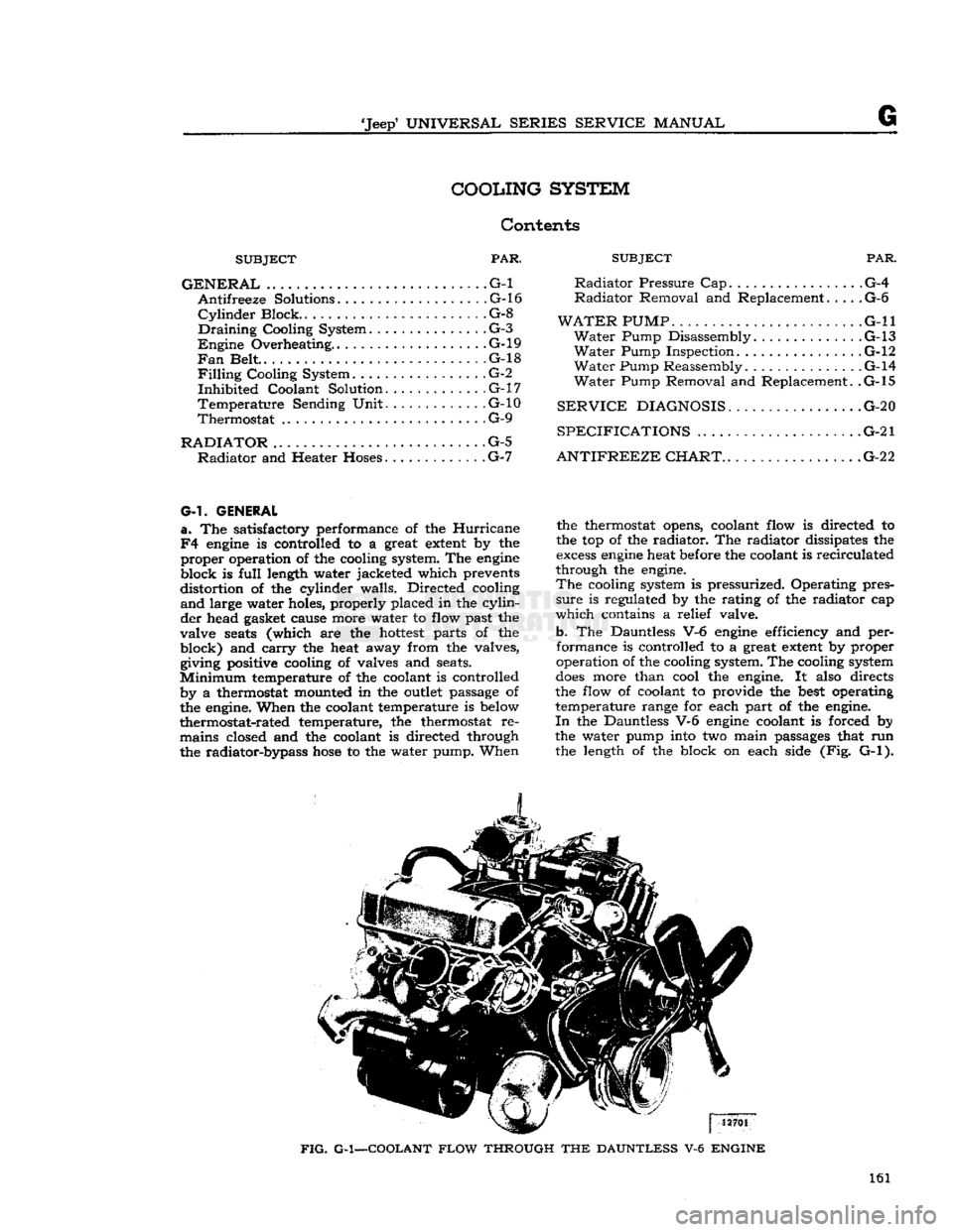
the water pump into two main passages that run the length of the block on each side (Fig. G-l).
FIG.
G-1—COOLANT
FLOW
THROUGH
THE
DAUNTLESS
V-6
ENGINE
161
Page 162 of 376
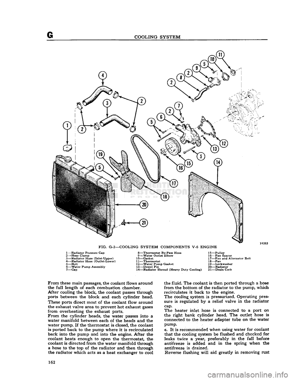
COOLING
SYSTEM
14263
FIG.
G-2—COOLING SYSTEM
COMPONENTS
V-6
ENGINE
1—
Radiator
Pressure Cap
2—
Hose
Clamp
3—
Radiator
Hose (Inlet-Upper)
4—
Radiator
Hose (Outlet-Lower) 5—
Bolt
6—
Water
Pump Assembly 7—
Cap
8—Thermostat
By-Pass Hose
g—Water Outlet
Elbow
10—
Gasket
11—
Thermostat
12—
Water
Pump Gasket
13—
Dowel
Pin
14—
Radiator
Shroud (Heavy Duty Cooling) 15—
Pulley
16—
Fan
Spacer
17—
Fan
and Alternator Belt
18—Fan
19—
Lockwasher
20—
Radiator
21—
Drain
Cock
From
these
main passages, the coolant flows around
the
full
length of each combustion chamber.
After
cooling the block, the coolant passes through
ports between the block and each cylinder head.
These
ports direct most of the coolant flow around the exhaust valve area to prevent hot exhaust
gases
from
overheating the exhaust ports.
From
the cylinder heads, the water passes into a
water
manifold between each of the heads and the
water
pump. If the thermostat is closed, the coolant
is ported back to the pump where it is recirculated
back
into the pump and into the engine. After the
coolant heats enough to open the thermostat, the coolant is directed from the water manifold through
a
hose
to the top of the radiator and then through
the radiator which acts as a heat exchanger to cool the fluid. The coolant is then ported through a
hose
from
the bottom of the radiator to the pump, which
recirculates
it back to the engine.
The
cooling system is pressurized. Operating pres
sure
is regulated by a relief valve in the radiator
cap. The
heater inlet
hose
is connected to a port on
the right bank cylinder head. The outlet
hose
is connected to the heater adapter tube on the water
pump.
c.
It is recommended when using water for coolant
that the cooling system be flushed and checked for leaks twice a year, preferably in the
fall
before
antifreeze is added and in the spring when the antifreeze is drained.
Reverse
flushing
will
aid greatly in removing rust 162
Page 167 of 376
'Jeep*
UNIVERSAL
SERIES
SERVICE
MANUAL
FIG.
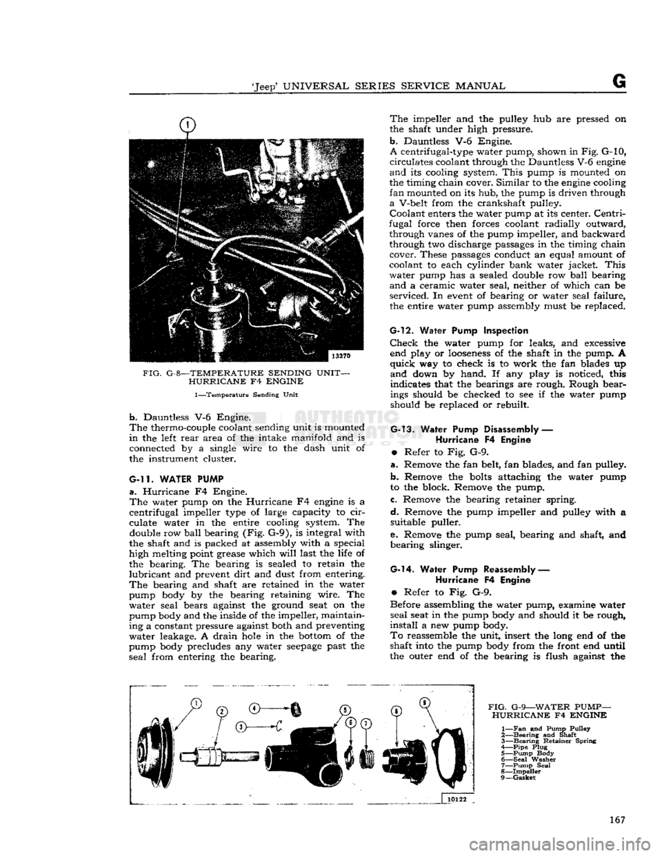
G-8—TEMPERATURE SENDING UNIT- HURRICANE
F4
ENGINE
1—Temperature
Sending Unit
b.
Dauntless V-6 Engine.
The
thermo-couple coolant sending unit is mounted
in
the left
rear
area of the intake manifold and is
connected by a single wire to the dash unit of
the instrument cluster.
G-ll.
WATER PUMP
a.
Hurricane
F4 Engine.
The
water pump on the
Hurricane
F4
engine
is a
centrifugal
impeller type of large capacity to
cir
culate water in the entire cooling system. The double row
ball
bearing (Fig. G-9), is integral with
the shaft and is packed at assembly with a special
high melting point grease which
will
last the life of
the bearing. The bearing is sealed to retain the
lubricant
and prevent
dirt
and dust from entering.
The
bearing and shaft are retained in the water
pump body by the bearing retaining wire. The
water
seal bears against the ground seat on the
pump body and the inside of the impeller, maintain
ing a constant pressure against both and preventing
water
leakage. A
drain
hole
in the
bottom
of the
pump body precludes any water
seepage
past the
seal
from entering the bearing.
The
impeller and the pulley hub are pressed on
the shaft under high pressure,
b.
Dauntless V-6 Engine.
A
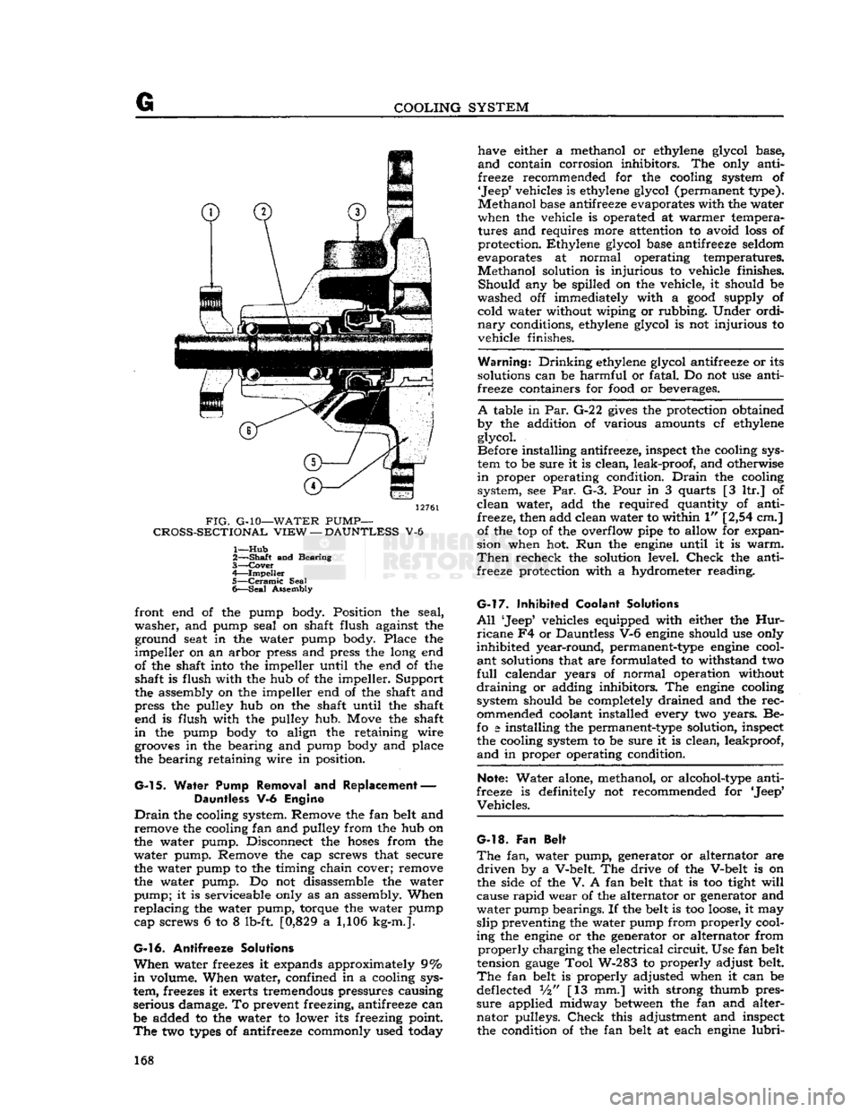
centrifugal-type water pump, shown in
Fig.
G-10,
circulates
coolant through the Dauntless V-6
engine
and
its cooling system.
This
pump is mounted on
the timing chain cover.
Similar
to the
engine
cooling
fan
mounted on its hub, the pump is driven through
a
V-belt from the crankshaft pulley.
Coolant
enters the water pump at its center.
Centri
fugal force then forces coolant radially outward, through vanes of the pump impeller, and backward
through two discharge passages in the timing chain cover. These passages conduct an equal amount of
coolant to each cylinder bank water jacket.
This
water
pump has a sealed double row
ball
bearing
and
a ceramic water seal, neither of which can be
serviced.
In
event
of bearing or water seal failure, the entire water pump assembly must be replaced.
G-l2.
Water
Pump Inspection
Check
the water pump for leaks, and excessive end play or
looseness
of the shaft in the pump. A
quick
way to check is to work the fan blades up
and
down by hand. If any play is noticed, this
indicates that the bearings are rough. Rough bearings should be checked to see if the water pump
should be replaced or rebuilt.
G-13.
Water Pump
Disassembly
—
Hurricane
F4
Engine
•
Refer to Fig. G-9.
a.
Remove the fan belt, fan blades, and fan pulley.
b.
Remove the
bolts
attaching the water pump
to the block. Remove the pump.
c.
Remove the bearing retainer spring.
d.
Remove the pump impeller and pulley with a suitable puller.
e.
Remove the pump seal, bearing and shaft, and
bearing
slinger.
G-l4.
Water Pump Reassembly
—
Hurricane
F4
Engine
•
Refer to Fig. G-9.
Before assembling the water pump, examine water
seal
seat in the pump body and should it be rough,
install
a new pump body.
To
reassemble the unit, insert the long end of the shaft into the pump body from the front end until
the outer end of the bearing is flush against the
FIG.
G-9—WATER
PUMP-
HURRICANE
F4
ENGINE
1—
Fan
and Pump Pulley
2—
Bearing
and Shaft
3—
Bearing
Retainer Spring
A—Pipe
Plug 5—
Pump
Body
6—
Seal
Washer 7—
Pump
Seal
8—
Impeller
9—
Gasket
167
Page 168 of 376
G
COOLING SYSTEM
12761
FIG.
G-10—WATER
PUMP—
CROSS-SECTIONAL
VIEW
—
DAUNTLESS
V-6
1—
Hub
2—
—Shaft
and Bearing
3—
Cover
4—
Impeller
5—
Ceramic
Seal
6—
Seal
Assembly front end of the pump body. Position the seal,
washer,
and pump seal on shaft flush against the ground seat in the water pump body. Place the
impeller
on an arbor press and press the long end
of the shaft into the impeller until the end of the shaft is flush with the hub of the impeller. Support
the assembly on the impeller end of the shaft and
press the pulley hub on the shaft until the shaft end is flush with the pulley hub. Move the shaft
in
the pump body to align the retaining wire
grooves
in the bearing and pump body and place
the bearing retaining wire in position.
G-l
5. Water Pump Removal and Replacement — Dauntless V-6 Engine
Drain
the cooling system. Remove the fan belt and remove the cooling fan and pulley from the hub on
the water pump. Disconnect the
hoses
from the
water
pump. Remove the cap screws that secure
the water pump to the timing chain cover; remove
the water pump. Do not disassemble the water
pump;
it is serviceable only as an assembly. When
replacing
the water pump, torque the water pump cap screws 6 to 8 lb-ft. [0,829 a 1,106 kg-m.].
G-16.
Antifreeze Solutions
When
water freezes it expands approximately 9%
in
volume. When water, confined in a cooling sys
tem, freezes it exerts tremendous pressures causing
serious damage. To prevent freezing, antifreeze can
be added to the water to lower its freezing point.
The
two
types
of antifreeze commonly used today have either a methanol or ethylene glycol base,
and
contain corrosion inhibitors. The only anti
freeze recommended for the cooling system of
'Jeep'
vehicles is ethylene glycol (permanent type).
Methanol
base antifreeze evaporates with the water
when the vehicle is operated at warmer tempera
tures and requires more attention to avoid
loss
of
protection. Ethylene glycol base antifreeze seldom
evaporates at normal operating temperatures.
Methanol
solution is injurious to vehicle finishes.
Should
any be spilled on the vehicle, it should be
washed off immediately with a
good
supply of cold water without wiping or rubbing. Under ordi
nary
conditions, ethylene glycol is not injurious to
vehicle finishes.
Warning.*
Drinking
ethylene glycol antifreeze or its
solutions can be harmful or fatal. Do not use anti
freeze containers for
food
or beverages.
A
table in Par.
G-2
2
gives
the protection obtained
by the addition of various amounts cf ethylene glycol.
Before installing antifreeze, inspect the cooling sys
tem to be sure it is clean, leak-proof, and otherwise
in
proper operating condition.
Drain
the cooling system, see Par. G-3. Pour in 3 quarts [3 ltr.] of
clean
water, add the required quantity of anti freeze, then add clean water to within 1" [2,54 cm.] of the top of the overflow pipe to allow for expan
sion when hot. Run the
engine
until it is
warm.
Then
recheck the solution level.
Check
the anti
freeze protection with a hydrometer reading.
G-l7.
Inhibited Coolant Solutions
All
'Jeep5 vehicles equipped with either the
Hur
ricane
F4 or Dauntless V-6
engine
should use only
inhibited
year-round, permanent-type
engine
cool
ant
solutions that are formulated to withstand two
full
calendar years of normal operation without
draining
or adding inhibitors. The
engine
cooling
system should be completely drained and the
rec
ommended coolant installed every two years. Be-
fo
a
installing the permanent-type solution, inspect the cooling system to be sure it is clean, leakproof,
and
in proper operating condition.
Note:
Water alone, methanol, or alcohol-type anti
freeze is definitely not recommended for 'Jeep*
Vehicles.
G-l8.
Fan Belt
The
fan, water pump, generator or alternator are
driven
by a V-belt. The drive of the V-belt is on
the side of the V. A fan belt that is too tight
will
cause
rapid
wear of the alternator or generator and
water
pump bearings. If the belt is too
loose,
it may
slip
preventing the water pump from properly cool
ing the
engine
or the generator or alternator from
properly
charging the electrical
circuit.
Use fan belt
tension
gauge
Tool W-283 to properly adjust belt.
The
fan belt is properly adjusted when it can be
deflected Vi" [13 mm.] with strong thumb pres
sure
applied midway
between
the fan and alter
nator
pulleys.
Check
this adjustment and inspect the condition of the fan belt at each
engine
lubri-
168
Page 169 of 376
'Jeep'
UNIVERSAL
SERIES SERVICE
MANUAL
G
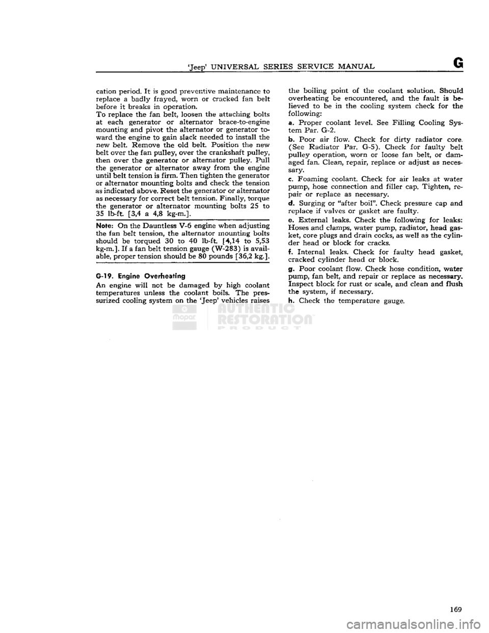
cation period. It is
good
preventive maintenance to
replace a badly frayed, worn or cracked fan belt
before it breaks in operation.
To
replace the fan belt,
loosen
the attaching
bolts
at each generator or alternator brace-to-engine mounting and pivot the alternator or generator to
ward
the
engine
to gain slack needed to install the new belt Remove the old belt. Position the new
belt over the fan pulley, over the crankshaft pulley,
then over the generator or alternator pulley.
Pull
the generator or alternator away from the
engine
until
belt tension is
firm.
Then tighten the generator
or
alternator mounting
bolts
and check the tension
as indicated above. Reset the generator or alternator as necessary for correct belt tension.
Finally,
torque
the generator or alternator mounting
bolts
25 to 35 lb-ft. [3,4 a 4,8 kg-m.].
Note:
On the Dauntless V-6
engine
when adjusting
the fan belt tension, the alternator mounting
bolts
should be torqued 30 to 40 lb-ft. [4,14 to 5,53
kg-m.].
If a fan belt tension
gauge
(W-283) is
avail
able, proper tension should be 80 pounds [36,2 kg.].
G-l
9. Engine Overheating
An
engine
will
not be damaged by high coolant
temperatures unless the coolant boils. The pres
surized
cooling system on the 'Jeep' vehicles raises the boiling point of the coolant solution. Should
overheating be encountered, and the fault is be
lieved to be in the cooling system check for the
following:
a.
Proper coolant level. See
Filling
Cooling Sys
tem Par. G-2.
b. Poor air flow.
Check
for dirty radiator core. (See Radiator Par. G-5).
Check
for faulty belt
pulley operation, worn or
loose
fan belt, or dam aged fan.
Clean,
repair, replace or adjust as neces
sary.
c. Foaming coolant.
Check
for air leaks at water
pump,
hose
connection and filler cap. Tighten, re
pair
or replace as necessary.
d.
Surging or "after boil".
Check
pressure cap and
replace if valves or gasket are faulty.
e.
External
leaks.
Check
the following for leaks:
Hoses and clamps, water pump, radiator, head gas
ket, core plugs and drain cocks, as well as the cylin der head or block for
cracks.
f.
Internal
leaks.
Check
for faulty head gasket,
cracked
cylinder head or block.
g. Poor coolant flow.
Check
hose
condition, water pump, fan belt, and repair or replace as necessary. Inspect block for rust or scale, and clean and flush
the system, if necessary.
h.
Check
the temperature
gauge.
169
Page 170 of 376
G
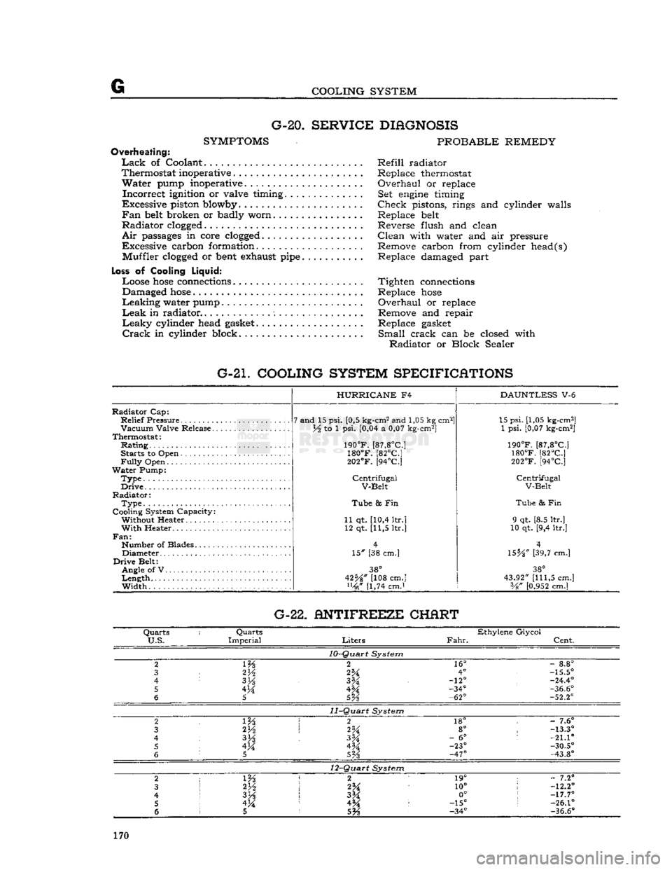
COOLING SYSTEM G-20.
SERVICE DIAGNOSIS
SYMPTOMS
PROBABLE REMEDY
Overheating:
Lack
of Coolant Refill radiator
Thermostat inoperative . Replace thermostat
Water
pump inoperative. Overhaul or replace
Incorrect
ignition or valve timing. Set
engine
timing
Excessive piston blowby Check pistons, rings and cylinder walls
Fan
belt
broken or badly worn Replace
belt
Radiator
clogged
Reverse flush and clean
Air
passages
in core
clogged
Clean with water and air pressure
Excessive carbon formation. Remove carbon from cylinder head(s) Muffler
clogged
or
bent
exhaust
pipe
Replace damaged part
Loss
of Cooling
Liquid:
Loose
hose
connections
Tighten
connections
Damaged
hose
Replace
hose
Leaking
water pump Overhaul or replace
Leak
in radiator Remove and repair
Leaky
cylinder head
gasket
Replace
gasket
Crack
in cylinder block. Small crack can be closed with
Radiator
or Block Sealer
G-21. COOLING SYSTEM SPECIFICATIONS
Radiator
Cap:
Relief
Pressure
Vacuum
Valve Release.
Thermostat:
Rating
Starts to Open
Fully
Open
Water
Pump:
Type.
Drive
Radiator:
Type
Cooling System Capacity: Without Heater
With
Heater..
Fan:
Number of Blades Diameter
Drive
Belt: Angle of V
Length
Width
HURRICANE
F4
7 and 15 psi. [0,5 kg-cm2 and 1,05 kg cm2]
lA to 1 psi. [0,04 a 0,07 kg-cm2]
190°F.
[87,8°C]
180°F.
[82°C]
202°F.
[94°C]
Centrifugal
V-Belt
Tube
8s Fin
11 qt. [10,4 ltr.] 12 qt. [11,5 ltr.]
15" [38 cm.]
38°
42%" [108 cm.] [1,74 cmJ
DAUNTLESS
V-6 15 psi. [1,05 kg-cm2]
1 psi. [0,07 kg-cm2]
190°F.
[87,8°C]
180°F.
[82°C]
202°F.
[94°C]
Centrifugal
V-Belt
Tube
& Fin
9 qt. [8.5 ltr.]
10 qt. [9,4 ltr.]
4
\SbA"
[39,7 cm.]
38°
43.92"
[111,5
cm.] Vg"
[0.952
cm.] G-22. ANTIFREEZE CHERT
Quarts
i
Quarts
Ethylene Glycol
U.S.
Imperial
Liters
Fahr.
Cent.
10-Quart
System
2
m
2
16°
-
8.8°
3
2V2
2%
4°
-15.5°
4
3H
-12°
-24.4°
5 4M -34°
-36.6°
6
5
5Vs
-62°
-52.2°
11-Quart
System
2 2
18° -
7.6°
3 2H
2%
8°
-13.3°
4
3%
-
6°
:
-21.10
5 4M 4M -23°
-30.5°
6
5
SVs
-47°
-43.8°
12-Quart
System
2
1 m 2 1
19° ;
- 7.2°
3
2*A
10°
!
-12.2°
4
I
3H
3M 0°
;
-17.7°
5 !
4M 4^ :
-15°
s
-26.1°
6 1 5
5%
-34°
-36.6°
170