clock JEEP CJ 1953 User Guide
[x] Cancel search | Manufacturer: JEEP, Model Year: 1953, Model line: CJ, Model: JEEP CJ 1953Pages: 376, PDF Size: 19.96 MB
Page 67 of 376
'Jeep'
UNIVERSAL
SERIES SERVICE
MANUAL
D
Lubricate
the connecting rod bearing surfaces
generously with
engine
oil and install the bearing
cap with the numbered side matched to the num
bered side of the connecting rod. Torque the nuts
evenly 35 to 45 lb-ft. [4,8 a 6,2 kg-m.]. The con
necting rod cap nuts are locked with stamped nuts.
Used
stamped nuts should be discarded and re
placed with new
ones.
These locking stamped nuts
should be installed with the flat face toward the
connecting rod nut.
Turn
the locking nut finger
tight and then 34
turn
more with a wrench. Refer
to Par. D-36 for detailed information on fitting pistons and rings in the cylinder bores.
D-96.
Install
Crankshaft
Pulley
Align
the keyway in the pulley with the woodruff key installed in the crankshaft. Drive the pulley
onto
the crankshaft and secure it in place with
the crankshaft pulley nut. Insert a block of wood
between
one of the counterweights on the
crank
shaft and the side of the cylinder block to prevent the crankshaft from turning, then tighten the nut.
D-97.
Install
Oil Pan
Before installing the oil pan, make a final internal
inspection particularly making certain that the
inside of the cylinder block is clean. Apply a thin
coat of gasket paste on the oil pan. Place the new
oil
pan gasket in position. Set the oil pan in posi
tion on the cylinder block and install the oil pan.
Torque
the attaching
bolts
12 to 15 lb-ft. [1,7 a 2,1
kg-m.].
Install
the oil pan
drain
plug and gasket
and
tighten the plug securely.
D-98.
Install
Cylinder
Head
Make
certain that the entire top of the cylinder
block
assembly, the lower surface of the cylinder
head,
and the cylinder head gasket are clean. Blow
all
dirt
or carbon out of the blind tapped bolt
holes
in
the cylinder block before the cylinder head and gasket are installed. Using aerosol spray sealer
Part
No. 994757, spray a thincoat on both surfaces
of the head gasket, position the new cylinder head gasket with the crimped
edges
of the gasket metal down (See Fig. D-31).
This
gasket position allows a
positive seal along the narrow surfaces of the
cylin
der
head
between
the combustion chambers and
eliminates the possibility of burning combustion
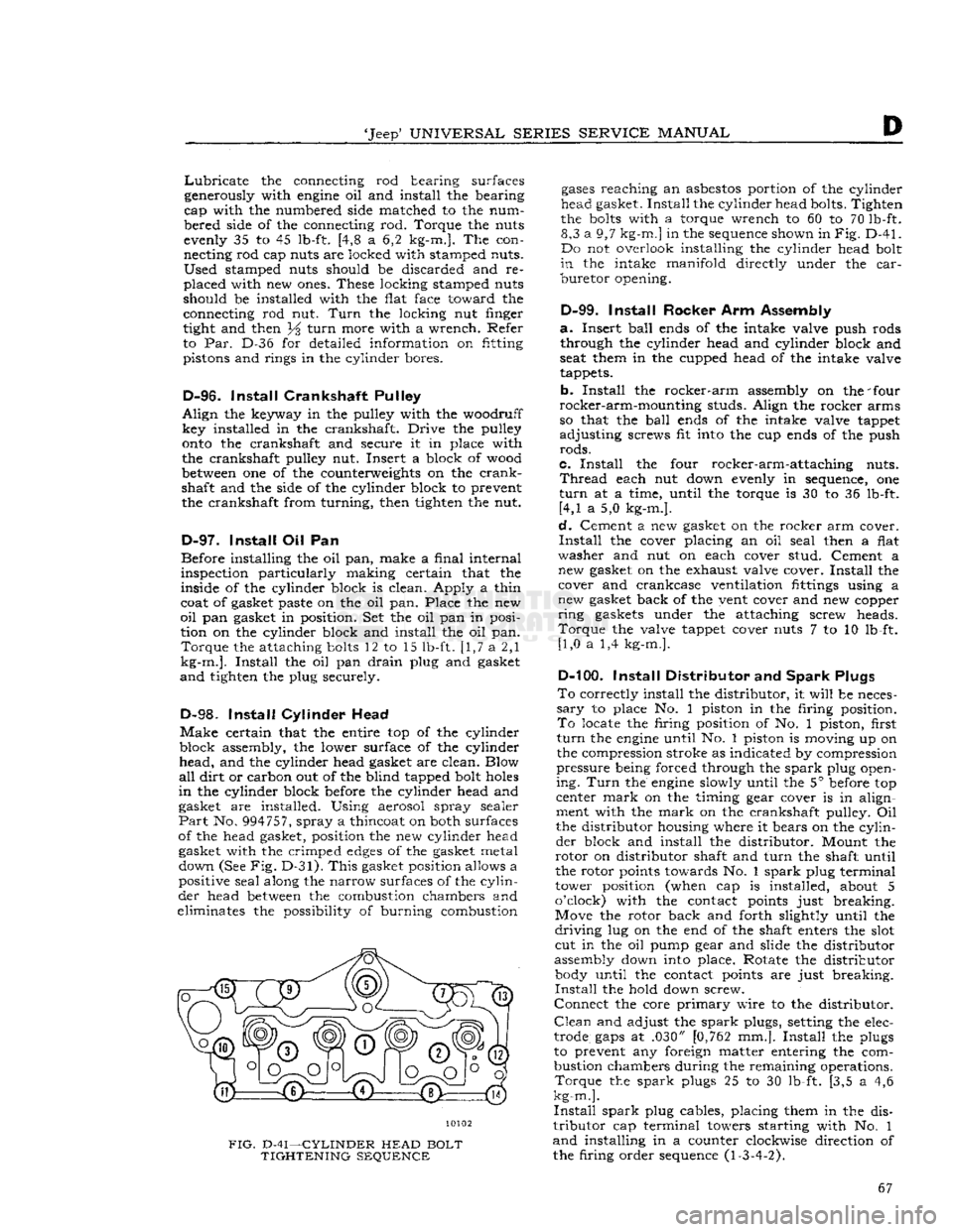
10102
FIG.
D-41—CYLINDER
HEAD
BOLT
TIGHTENING
SEQUENCE
gases
reaching
an
asbestos
portion of the cylinder
head gasket.
Install
the cylinder head bolts. Tighten
the
bolts
with a torque wrench to 60 to 70 lb-ft. 8,3 a 9,7
kg-m.]
in the sequence shown in
Fig.
D-41.
Do not overlook installing the cylinder head bolt
in
the intake
manifold
directly under the
car
buretor
opening.
D-99.
Install
Rocker Arm Assembly
a.
Insert
ball
ends of the intake valve push rods through the cylinder head and cylinder block and
seat them in the cupped head of the intake valve
tappets.
b.
Install
the
rocker-arm
assembly on the 'four
rocker-arm-mounting
studs. Align the rocker arms
so that the
ball
ends of the intake valve tappet
adjusting
screws fit into the cup ends of the push
rods.
c.
Install
the four rocker-arm-attaching nuts.
Thread
each nut down evenly in sequence, one
turn
at a time, until the torque is 30 to 36 lb-ft. [4,1 a 5,0 kg-m.].
d.
Cement a new gasket on the rocker arm cover.
Install
the cover placing an oil seal then a flat
washer
and nut on each cover stud. Cement a new gasket on the exhaust valve cover.
Install
the cover and crankcase ventilation fittings using a
new gasket back of the vent cover and new copper
ring
gaskets under the attaching screw heads.
Torque
the valve tappet cover nuts 7 to 10 lb-ft. [1,0 a 1,4 kg-m.].
D-100.
Install
Distributor and
Spark
Plugs
To
correctly install the distributor, it
will
be neces
sary
to place No. 1 piston in the firing position.
To
locate the firing position of No. 1 piston, first
turn
the
engine
until No. 1 piston is moving up on
the compression stroke as indicated by compression
pressure
being forced through the
spark
plug open
ing.
Turn
the
engine
slowly until the 5° before top
center
mark
on the timing gear cover is in align
ment with the
mark
on the crankshaft pulley. Oil
the distributor housing where it bears on the
cylin
der
block and install the distributor. Mount the
rotor
on distributor shaft and
turn
the shaft until
the rotor points towards No. 1
spark
plug terminal
tower position (when cap is installed, about 5
o'clock) with the contact points just breaking.
Move the rotor back and forth slightly until the
driving
lug on the end of the shaft enters the slot cut in the oil pump gear and slide the distributor
assembly down into place. Rotate the distributor body until the contact points are just breaking.
Install
the hold down screw.
Connect
the core
primary
wire to the distributor.
Clean
and adjust the
spark
plugs, setting the elec
trode
gaps
at .030" [0,762 mm.].
Install
the plugs
to prevent any foreign matter entering the com
bustion chambers during the remaining operations.
Torque
the
spark
plugs 25 to 30 lb-ft. [3,5 a 4,6
kg-m.].
Install
spark
plug cables, placing them in the dis
tributor
cap terminal towers starting with No. 1
and
installing in a counter clockwise direction of
the firing order sequence (1-3-4-2). 67
Page 69 of 376
'Jeep9
UNIVERSAL
SERIES
SERVICE
MANUAL
h.
Check
ignition (distributor) timing; reset if
necessary.
i.
Check
carburetor
adjustments; reset if necessary,
j.
With
engine
fully warmed up, tighten cylinder
head and manifold
bolts
and nuts to specified
torque.
Check
cylinder head gaskets and
bolts
for
air
or coolant leaks.
Note:
Tightness of cylinder head
bolts
should be
checked and corrected after 500 to 600 miles [800
a
960 km.] of normal operation.
k.
Check
fan belt tension; adjust if necessary.
I.
Check
for and correct any oil leak, fuel leak or
coolant leak.
D-107.
VALVE
ADJUSTMENT
Proper
valve adjustment is important to prevent
burning
of valves and poor
engine
performance.
This
adjustment consists of obtaining a specified
lash
in the valve mechanism. The exhaust valve
tappets and the intake valve rocker arms should be adjusted to the proper clearance with the
engine
cold (at room temperature). Valve clearance can
be properly adjusted only when the tappet is on the
heel or low portion of the cam.
INTAKE
OPENS
9°
BTC?
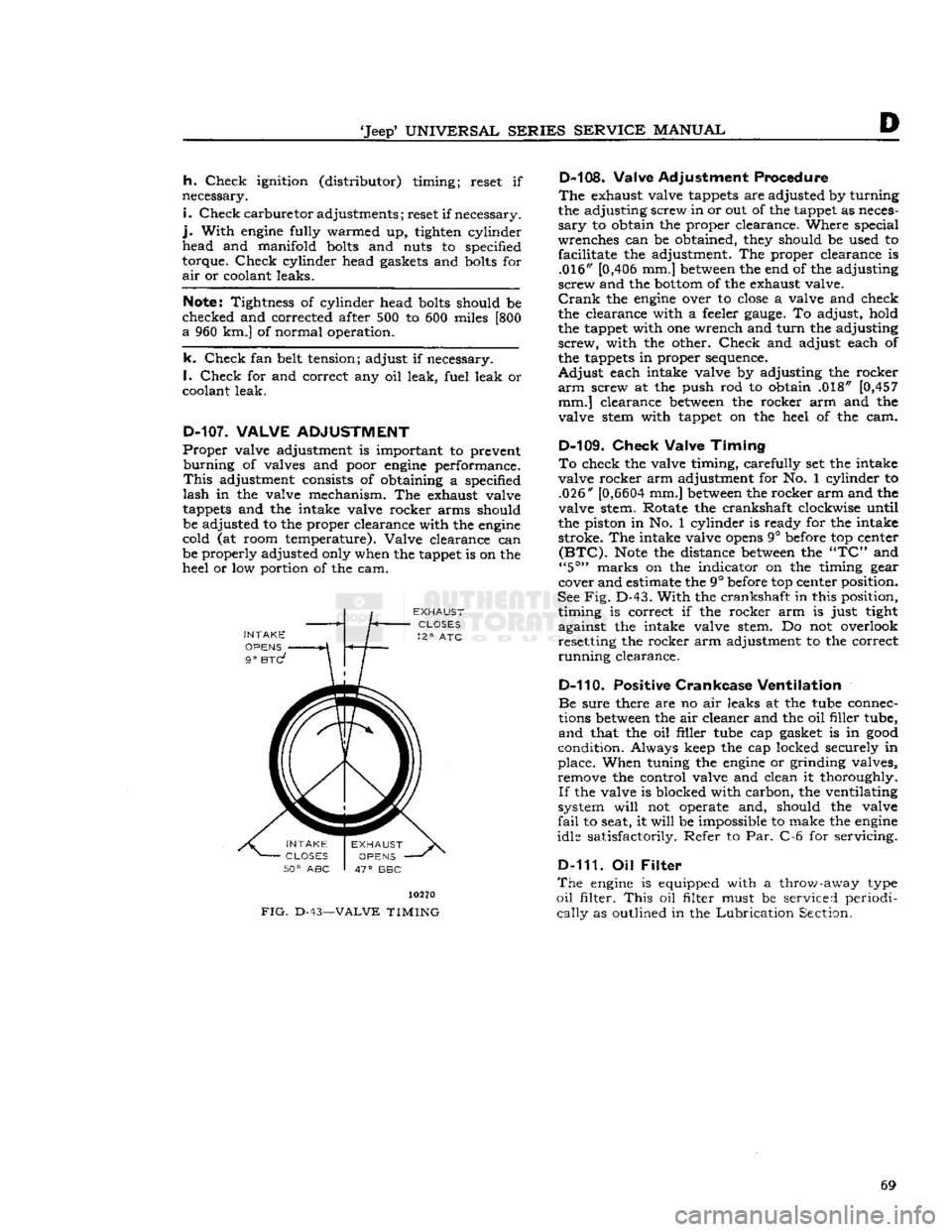
FIG.
D-43-
10270
-VALVE
TIMING
D-108. Valve Adjustment Procedure
The
exhaust valve tappets are adjusted by turning
the adjusting screw in or out of the tappet as neces
sary
to obtain the proper clearance. Where special
wrenches can be obtained, they should be used to facilitate the adjustment. The proper clearance is .016" [0,406 mm.]
between
the end of the adjusting
screw and the
bottom
of the exhaust valve.
Crank
the
engine
over to
close
a valve and check
the clearance with a feeler
gauge.
To adjust, hold
the tappet with one wrench and
turn
the adjusting
screw,
with the other.
Check
and adjust each of
the tappets in proper sequence.
Adjust
each intake valve by adjusting the rocker
arm
screw at the push rod to obtain .018" [0,457 mm.] clearance
between
the rocker arm and the
valve stem with tappet on the heel of the cam.
D-109.
Check
Valve
Timing
To
check the valve timing, carefully set the intake
valve rocker arm adjustment for No. 1 cylinder to .026"
[0,6604
mm.]
between
the rocker arm and the
valve stem. Rotate the crankshaft clockwise until
the piston in No. 1 cylinder is ready for the intake stroke. The intake valve
opens
9° before top center
(BTC).
Note
the distance
between
the
"TC"
and
"5°"
marks on the indicator on the timing gear
cover and estimate the 9° before top center position.
See
Fig.
D-43.
With
the crankshaft in this position, timing is correct if the rocker arm is just tight
against the intake valve stem. Do not overlook resetting the rocker arm adjustment to the correct
running
clearance.
D-110. Positive
Crankcase
Ventilation
Be
sure there are no air leaks at the tube connec
tions
between
the air cleaner and the oil filler tube,
and
that the oil filler tube cap gasket is in
good
condition. Always keep the cap locked securely in
place. When tuning the
engine
or grinding valves, remove the control valve and clean it thoroughly.
If
the valve is blocked with carbon, the ventilating
system
will
not operate and, should the valve
fail
to seat, it
will
be impossible to make the
engine
idle satisfactorily. Refer to Par. C-6 for servicing.
D-111. Oil
Filter
The
engine
is equipped with a throw-away type
oil
filter.
This
oil filter must be serviced periodi
cally
as outlined in the
Lubrication
Section. 69
Page 115 of 376
'Jeep*
UNIVERSAL
SERIES
SERVICE
MANUAL
E
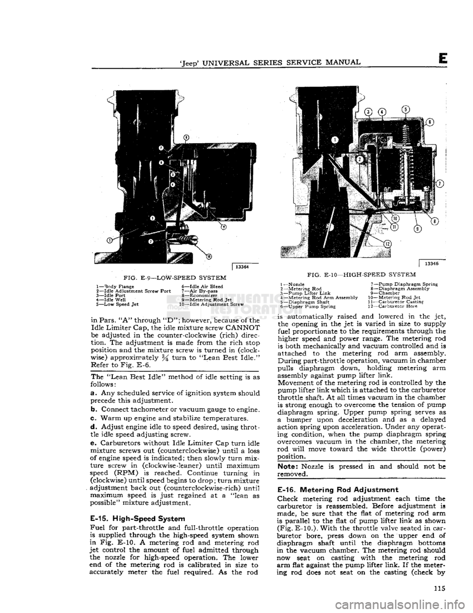
FIG.
E-9—LOW-SPEED
SYSTEM
1—
Body
Flange 6—Idle Air Bleed
2—
-Idle
Adjustment Screw Port
7—Air
By-pass
3—
Idle
Port 8—Economizer
4—
Idle
Well
9—Metering Rod Jet
5—
Low
Speed Jet 10—Idle Adjustment Screw
in
Pars.
"A"
through
"D";
however, because of the
Idle
Limiter
Cap,
the idle mixture screw
CANNOT
be adjusted in the counter-clockwise
(rich)
direc
tion. The adjustment is made from the
rich
stop
position and the mixture screw is turned in (clock
wise) approximately %
turn
to
"Lean
Best
Idle."
Refer
to Fig. E-6.
The
"Lean
Best
Idle"
method of idle
setting
is as
follows:
a.
Any scheduled service of ignition system should precede this adjustment.
b.
Connect tachometer or vacuum
gauge
to
engine.
c.
Warm
up
engine
and stabilize temperatures.
d.
Adjust
engine
idle to
speed
desired, using throttle idle
speed
adjusting screw.
e. Carburetors without Idle
Limiter
Cap
turn
idle
mixture
screws out (counterclockwise) until a
loss
of
engine
speed
is indicated; then slowly
turn
mix
ture
screw in (clockwise
-leaner)
until maximum
speed
(RPM) is reached. Continue turning in (clockwise) until
speed
begins
to drop;
turn
mixture
adjustment back out (counterclockwise
-rich)
until
maximum
speed
is just regained at a "lean as
possible" mixture adjustment.
E-15.
High-Speed System
Fuel
for part-throttle and full-throttle operation
is supplied through the high-speed system shown
in
Fig. E-10. A metering rod and metering rod
jet
control the amount of fuel admitted through the nozzle for high-speed operation. The lower
end of the metering rod is calibrated in size to
accurately
meter the fuel required. As the rod
|
13346
FIG.
E-10—HIGH-SPEED
SYSTEM
1—Nozzle 7—Pump Diaphragm
Spring
2
—Metering
Rod 8—Diaphragm Assembly
3—
Pump
Lifter
Link
9—Chamber
4—
Metering
Rod Arm Assembly
10—Metering
Rod Jet 5—
Diaphragm
Shaft
11—Carburetor
Casting
6—
Upper
Pump Spring 12—Carburetor Bore is automatically raised and lowered in the jet,
the opening in the jet is varied in size to supply
fuel
proportionate to the requirements through the
higher
speed
and power range. The metering rod
is both mechanically and vacuum controlled and is
attached to the metering rod arm assembly.
During
part-throttle operation, vacuum in chamber
pulls
diaphragm down, holding metering arm
assembly against pump lifter
link.
Movement of the metering rod is controlled by the
pump lifter
link
which is attached to the carburetor
throttle shaft. At all
times
vacuum in the chamber
is strong
enough
to overcome the tension of pump
diaphragm
spring. Upper pump spring serves as
a
bumper upon deceleration and as a delayed
action spring upon acceleration. Under any operat ing condition, when the pump diaphragm spring
overcomes vacuum in the chamber, the metering
rod
will
move
toward the wide throttle (power) position.
Note:
Nozzle is pressed in and should not be
removed.
E-16.
Metering Rod Adjustment
Check
metering rod adjustment each time the
carburetor
is reassembled. Before adjustment is
made, be sure that the flat of metering rod arm
is parallel to the flat of pump lifter
link
as shown
(Fig.
E-10.).
With
the throttle valve
seated
in
car
buretor
bore, press down on the upper end of
diaphragm
shaft until the diaphragm
bottoms
in
the vacuum chamber. The metering rod should
now
seat
on casting with the metering rod
arm
flat against the pump lifter
link.
If the meter
ing rod
does
not
seat
on the casting (check by 115
Page 144 of 376
Fl
EXHAUST EMISSION CONTROL SYSTEMS
12793
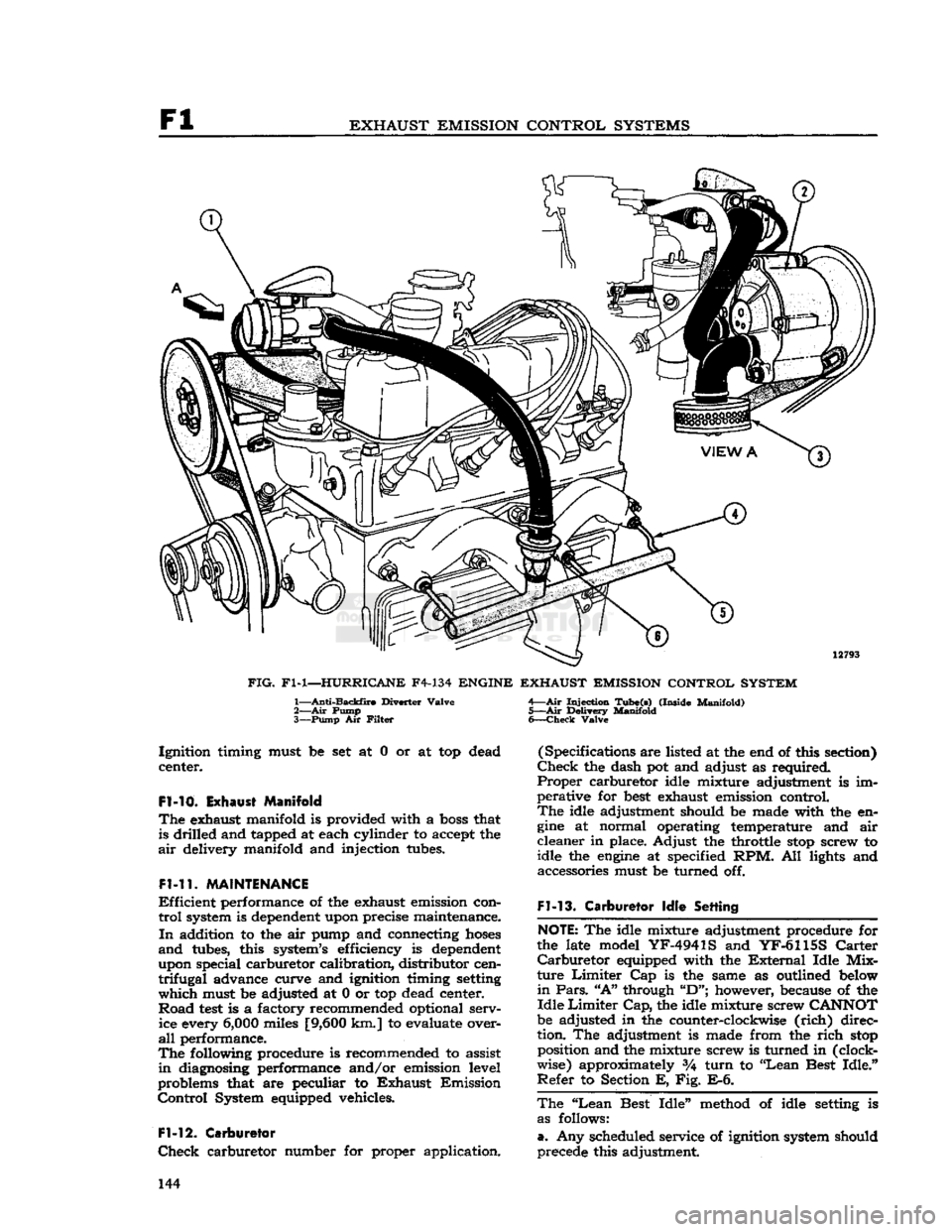
FIG.
Fl-1—HURRICANE
F4-134
ENGINE EXHAUST EMISSION CONTROL SYSTEM
1—
Anti-Backfire
Diverter
Valve
2— Air
Pump
3—
Pump
Air
Filter
Injection
Tube(s)
(Inside
Manifold)
5—Air
Delivery
Manifold
6—
Check
Valve
Ignition
timing must be set at 0 or at top dead
center.
Fl-10.
Exhaust Manifold
The
exhaust manifold is provided with a
boss
that is drilled and tapped at each cylinder to accept the
air
delivery manifold and injection tubes.
Fl-11.
MAINTENANCE
Efficient
performance of the exhaust emission con
trol
system is dependent upon precise maintenance.
In
addition to the air pump and connecting
hoses
and
tubes, this system's efficiency is dependent
upon special carburetor calibration, distributor cen
trifugal
advance curve and ignition timing setting
which
must be adjusted at 0 or top dead center.
Road
test
is a factory recommended optional serv ice every
6,000
miles
[9,600
km.] to evaluate over
all
performance.
The
following procedure is recommended to assist
in
diagnosing performance and/or emission level
problems that are peculiar to
Exhaust
Emission
Control
System equipped vehicles.
Fl-12.
Carburetor
Check
carburetor number for proper application. (Specifications are listed at the end of this section)
Check
the dash pot and adjust as required.
Proper
carburetor idle mixture adjustment is im
perative for
best
exhaust emission control.
The
idle adjustment should be made with the en
gine
at normal operating temperature and air
cleaner
in place. Adjust the throttle
stop
screw to
idle the
engine
at specified RPM. All lights and accessories must be turned off.
Fl-13.
Carburetor
Idle
Setting
NOTE:
The idle mixture adjustment procedure for
the late model
YF-4941S
and
YF-6115S
Carter
Carburetor
equipped with the
External
Idle
Mix
ture
Limiter
Cap is the same as outlined below
in
Pars.
"A"
through
"D";
however, because of the
Idle
Limiter
Cap,
the idle mixture screw
CANNOT
be adjusted in the counter-clockwise
(rich)
direc
tion. The adjustment is made from the
rich
stop
position and the mixture screw is turned in (clock
wise) approximately %
turn
to "Lean Best
Idle."
Refer
to Section E, Fig. E-6.
The
"Lean
Best
Idle"
method of idle setting is as follows:
a.
Any scheduled service of ignition system should
precede this adjustment. 144
Page 145 of 376
'Jeep'
UNIVERSAL
SERIES SERVICE
MANUAL
Fl
b. Connect tachometer to
engine.
c.
Warm
up
engine
and stabilize temperatures.
d.
Adjust
engine
idle to
speed
desired, using throt
tle idle
speed
adjusting screw.
e.
Carburetors without Idle
Limiter
Cap turn idle mixture screws out (counterclockwise) until a
loss
of
engine
speed
is indicated; then, slowly turn mix
ture screw in (clockwise-leaner) until maximum
speed
(RPM) is reached. Continue turning in (clockwise) until
speed
begins
to drop; turn mixture
adjustment back out (counterclockwise-richer) un
til
maximum
speed
is just regained at a "lean as
possible" mixture adjustment.
Fl-14.
Distributor
Check
the distributor number for proper appli
cation.
Check
the distributor cam dwell angle and
point condition and adjust to specifications or re place as required. (Specifications listed at the end
of this section)
Check
ignition timing and set at
0°
or
TDC.
Fl-15.
Anti-iackfire
Diverter Valve
The
anti-backfire valve remains closed
except
when
the throttle is closed rapidly from an
open
position.
To
check the valve for proper operation, accelerate
the
engine
in neutral, allowing the throttle to
close
rapidly.
The valve is operating satisfactorily when
no exhaust system backfire occurs. A further check
to determine whether the valve is functioning can be made by removing from the anti-backfire valve
the large
hose
Which
connects to the check valve.
Accelerate the
engine
to allow the throttle to
close
rapidly.
The valve is operating satisfactorily if a
momentary interruption of rushing air is audible.
Fl-16.
Check Valve
The
check valve prevents the reverse flow of ex
haust
gases
to the pump in the
event
the pump
should, for any reason,
become
inoperative or should exhaust pressure ever
exceed
pump pressure.
To
check this valve for proper operation, remove the air supply
hose
from the pump at the
distri
bution manifold.
With
the
engine
running, listen for exhaust leakage at the check valve which is
connected to the distribution manifold.
Fl-17.
Air
Pump
Check
for proper drive belt tension with belt tension
gauge
W-283. The belt strand tension should be
50-60
pounds on a belt with previous service, meas
ured
on the
longest
accessible span
between
two pulleys. When installing a new belt, adjust the
tension to
60-80
pounds tension. DO NOT PRY
ON
THE DIE
CAST
PUMP
HOUSING.
To
check the pump for proper operation, remove the air
outlet
hose
at the pump.
With
the
engine
running,
air discharge should be
felt
at the pump
outlet
opening. The pump
outlet
air pressure, as determined by the relief valve, is preset and is not
adjustable.
The
air pump
rear
cover assembly, housing the pressed in inlet and discharge tubes, and the pres
sure relief valve are the only pump
components
recommended for service replacement. These parts
are
to be replaced only when damaged as a result
of handling or in the
event
the relief valve was
tampered with.
Fl-18.
Carburetor
Air
Cleaner
Every
6000
miles
[9,600
km.] clean the inside
sur
face at the sump and
refill
to indicated oil level with
SAE
40 or 50
engine
oil
above
32 F; SAE 20
below
32 F. Wash filter
element
in kerosene and
drain.
Reassemble the air cleaner.
More
frequent cleaning and replacement is advis able when the car is operated in dusty areas or on
unpaved roads. Accumulated dirt restricts air flow,
reducing fuel
economy
and performance.
Fl-19.
REMOVAL
PROCEDURES
The
following paragraphs
give
the procedures for removing the major units of the Exhaust Emission
Control
System and the required equipment
needed.
Fl-20.
Air
Pump
Loosen
the air pump adjusting strap to facilitate
drive
belt removal. Remove the air pump air dis
charge hose(s) and air filter attachment. Separate
the air pump from its mounting bracket. At time of installation, torque tighten the air pump mounting
bolts
to
30-40
lbs-ft. [4,15 a 5,53 kg-m.]. Adjust
the belt strand tension to
50-60
pounds on a belt
with previous service and
60-80
pounds on a new
belt.
Fl-21.
Anti-Backfire
Diverter Valve
The
anti-backfire diverter valve removal requires disconnecting the
hoses
and bracket to
engine
at
taching screws.
Fl-22.
Air
Distribution
Manifold
and
Injection Tubes
In
order to remove the air distribution manifold
without bending the tubing, which could result in
fractures
or leakage, it is necessary to remove the
exhaust manifold as an assembly from the
engine.
After
the exhaust manifold assembly is removed
from
the
engine,
place the manifold in a vise and
loosen
the air distribution manifold
tube
retaining nuts at each cylinder exhaust port. Tap the injec
tion
tubes
lightly to allow the air distribution mani
fold to be pulled away partially from the exhaust manifold. The stainless steel injection
tubes
in the
exhaust manifold may have
become
partially fused
to the air distribution manifold and, therefore, may
require
application of heat to the joint in order to
separate. While applying heat to the joint, rotate
the injection
tubes
with pliers being careful not to
damage the
tubes
by applying excessive force.
At
time of installation, the air injection
tubes
must
be positioned into the exhaust manifold prior to
placing the exhaust manifold assembly on the en gine.
Note:
Two different length injection
tubes
are used.
The
shorter length injection
tubes
must be inserted into cylinders 1 and 4. 145
Page 156 of 376
F2
EXHAUST EMISSION CONTROL SYSTEMS
the throttle
stop
screw to idle the
engine
at 650
to 700 rpm.
F2-17. Carburetor Idle Setting
The
"Lean
Best
Idle"
Method of Idle Setting is as
follows:
a.
Any scheduled service of ignition system should
precede this adjustment
b.
Connect tachometer to engine.
c.
Warm
up
engine
and stabilize temperatures.
d.
Adjust
engine
idle to speed desired, using throt
tle idle speed adjusting screw.
e.
Turn
idle mixture screws out (counterclockwise)
until
a
loss
of
engine
speed is indicated; then slowly
turn
mixture screws in (clockwise-leaner)
until
maximum speed (rpm) is reached. Continue
turning
in (clockwise) until speed begins to drop;
turn
mixture adjustment back out (counterclock
wise-richer)
until maximum speed is just regained
at
a "lean as possible" mixture adjustment.
F2-18. Distributor
The
ignition distributor used with the
Exhaust
Emission
Control
System is the same as that used
on
engines
without
Exhaust
Emission
Control.
Check
the distributor cam dwell angle and point
condition.
Check
ignition timing and adjust to specifications shown on the last
page
of this section.
F2-19.
Anti-Backfire
Valve
The
anti-backfire valve remains closed except when
the throttle is closed rapidly from an open position.
To
check the valve for proper operation, accelerate
the
engine
in neutral, allowing the throttle to close
rapidly.
The valve is operating satisfactorily when
no exhaust system backfire occurs. A further check
to determine whether the valve is functioning can
be made by removing from the anti-backfire valve
the large
hose
which connects the valve to the
pump.
With
a finger placed over the open end of
the
hose
(not the valve), accelerate the
engine
and allow the throttle to close rapidly. The valve is
operating satisfactorily if a momentary air rushing
noise is audible.
F2-20.
Check
Valve
The
check valves in the lines to the air distribution manifolds prevent the reverse flow of exhaust
gases
to the pump in the event the pump should, for
any
reason,
become
inoperative or should exhaust
pressure
ever exceed pump pressure.
To
check this valve for proper operation, remove the air supply
hose
from the pump at the check
valve.
With
the
engine
running, listen for exhaust
leakage at the check valve which is connected to
the distribution manifold.
F2-21.
Air
Pump
Check
for proper drive belt tension with belt tension
gauge
W-283. The belt strand tension should be 60 pounds measured on the
longest
accessible span
between two pulleys. DO NOT PRY ON THE
DIE
CAST
PUMP
HOUSING. To
check the pump for proper operation, remove
the air
outlet
hose
at the pump.
With
the
engine
running,
air discharge should be felt at one of
the pump
outlet
openings. The pump
outlet
air
pressure,
as determined by the relief valve, is preset
and
is not adjustable.
The
air pump
rear
cover assembly, housing the pressed in inlet and discharge tubes, and the pres
sure
relief valve are the only pump components
recommended for service replacement. These parts
are
to be replaced only when damaged as a result
of handling or in the event the relief valve was
tampered with.
F2-22.
Intake Manifold
Intake
manifold leaks must not be overlooked. Air
leakage at the intake manifold may be compen
sated for by
richer
idle mixture setting, however, this
will
usually cause uneven fuel-air distribution
and
will
always result in
loss
of performance and
exhaust emission control. To check for air leakage
into the intake manifold, apply kerosene or naph
tha,
on the intake manifold to cylinder head joints
and
observe whether any changes in
engine
rpm
occur.
If an air leak is indicated, check the mani
fold to cylinder head bolt torque. The correct torque is 25-35 lbs. ft. [3,46 a 4,84 kg-m.]. If the
leak
is
still
evident,
loosen
the manifold assembly
and
torque-tighten the bolts evenly.
Start
from the center and use proper torque values. Replace the
manifold
gasket if the leak
still
exists.
Clean
both
mating surfaces and check for
burrs
or other ir
regularities.
Always
torque the bolts evenly to the specified
torque value to prevent warpage.
F2-23.
Carburetor
Air
Cleaner
—Oil
Bath
Every
6,000
miles [9,600 km.] disconnect attach
ing
hoses
and unscrew the wing nut from the top
of the air cleaner and lift it off the carburetor.
Lift
the cover and filter element off the oil sump.
Clean
the inside surface of the sump and
refill
to
indicated
oil level with SAE 40 or 50
engine
oil
above 32 F; SAE 20 below 32 F.
Wash
filter element in kerosene and
drain.
Reassemble the air
cleaner
and install on carburetor.
More
frequent cleaning and replacement are advis able when the car is operated in dusty areas or on
unpaved
roads. Accumulated
dirt
restricts air flow,
reducing
fuel economy and performance.
F2-24.
REMOVAL PROCEDURES
The
following paragraphs
give
the procedures for removing the major units of the exhaust emission
control
system and the required equipment needed.
F2-2S.
Air
Pump
Loosen
the air pump mounting bracket bolts. Re move the air pump air hose(s). Separate the air pump from its mounting bracket. At time of install
ation,
torque tighten the air pump mounting bolts
to
30-40
lbs.-ft [4,15 a 5,53 kg-m.].
Adjust
the
belt strand tension to 60 pounds. 156
Page 164 of 376
G
COOLING SYSTEM
engine
connections. Insert flushing gun and flush
heater core.
Care
must be taken when applying air
pressure to prevent damage to the heater core.
G-2.
Filling
Cooling System
To
fill
the cooling system, remove the
fill
cap and
fill
the tank to the top. Replace the cap and run
the
engine
at medium speed for approximately one
minute. Remove the cap and recheck the coolant level. Add more coolant if necessary to bring the level back to the top of the tank. If the cooling system is filled when the
engine
is cold, recheck the coolant level after the
engine
has warmed up.
This
will
ensure that the thermostat has opened allow ing complete cooling system circulation.
Always
correct any cooling system leaks before installing antifreeze. A corrosion inhibitor should be used in the cooling system to prevent the forma
tion of rust and scale. A quality brand antifreeze containing a corrosion inhibitor should be used.
When
the antifreeze is drained in the spring, a
corrosion inhibitor should be added with the water.
Note:
Cooling system components for both V6 and
F4
engines
are shown in
Figs.
G-2 and G-3.
G-3. Draining
Cooling System
To
completely
drain
the cooling system, open the
drain
in the
bottom
of the radiator and also a
drain
on the right side of the cylinder block on the
Hurricane
F4 engine. The Dauntless V-6
engine
has two
drain
plugs, one located on each side of the cylinder block. Both plugs must be removed to
completely
drain
the cooling system.
Remove the radiator cap to break any vacuum
that may have developed.
Should
the cooling solution be lost from the system
and
the
engine
become
overheated do not
refill
the system immediately but allow the
engine
to cool or
refill
slowly while the
engine
is running. If
cold solution is poured into the radiator while the
engine
is overheated there is danger of cracking the
cylinder
block and/or cylinder head.
G-4.
Radiator Pressure
Cap
All
radiators are equipped with pressure caps which
reduce evaporation of cooling solution and make the
engines
more efficient by permitting slightly
higher operating temperatures. When operating
properly,
the pressure cap permits pressure build-up
in
the cooling system during periods of severe heat
load.
This
pressure increases the boiling point of the coolant and thus reduces overflow losses. The
effectiveness
of the cap is limited by its opening
pressure and the boiling point of the coolant (see
note
below). The pressure cap employs a spring-
loaded, rubber-faced pressure seal which presses against a seat in the radiator top tank. Spring pres
sure
determines the opening pressure of the valve.
A
typical pressure cap is shown in Fig. G-5.
Note:
Refer to cooling system specifications (Par.
G-21)
for opening (relief) pressure when the ve
hicle is equipped with either the
Hurricane
F4
or
Dauntless V-6 engine. If a new cap is required, always install a cap of the same type and pressure
rating
specified. It should never be altered or re
placed by a plain cap.
A
vacuum release valve (Fig. G-5) is employed to
prevent undesirable vacuum build-up when the system
cools
down. The vacuum release valve is
held against its seat under light spring pressure.
Vacuum
in the system is relieved by the valve
which
opens
at V2 to 1 psi. [0,035 a 0,07 kg-cm2]
vacuum.
A pressure tester can be used to check and
test
the vacuum pressure rate (see Fig. G-6).
Although the mechanism of the pressure cap re quires no maintenance, the cap should be inspected
periodically for cleanliness and freedom of opera tion. The pressure cap gasket and radiator filler neck seat should also be inspected to be sure they
are
providing a proper seal. If the rubber face of
the valve is defective, a new cap should be installed.
Filler
neck reseating
tools
are commercially
avail
able to correct minor
defects
at the surface of the seat. Follow instructions of the reseating tool manu
facturer.
To
remove the radiator pressure cap when the
engine
coolant temperature is high or boiling, place
a
cloth over the pressure cap and
turn
counter clockwise about Vi
turn
until the first (pressure release)
stop
is reached. Keep the cap in this posi
tion until all pressure is released.
Then
push cap
down and
turn
still
further until cap can be re moved. To install the pressure cap, place it in posi
tion and
turn
it clockwise as far as it
will
go.
Caution:
Use extreme care in removing the radiator
pressure cap. In overheated systems, the sudden release of pressure can cause a steam flash and this
flash,
or the
loosened
cap can cause serious personal
injury.
G-5.
RADIATOR
Maintenance of the radiator consists of keeping
the exterior of the radiator core clean, the interior free from rust and scale, and the radiator free from
leaks.
Check
the cooling system fluid level and for
leaks each
2000
miles
[3.200
km.] or every 30
days, whichever occurs first.
This
exterior of the
radiator
core should be cleaned and the radiator inspected for leaks each
6000
miles
[9.600
km.]
of normal service of the vehicle. Cleaning should be performed by blowing out with air stream or water stream directed from the
rear
of the radiator.
Visual
inspection is not sufficient as the accumula tion of small particles of foreign material on core
surfaces can restrict cooling without closing the core openings.
Radiator
leakage occasionally results from cor
rosion perforation of the metal but most leakage results from mechanical failure of soldered joints
when too much strain has been put on the joint.
Fractures
occur most
often
at the joint where the
radiator
inlet and
outlet
pipes are attached to the
tanks.
When the seams break, the entire soldered
joint
is
exposed
and can corrode, but breakage
rather
than corrosion is the
primary
cause of seam
leakage. Examine the radiator carefully for leaks before and after cleaning. Cleaning may uncover points of leakage already existing but plugged with
rust.
White, rusty, or colored leakage stains indicate 164
Page 184 of 376
H
ELECTRICAL
SYSTEM
14237
FIG.
H-l2—DRILLING DISTRIBUTOR
CAP 1—%'
Vent
Hole
Location
Seal
the distributor cap access window and the
area
beneath the distributor cap with caulking
compound as shown in
Fig. H-ll.
At approximately
180°
from the distributor cap access window,
drill
a
[2,38 mm.] vent
hole
[31,75
mm.]
from the
bottom
of the distributor cap as shown
in
Fig. H-l2. b. To adjust breaker point cam dwell, refer to
Par.
C-10.
H-25.
Centrifugal Advance
Refer
to Fig. H-13.
Inspect for
excessive
wear
between
centrifugal
weights
and advance cam, or pivot pins.
Turn
weight
base plate in a clockwise direction until
weights
are fully extended, then release and allow springs to return to retard position. Repeat several times. Springs should return
weights
to
stop
without sticking and there should be no
excess
free
movement
in the retard position.
H-26.
Distributor Removal
a.
Disconnect the distributor primary wire from
coil
and disconnect
hose
from vacuum advance
mechanism of distributor. Insert a screwdriver in upper
slotted
end of two distributor cap retainers.
Press
downward, and turn 90
degrees
counterclock
wise to release. Remove cap from distributor hous ing.
b. Make an index
mark
on distributor housing
(Fig.
H-14) in line with center of rotor. Carefully
note
the direction the vacuum unit
points
in
rela
tion to
engine
so that the distributor can be in
stalled in the same position after it is serviced.
Caution:
If
engine
is turned over while distributor is removed,
complete
ignition timing procedure
must be followed upon distributor installation.
c. Remove attaching cap screw and distributor
clamp from timing chain cover.
Lift
distributor up
ward
and remove it from timing chain cover.
H-27.
Distributor Disassembly (Delco)
Refer
to Fig. H-l5.
a.
Remove rotor, breaker point assembly, and capacitor from distributor.
FIG.
H-13—CENTRIFUGAL ADVANCE
MECHANISM (DELCO)
A—No
Advance
1—
Advance
Weights
2—
Advance
Cam
B—Full
Advance
3—Full
Advance
FIG.
H-14—DELCO DISTRIBUTOR
ROTOR
POSITION
1
—Rotor
Tip
Lined
Up
With
Notch
184
Page 186 of 376
ELECTRICALJ
SYSTEM
d.
Inspect for
excessive
wear
between
centrifugal
weights
and advance cam and pivot pins.
Turn
weight
base plate in a clockwise direction until
weights
are fully extended. Release and allow
springs to return
weights
to
retard
position. Repeat several times. Springs should return
weights
to
stop
without sticking and there should be no
excessive
free
movement
in the
retard
position. Inspect
springs for distortion and fatigue.
e. Inspect cam
lobes
for scoring or
excessive
wear.
Check
weight
base plate for binding or
excessive
looseness
on distributor shaft.
f.
Check
breaker plate for
excessive
looseness
on
outside
diameter of upper distributor shaft bushing.
Check
breaker plate ground lead for poor
spot
we
Id
at plate end and for
loose
or frayed terminal con
nections.
g.
Check
for
excessive
wear
between
distributor
shaft and bushings in housing. Inspect shaft for distortion. Inspect gear for scoring of
teeth
or
excessive
wear.
h.
Inspect rod end of vacuum advance mechanism
for
excessive
wear. Push rod
into
unit as far as
possible, hold finger tightly over nipple, then re
lease
rod. After about 15 seconds, remove finger
from nipple, and
notice
if air is drawn
into
unit.
If
not, diaphragm is leaking and unit must be
replaced.
H-29.
Distributor Reassembly
Refer
to Fig. H-l5.
a.
Install
distributor
primary
lead and rubber grommet in distributor housing. Mount vacuum
advance unit on housing with two
slotted
attaching
screws; insert ground lead terminal of breaker plate under outer mounting screw.
b.
Install
felt
washer over upper shaft bushing of
distributor housing and apply a few drops of light
oil.
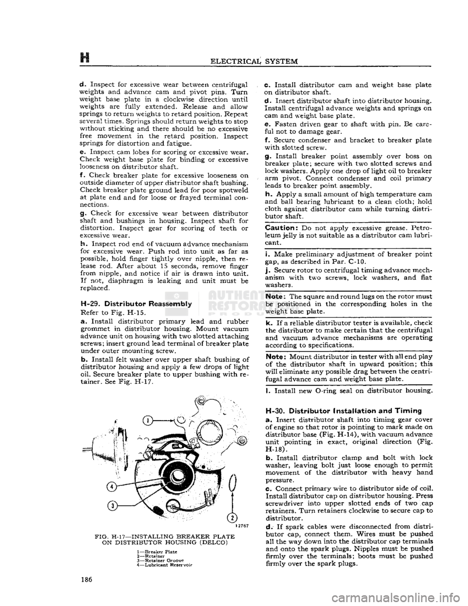
Secure breaker plate to upper bushing with re tainer. See Fig. H-17.
12767
FIG.
H-17—INSTALLING
BREAKER
PLATE
ON
DISTRIBUTOR
HOUSING
(DELCO)
1—
Breaker
Plate
2—
Retainer
3—
Retainer
Groove
4—
Lubricant
Reservoir c.
Install
distributor cam and
weight
base plate
on distributor shaft.
d.
Insert distributor shaft
into
distributor housing.
Install
centrifugal advance
weights
and springs on
cam
and
weight
base plate. e. Fasten driven gear to shaft with pin. Be care
ful
not to damage gear.
f.
Secure condenser and bracket to breaker plate
with
slotted
screw.
g.
Install
breaker point assembly over
boss
on
breaker
plate; secure with two
slotted
screws and
lock washers. Apply one drop of light oil to breaker
arm
pivot. Connect condenser and coil
primary
leads to breaker point assembly.
h.
Apply a small amount of high temperature cam
and
ball
bearing lubricant to a clean cloth; hold cloth against distributor cam while turning
distri
butor shaft.
Caution:
Do not apply
excessive
grease. Petro
leum jelly is not suitable as a distributor cam
lubri
cant.
i.
Make preliminary adjustment of breaker point
gap, as described in Par. C-10.
].
Secure rotor to centrifugal timing advance mech
anism with two screws, lock washers, and flat
washers.
Note:
The square and round
lugs
on the rotor must
be positioned in the corresponding
holes
in the
weight
base plate.
k. If a reliable distributor tester is available, check
the distributor to make certain that the centrifugal
and
vacuum advance mechanisms are operating
according to specifications.
Note:
Mount distributor in tester with all end play
of the distributor shaft in upward position; this
will
eliminate any possible drag
between
the centri fugal advance cam and
weight
base plate.
I.
Install
new
O-ring
seal on distributor housing.
H-30.
Distributor
Installation
and
Timing
a.
Insert distributor shaft
into
timing gear cover
of
engine
so that rotor is pointing to
mark
made on distributor base (Fig. H-14), with vacuum advance
unit pointing in exact, original direction (Fig.
H-18).
b.
Install
distributor clamp and
bolt
with lock
washer, leaving
bolt
just
loose
enough
to permit
movement
of the distributor with heavy hand
pressure.
C.
Connect
primary
wire to distributor side of coil.
Install
distributor cap on distributor housing. Press
screwdriver
into
upper
slotted
ends
of two cap
retainers.
Turn
retainers clockwise to secure cap to distributor.
d.
If
spark
cables were disconnected from
distri
butor cap, connect them. Wires must be pushed
all
the way down
into
the distributor cap terminals
and
onto
the
spark
plugs. Nipples must be pushed
firmly
over the terminals;
boots
must be pushed
firmly
over the
spark
plugs. 186
Page 215 of 376
'Jeep*
UNIVERSAL
SERIES
SERVICE
MANUAL
H
FIG.
H-59—HEAD LAMP
1—
Door
2—
Retaining
Screw
3—
Retaining
Ring
4—
Sealed
Beam
Unit
5—
Mounting
Ring
6—
Adjusting
Screw 7—
Housing
8—
Wires
9—
Door
Screw 310669
to cross the vertical
tapes
at the measured height
of each lamp center respectively.
g.
Remove the head lamp doors.
h.
Clean
the head lamps.
H-132.
Aiming Head Lamps
a.
Turn
the headlights on low beam. Cover the lamp not being aimed. Be sure to use the horizontal reference line on the screen that is the same dimen
sion as the vehicle lamp height.
b.
Turn
the vertical aiming screw counterclock
wise until the lamp beam is considerably lower
than
the horizontal reference line on the screen.
Then,
turn
the screw clockwise until the top
edge
of the high intensity
area
is even with the horizontal
line.
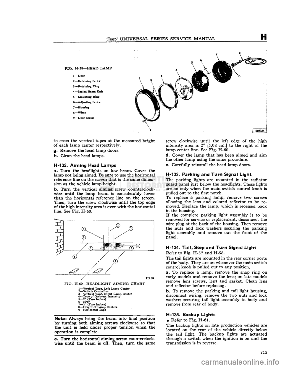
See Fig. H-60.
I
(T)
JT)
1'.'' | '':'
11460
FIG.
H-60—HEADLIGHT AIMING
CHART
1—
Vertical
Tape,
Left
Lamp
Center
2—
Vehicle
Centerline
3—
—Vertical
Tape,
Right
Lamp
Center
4—
Zone
of Greatest Intensity
5—
2
*
(Two Inches)
6— 25'0
'
7—
2
*
(Two Inches)
8—
Height
of
Lamp
Centers
9—
Horizontal
Tape
Note:
Always bring the beam into final position
by turning both aiming screws clockwise so that
the unit is held under proper tension when the operation is complete.
c. Turn
the horizontal aiming screw counterclock
wise until the beam is off.
Then,
turn
the same
screw
clockwise until the
left
edge
of the high
intensity area is 2" [5,08 cm.] to the right of the
lamp center line. See Fig. H-60.
d.
Cover the lamp that has been aimed and aim
the other lamp using the same procedure.
e.
Carefully
reinstall the head lamp doors.
H-133.
Parking
and
Turn Signal Light
The
parking lights are mounted in the radiator
guard
panel just below the headlights. These lights
are
on only when the main switch control knob is
pulled
out to the first notch.
To
replace a parking lamp, remove two screws allowing the lens and colored reflector to be re
moved. Replace the lamp, which is recessed back
in
the housing.
If
the
complete
parking light assembly is to be
removed for service or replacement, disconnect the
wire
plug at the back of the housing.
Then
remove
the nuts and lock washers securing the parking light assembly and remove out the front of the
panel.
H-134. Tail, Stop
and
Turn Signal Light
Refer
to Fig. H-57 and H-58.
The
tail
lights are mounted in the
rear
corner
posts
of the body. They are on whenever the main switch
control
knob is pulled out to any position.
a.
To replace a lamp, remove the snap ring on
early
models
and remove the lens; on late
models
remove lens screws, lens and gasket.
Clean
lens
and
reflector before replacing.
b. To remove the parking and
tail
light housing,
disconnect wiring, remove the two nuts and lock
washers securing
tail
light assembly to body and remove from
rear
of body.
H-135-
Backup Lights •
Refer to Fig. H-61.
The
backup lights on late production vehicles are located on the
rear
of the vehicle directly below
the
tail
light. The backup lights are actuated
through a switch when the ignition is on and the
transmission
is in reverse. 215