lights JEEP CJ 1953 User Guide
[x] Cancel search | Manufacturer: JEEP, Model Year: 1953, Model line: CJ, Model: JEEP CJ 1953Pages: 376, PDF Size: 19.96 MB
Page 174 of 376
H
ELECTRICAL
SYSTEM
the condenser. Replace the condenser. If there is
no jump to full voltage, overhaul or replace the
distributor.
k.
With the points closed, connect the voltmeter
from
a clean, paint-free
post
on the distributor
body to the negative
post
of the battery. The volt
age drop should be practically zero, a hardly
readable deflection on the voltmeter. If the volt meter registers a
voltage
drop, perform the checks
in
steps
1
and m following.
I.
Check
for
voltage
drop in the battery ground
cable.
Clean
the battery
post,
cable terminals, and contact surface on the bellhousing, or on body if
a
noticeable deflection of the voltmeter occurs,
m.
Check
for any
voltage
drop
between
the dis
tributor
body and a clean, paint-free
spot
on the
cylinder
block. If there is any
voltage
drop, remove
the distributor and clean the mounting surfaces of
distributor
body and cylinder block.
H-5.
SECONDARY
CIRCUIT
If
satisfactory ignition is not obtainable with cor
rect
point gap and tension; satisfactory condenser;
sufficient primary voltage; and correctly cleaned, gapped, and installed spark plugs; the secondary
circiut
should be investigated.
a.
Test the coil.
Bring
the coil up to operating
temperature using the coil heat feature of a coil tester, if available. Refer to the coil tester manu
facturer's
instructions for specific hook-ups for
performing the checks given in
steps
b, c, and d following.
b. Connect the positive lead of the tester to the
battery terminal of the coil primary winding.
Con
nect the tester ground lead to the coil tower. Mea
sure
the resistance of the secondary winding. If the
resistance is more than
20,000
ohms, a fault in the
secondary winding is indicated.
c.
Check
for a grounded secondary by touching the tester ground lead to the coil cover. If resistance
is not over
100,000
ohms, the secondary is grounded
to the cover.
d.
If the secondary winding is satisfactory, mea
sure
the primary current draw in accordance with
the instructions of the
test
equipment manu
facturer.
e.
Check
the secondary circuit for leakage. With the coil primary in the circuit with the breaker unit of the tester, connect a long, high-tension
test
lead
to the coil tower.
Check
the secondary circuit for
leakage by performing the checks given in
steps
f. g, h, and i following.
Note:
In the following
tests,
a slight sparking and
meter deflection
will
usually be
seen
just as contact
is made.
This
is caused by capacitance and
does
not
indicate defective insulation.
f.
Check
distributor cap. Remove the coil lead from the cap and touch the
test
lead to the center contact
inside the cap. If the meter reading drops when the contact is touched or if sparking is seen, a leakage
path is present
between
the center contact and one
of the plug towers.
This
leakage path
will
be in the
form
of a
crack
or carbon track in the cap. Discon nect the spark plug wires from the cap one at a
time and
test
each plug contact with the high-
voltage
lead and with all other plug wires con
nected. Any sparking or meter drop indicates that
a
leakage path exists
between
that particular con
tact and an adjacent one. Testing the adjacent contacts
will
determine which pair is at fault,
g-
Check
distributor rotor. Touch the
test
lead to
the spring contact in the center of the distributor
rotor.
Any leakage in the rotor insulation
between
the contact and the shaft
will
cause a drop in the meter reading and usually sparking
will
be seen.
h.
Check
spark plug wires. Disconnect the spark
plug wires from the plugs and
test
the plug terminal of each. The meter reading should not drop below
the open secondary value (value before making contact). If it
does
or if a large spark occurs when
the
test
lead and the plug wire are separated, there
is a break in the insulation on that wire.
i.
Check
the coil tower insulation. Remove the
high-tension
test
lead from the coil tower and touch
the ground lead of the coil tester to several points
around
the base of the tower. Any sparking or deflection of the meter indicates a leakage path in
the tower insulation.
H-6.
Alternator Charging System
All
Jeep
Universal
Series vehicles have, as standard
equipment a 35-amp., 12-volt, negative ground
alternator and a transistorized
voltage
regulator.
For
repairing the alternator, many of its major components are furnished as complete assemblies
including:
complete brush assembly which requires no soldering or unsoldering of leads; two complete
rectifying
diode
assemblies which eliminate the need for removing and replacing individual diodes;
a
complete isolation
diode
assembly; and a rotor assembly complete with shaft,
pole
pieces, field coil,
and
slip rings.
The
transistorized
voltage
regulator is an electronic
switching device. It
senses
the
voltage
appearing at the auxiliary terminal of the alternator and
supplies the necessary field current for maintaining the system
voltage
at the output
terminal.
The out
put current is determined by the battery electrical
load;
such as headlights, heater, etc.
The
transistorized
voltage
regulator is a sealed unit,
has no adjustments, and must be replaced as a
complete unit.
H-7.
Starting System
The
operation of the starter motor is controlled by
the ignition switch. The starter is made up of a
frame,
field coil, armature, and brushes.
The
starter solenoid electrically
closes
the circuit
between
the battery and the starter motor. When the ignition key is turned to its extreme right, the
solenoid is energized and
closes
the battery-to- starter-motor circuit.
Note:
All Jeep Universal Series vehicles have the
starter
solenoid switch secured to the starter motor
assembly. The Hurricane F4 and Dauntless V-6
engine
Prestolite starter drive is of the inertia type
(rexr
continued on
page
176) 174
Page 175 of 376
'Jeep'
UNIVERSAL
SERIES
SERVICE
MANUAL
H
11514
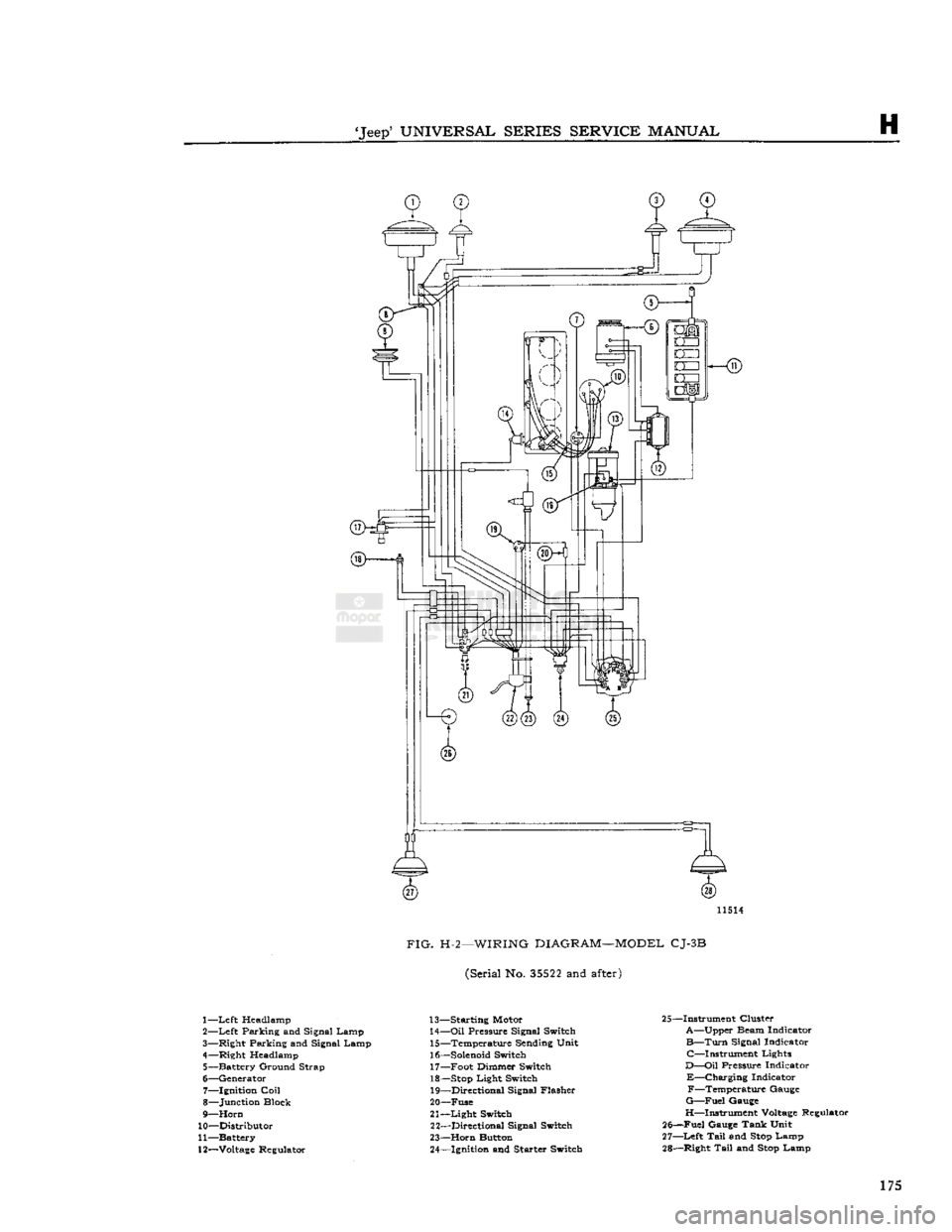
FIG.
H-2—WIRING
DIAGRAM—MODEL
CJ-3B
(Serial No.
35522
and
after)
1—
Left
Headlamp
2—
Left
Parking and Signal Lamp
3— Right Parking and Signal Lamp
4— Right Headlamp 5— Battery Ground Strap
6— Generator 7— Ignition
Coil
8— Junction Block
9—
Horn
10— Distributor
11— Battery
12—
Voltage
Regulator 13— Starting Motor
14—
Oil
Pressure Signal Switch 15— Temperature Sending Unit
16—
Solenoid
Switch 17— Foot Dimmer Switch
18—
Stop
Light Switch 19— Directional Signal Flasher
20— Fuse
21—
Light
Switch 22— Directional Signal Switch
23—
Horn
Button 24— Ignition and Starter Switch 25—Instrument Cluster
A—Upper Beam Indicator
B—Turn
Signal Indicator C—Instrument Lights
D—Oil
Pressure Indicator
E—Charging
Indicator F—Temperature Gauge
G—Fuel
Gauge
H—Instrument
Voltage
Regulator
25—Fuel Gauge Tank Unit
27—
Left
Tail
and
Stop
Lamp
28— Right
Tail
and
Stop
Lamp 175
Page 176 of 376
H
ELECTRICAL
SYSTEM
11474
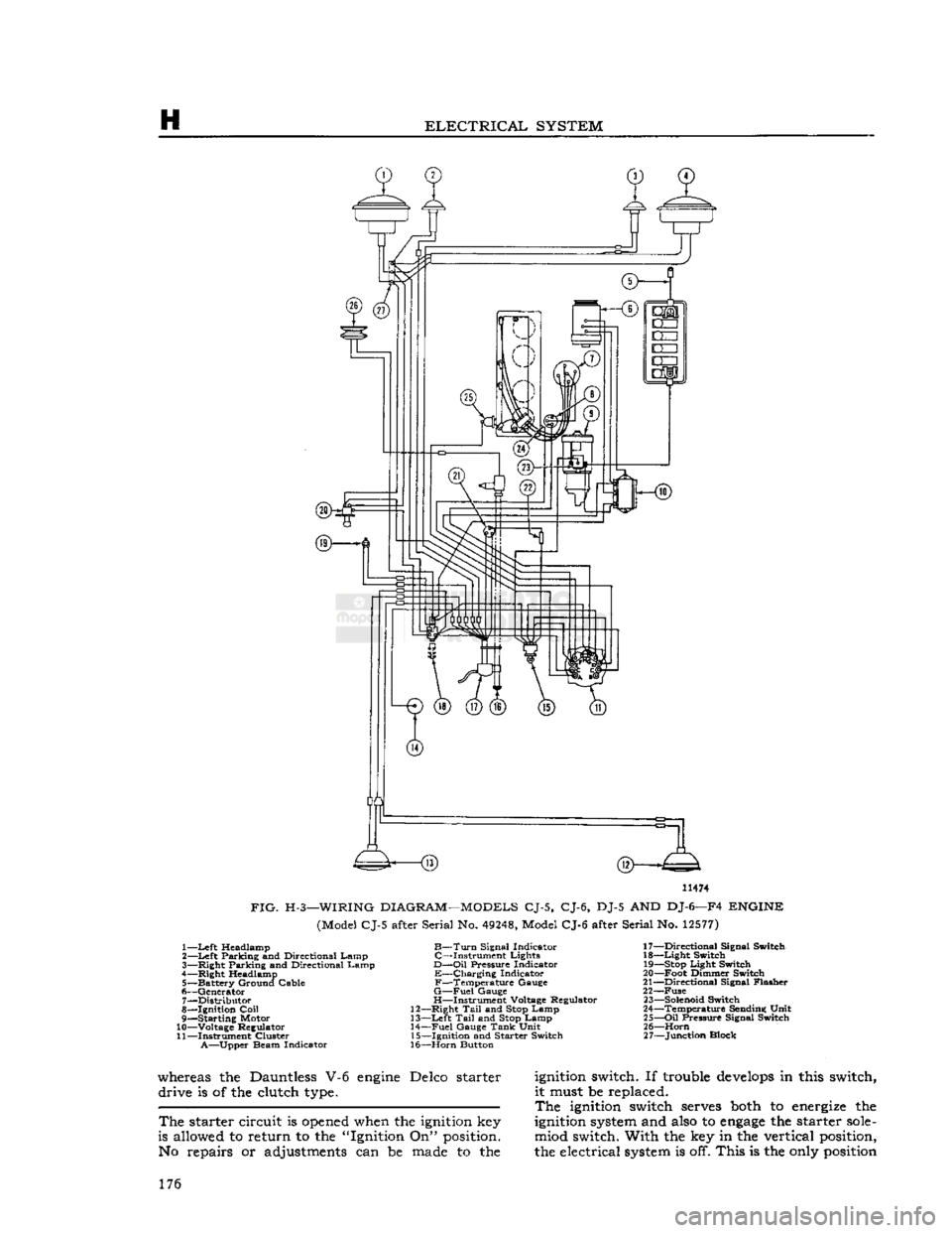
FIG.
H-3—WIRING
DIAGRAM—MODELS
CJ-5, CJ-6, DJ-5 AND DJ-6—F4
ENGINE
(Model CJ-5 after Serial No.
49248,
Model CJ-6 after Serial No.
12577)
1—
Left
Headlamp
B—Turn
Signal Indicator 17—Directional Signal Switch
2—
Left
Parking and Directional Lamp C—Instrument Lights 18—Light Switch
3— Right Parking and Directional Lamp
D—Oil
Pressure Indicator
19—Stop
Light Switch
4— Right Headlamp E—Charging Indicator 20—Foot Dimmer Switch
5— Battery Ground Cable F—Temperature Gauge 21—Directional Signal Flasher
6— Generator
G—Fuel
Gauge 22—Fuse 7— Distributor H—Instrument Voltage Regulator
23—Solenoid
Switch
8— Ignition
Coil
12—Right
Tail
and
Stop
Lamp 24—Temperature Sending Unit
9— Starting Motor 13—Left
Tail
and
Stop
Lamp 25—Oil Pressure Signal Switch
10— Voltage Regulator 14—Fuel Gauge
Tank
Unit 26—Horn
11— Instrument Cluster 15—Ignition and Starter Switch 27—Junction Block
A—Upper
Beam Indicator 16—Horn Button
whereas the Dauntless V-6
engine
Delco starter
ignition
switch. If trouble
develops
in this switch, drive is of the clutch
type.
it must be replaced.
The
ignition
switch
serves
both
to
energize
the
The
starter circuit is
opened
when the
ignition
key
ignition
system
and
also
to
engage
the starter
sole-
is allowed to return to the "Ignition On"
position.
miod switch. With the key in the vertical
position,
No repairs or adjustments can be
made
to the the electrical
system
is off. This is the
only
position
176
Page 177 of 376
'Jeep*
UNIVERSAL
SERIES
SERVICE
MANUAL
H
12968
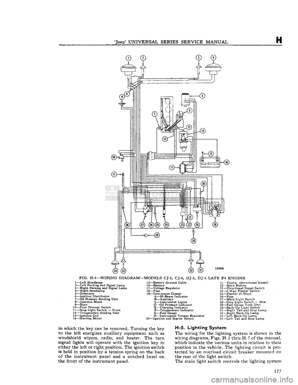
FIG.
H-4—WIRING
DIAGRAM—MODELS
CJ-5, CJ-6, DJ-5, DJ-6
LATE
F4
ENGINE
1—
Left
Headlamp
2—
Left
Parking and Signal Lamp
3— Right Parking and Signal Lamp 4— Right Headlamp
5— Generator
6— Ignition Distributor
7—
Oil
Pressure Sending Unit
8— Junction Block
9—
Horn
10— Foot Dimmer Switch 11—
Stop
Light Switch — Front
12— Temperature Sending Unit
13— Ignition
Coil
14— Starting Motor 15— Battery Ground Cable
16— Battery
17— Voltage Regulator 18—
Fuse
19— Instrument Cluster
A—Hi-Beam
Indicator
B—Auxiliary
C—Instrument
Lights
D—Oil
Pressure Indicator
E—Charging
Indicator
F—Temperature
Indicator
G—Fuel
Gauge
H—Instrument Voltage Regulator
20— Ignition and Starter Switch 21—
Flashei
(Directional Signal)
22—
Horn
Button 23— Directional Signal Switch
24— 4-Way Flasher Switch
25—
Flasher
(4-Way)
26—
Fuse
27—
Main
Light Switch 28—
Stop
Light Switch — Rear
29—
Fuel
Gauge
Tank
Unit
30—
Back-Up
Light Switch
31— Right
Tail
and
Stop
Lamp
32— Right Back-Up Lamp
33—
Left
Back-Up Lamp
34—
Left
Tail
and
Stop
Lamp
in
which the key can be removed. Turning the key
to the
left
energizes
auxiliary
equipment
such as
windshield wipers, radio, and heater. The turn
signal
lights
will
operate
with the
ignition
key in
either the
left
or right
position.
The
ignition
switch is held in
position
by a
tension
spring on the back
of the instrument panel and a
notched
bezel on
the front of the instrument panel.
H-8.
Lighting System
The
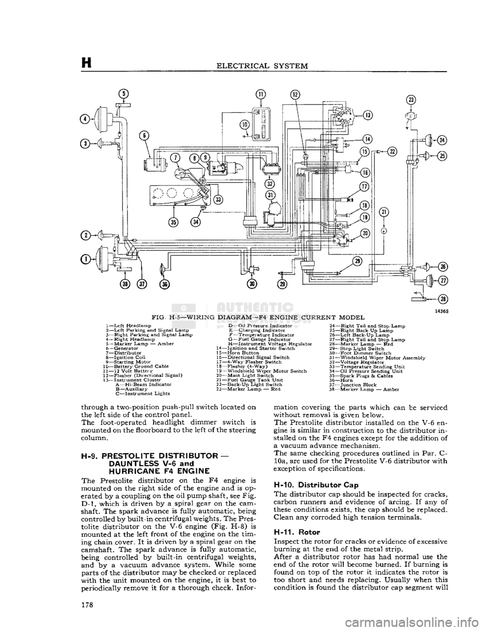
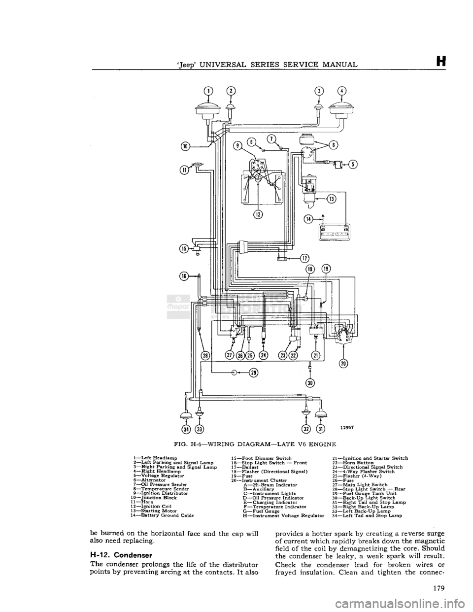
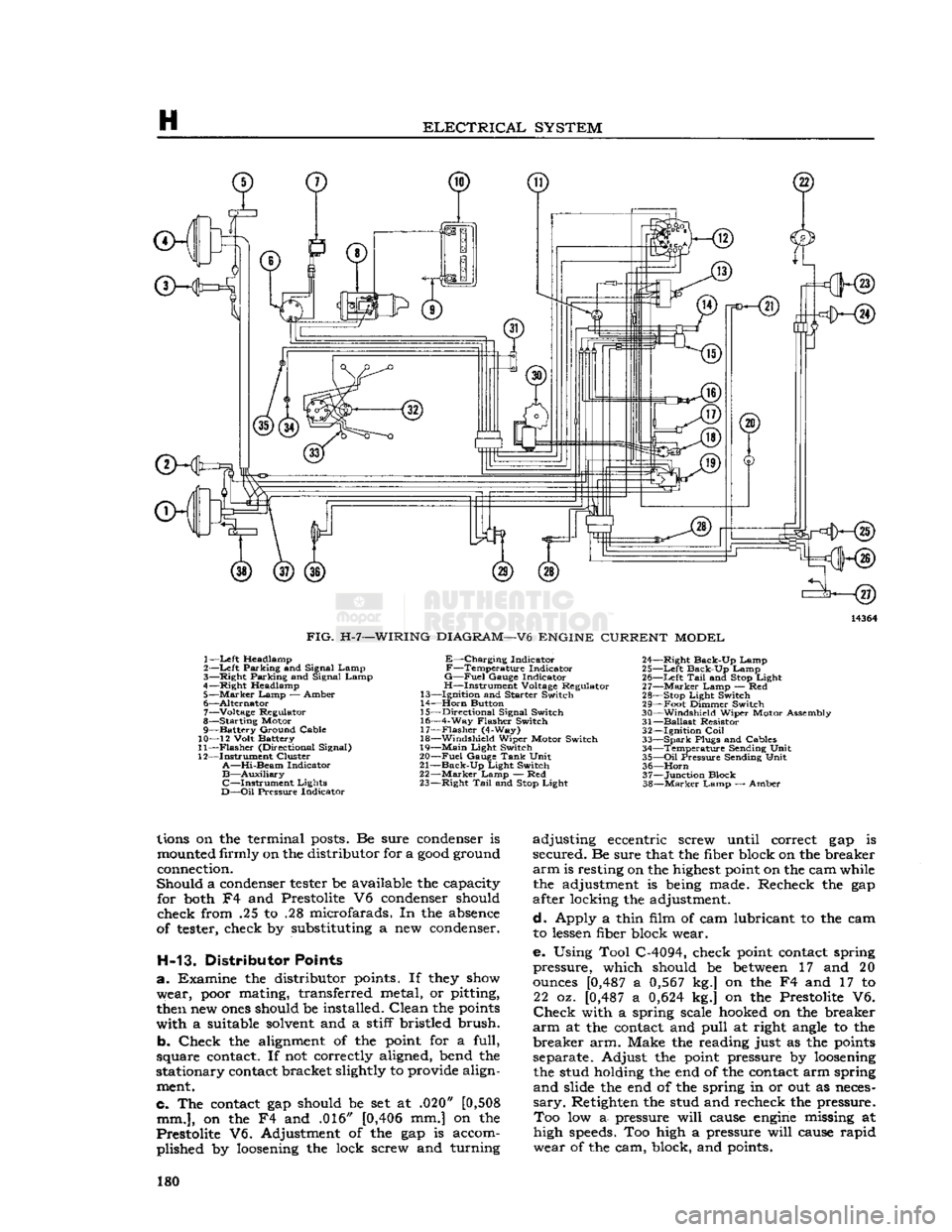
wiring for the lighting
system
is shown in the
wiring diagrams, Figs. H-2 thru H-7 of the manual,
which indicate the various units in relation to their
position
in the vehicle. The lighting circuit is pro
tected
by an overload circuit breaker
mounted
on the rear of the light switch.
The
main light switch controls the lighting
system
177
Page 178 of 376
H
ELECTRICAL
SYSTEM
14365
FIG.
H-5—WIRING
DIAGRAM—F4
ENGINE
CURRENT
MODEL
1—
Left
Headlamp
2—
Left
Parking and Signal Lamp
3—
Right
Parking and Signal Lamp
4—
Right
Headlamp
5—
Marker
Lamp
— Amber
6—
Generator
7—
Distributor
8—
Ignition
Coil
9— Starting Motor
10— Battery Ground Cable
11—
12
Volt
Battery
12—
Flasher
(Directional Signal)
13— Instrument Cluster
A—Hi-Beam
Indicator
B—Auxiliary
C—Instrument Lights
D—Oil
Pressure
Indicator
E—Charging Indicator
F—Temperature Indicator
G—Fuel
Gauge
Indicator
H—Instrument Voltage Regulator
14—
Ignition
and
Starter
Switch
15—
Horn
Button 16—
Directional
Signal Switch 17— 4-Way
Flasher
Switch
18—
Flasher
(4-Way)
19—
Windshield
Wiper Motor Switch
20—
Main
Light
Switch
21—
Fuel
Gauge
Tank
Unit
22—
Back-Up
Light
Switch
23—
Marker
Lamp — Red 24—
Right
Tail
and Stop Lamp
25—
Right
Back-Up Lamp
26—
Left
Back-Up Lamp
27—
Right
Tail
and Stop Lamp
28—
Marker
Lamp — Red 29— Stop
Light
Switch
30— Foot Dimmer Switch
31—
Windshield
Wiper Motor Assembly
32—
Voltage Regulator
33— Temperature Sending
Unit
34—
Oil
Pressure
Sending
Unit
35— Spark
Plugs
&
Cables
36—
Horn
37— Junction Block
38—
Marker
Lamp — Amber
through a
two-position
push-pull switch located on
the
left
side
of the control panel.
The
foot-operated
headlight dimmer switch is
mounted on the floorboard to the
left
of the steering
column.
H-9.
PRESTOLITE
DISTRIBUTOR
—
DAUNTLESS
V-6 and
HURRICANE
F4
ENGINE
The
Prestolite distributor on the F4
engine
is
mounted on the right
side
of the
engine
and is op
erated by a coupling on the oil pump shaft, see Fig.
D-l,
which is driven by a spiral gear on the cam
shaft. The spark advance is fully automatic, being controlled by built-in centrifugal
weights.
The Pres
tolite
distributor on the V-6
engine
(Fig. H-8) is mounted at the
left
front of the
engine
on the tim
ing chain cover. It is driven by a spiral gear on the
camshaft. The spark advance is fully automatic,
being controlled by built-in centrifugal
weights,
and by a vacuum advance system. While
some
parts of the distributor may be checked or replaced
with the unit mounted on the
engine,
it is
best
to periodically remove it for a thorough check. Infor mation covering the parts which can be serviced
without removal is
given
below.
The
Prestolite distributor installed on the V-6 en
gine
is similar in construction to the distributor in
stalled on the F4
engines
except
for the addition of
a
vacuum advance mechanism.
The
same checking procedures outlined in Par. C- 10a, are used for the Prestolite V-6 distributor with
exception
of specifications.
H-10. Distributor Cap
The
distributor cap should be inspected for cracks,
carbon runners and
evidence
of arcing. If any of
these
conditions
exists, the cap should be replaced.
Clean
any corroded high
tension
terminals.
H-11.
Rotor
Inspect the rotor for cracks or
evidence
of
excessive
burning at the end of the metal strip.
After a distributor rotor has had normal use the
end of the rotor will
become
burned. If burning is found on top of the rotor it indicates the rotor is
too short and
needs
replacing. Usually when this condition is found the distributor cap
segment
will 178
Page 179 of 376
'Jeep'
UNIVERSAL
SERIES
SERVICE
MANUAL
H
12967
FIG.
H-6—WIRING
DIAGRAM—LATE
V6
ENGINE
1—Left Headlamp
2—
Left
Parking and Signal Lamp
3—
Right
Parking and Signal Lamp
4—
Right
Headlamp
5— Voltage Regulator
6—
Alternator
7—
Oil
Pressure
Sender
8— Temperature
Sender
9—
Ignition
Distributor
10— Junction Block
11—
Horn
12—
Ignition
Coil
13— Starting Motor
14— Battery Ground Cable 15— Foot Dimmer Switch 21-
16— Stop
Light
Switch — Front 22-
17— Ballast 23-
18—
Flasher
(Directional Signal) 24-
19—
Fuse
25-
20— Instrument Cluster 26-
A—Hi-Beam
Indicator 27-
B—Auxiliary
28- C—Instrument Lights 29-
D—Oil
Pressure
Indicator 30-
E—Charging Indicator 31-F—Temperature Indicator 32-
G—Fuel
Gauge
33-
H—Instrument Voltage Regulator 34-
-Ignition
and
Starter
Switch
-Horn
Button
-Directional
Signal Switch
-4-Way
Flasher
Switch
-Flasher
(4-Way)
-Fuse
-Main
Light
Switch
-Stop
Light
Switch —
Rear
-Fuel
Gauge
Tank
Unit
-Back-Up
Light
Switch
-Right
Tail
and Stop Lamp
-Right
Back-Up Lamp
-Left
Back-Up Lamp
-Left
Tail
and Stop Lamp
be burned on the horizontal
face
and the cap will
also
need
replacing. H-12. Condenser
The
condenser
prolongs
the
life
of the distributor
points
by
preventing
arcing at the
contacts.
It
also
provides
a
hotter
spark by creating a reverse
surge
of current which rapidly breaks
down
the
magnetic
field of the coil by
demagnetizing
the core. Should
the
condenser
be leaky, a weak spark will result.
Check
the
condenser
lead for broken wires or
frayed insulation. Clean and
tighten
the
connec-
179
Page 180 of 376
H
ELECTRICAL
SYSTEM
ffKHs)
3—<§)
FIG.
H-7—WIRING
DIAGRAM—V6
ENGINE
CURRENT
MODEL
1—
Left
Headlamp
2—Left Parking and Signal Lamp
3— Right Parking and Signal Lamp
4—Right Headlamp 5—
Marker
Lamp — Amber
6— Alternator 7— Voltage Regulator
8— Starting Motor
9— Battery Ground Cable
10— 12 Volt Battery
11—
Flasher
(Directional Signal)
12— Instrument Cluster
A—Hi-Beam
Indicator
B—Auxiliary
C—Instrument
Lights
D—Oil
Pressure Indicator
E—Charging
Indicator
F—Temperature
Indicator
G—Fuel
Gauge Indicator
H—Instrument Voltage Regulator
13— Ignition and Starter Switch
14—
Horn
Button
15— Directional Signal Switch
16— 4-Way Flasher Switch 17—
Flasher
(4-Way)
18— Windshield Wiper Motor Switch
19—
Main
Light Switch
20—
Fuel
Gauge
Tank
Unit
21—
Back-Up
Light Switch
22—
Marker
Lamp — Red
23— Right
Tail
and
Stop
Light 24— Right Back-Up Lamp
25—
Left
Back-Up Lamp 26—
Left
Tail
and
Stop
Light
27—
Marker
Lamp — Red
28—
Stop
Light Switch
29— Foot Dimmer Switch
30— Windshield Wiper Motor Assembly
31—
Ballast
Resistor 32— Ignition
Coil
33—
Spark
Plugs and Cables 34— Temperature Sending Unit
35—
Oil
Pressure Sending Unit 36—
Horn
37— Junction Block
38—
Marker
Lamp — Amber
lions
on the terminal
posts.
Be sure
condenser
is
mounted
firmly on the distributor for a
good
ground
connection.
Should a
condenser
tester
be available the capacity for
both
F4 and Prestolite V6
condenser
should
check from .25 to .28 microfarads. In the
absence
of
tester,
check by substituting a new
condenser.
H-13. Distributor Points
a. Examine the distributor
points.
If
they
show
wear,
poor
mating, transferred metal, or pitting,
then
new
ones
should be installed. Clean the
points
with a suitable
solvent
and a stiff bristled brush.
b. Check the
alignment
of the
point
for a full,
square
contact.
If not correctly aligned, bend the
stationary
contact
bracket slightly to provide align
ment.
c. The
contact
gap should be set at .020"
[0,508
mm.],
on the F4 and .016"
[0,406
mm.] on the
Prestolite V6. Adjustment of the gap is accom plished by
loosening
the lock screw and turning adjusting eccentric screw until correct gap is
secured. Be sure that the fiber block on the breaker
arm
is resting on the
highest
point
on the cam while the adjustment is
being
made. Recheck the gap
after locking the adjustment.
d. Apply a thin film of cam lubricant to the cam to
lessen
fiber block wear.
e. Using Tool C-4094, check
point
contact
spring
pressure, which should be
between
17 and 20
ounces
[0,487
a
0,567
kg.] on the F4 and 17 to 22 oz.
[0,487
a
0,624
kg.] on the Prestolite V6.
Check
with a spring scale
hooked
on the breaker
arm
at the
contact
and pull at right
angle
to the
breaker arm. Make the reading just as the
points
separate. Adjust the
point
pressure by
loosening
the stud holding the end of the
contact
arm spring
and slide the end of the spring in or out as
neces
sary.
Retighten the stud and recheck the pressure. Too low a- pressure will
cause
engine
missing at
high
speeds.
Too high a pressure will
cause
rapid
wear of the cam, block, and
points.
180
Page 188 of 376
H
ELECTRICAL
SYSTEM
colder plug may be desirable. However, under- or
over-heating is usually caused by factors other than the type of
spark
plugs and the cause should be determined before changing plugs. The design of the
engine
calls for plugs equivalent to Champion
J-8
for F4
engines
and
A.C.
44S or
UJ12Y
Champ
ion for the V6 engines, (as installed in production)
though any factor that consistently affects
engine
operating temperature may cause this requirement
to change. Overheating may be caused by in sufficient tightening of the plug in the head, which interferes with the flow of heat away from the firing
tip.
If this is the case, the plug gasket
will
show very
little flattening. Over-tightening, in
turn,
will
pro duce too easy a heat flow path and result in cold
plug operation.
This
will
be evident by excessive
flattening
and
deformation of the gasket.
Prevailing
temperatures, condition of the cooling system, and
air-fuel
mixture can affect the
engine
operating temperature and should be taken into consideration.
H-34.
GENERATOR
— F4
ENGINE
The
generator is an air-cooled, two-brush unit
which
cannot be adjusted to increase or decrease output. For replacement,
voltage
regulator and generator must be matched for
voltage
and capa
city,
polarity, and common source of manufacture.
Otherwise,
either a
loss
of ampere capacity or a
burned
out generator
will
result. Generators for
these
vehicles are 12-volt. Par. H-l explains the 12-volt system. Refer to the specifications at the
end of this section for information on correct generator rating for a specific model series.
The
circuit
breaker,
voltage
regulator, and current-
limiting
regulator are built into one combination
unit.
Because the regulator and battery are part
of the generator
circuit,
the output of the generator
depends upon the
state
of charge and temperature
of the battery.
With
a discharged battery, the
output
will
be high, decreasing proportionally as the battery
becomes
charged. For service informa
tion covering current regulator see Par. H-41.
H-36.
Generator
Maintenance
A
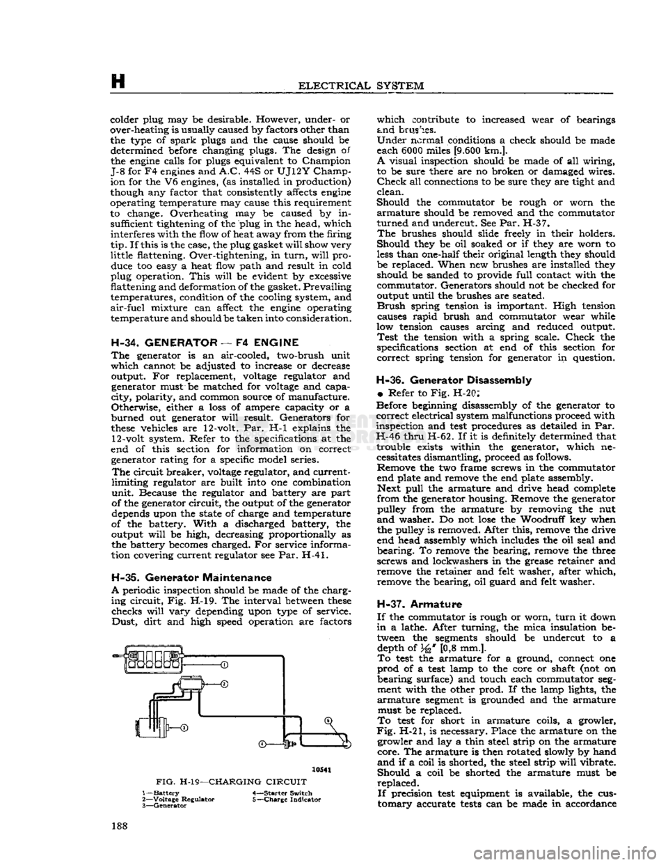
periodic inspection should be made of the charg
ing
circuit,
Fig. H-l9. The interval
between
these
checks
will
vary
depending upon type of service.
Dust,
dirt
and high speed operation are factors 10541
FIG.
H-19—CHARGING
CIRCUIT
1—
Battery
4-—Starter Switch
2—
Voltage
Regulator 5-—Charge Indicator
3—
Generator
which
contribute to increased wear of bearings
and
brushes.
Under
normal conditions a check should be made
each 6000 miles
[9.600
km.].
A
visual inspection should be made of all wiring,
to be sure there are no broken or damaged wires.
Check
all connections to be sure they are tight and
clean.
Should
the commutator be rough or worn the
armature
should be removed and the commutator
turned
and undercut. See Par. H-37.
The
brushes should slide freely in their holders.
Should
they be oil soaked or if they are worn to
less
than one-half their original length they should
be replaced. When new brushes are installed they should be sanded to provide
full
contact with the
commutator. Generators should not be checked for
output until the brushes are seated.
Brush
spring tension is important. High tension causes
rapid
brush and commutator wear while
low tension causes arcing and reduced output.
Test
the tension with a spring scale.
Check
the
specifications section at end of this section for
correct
spring tension for generator in question.
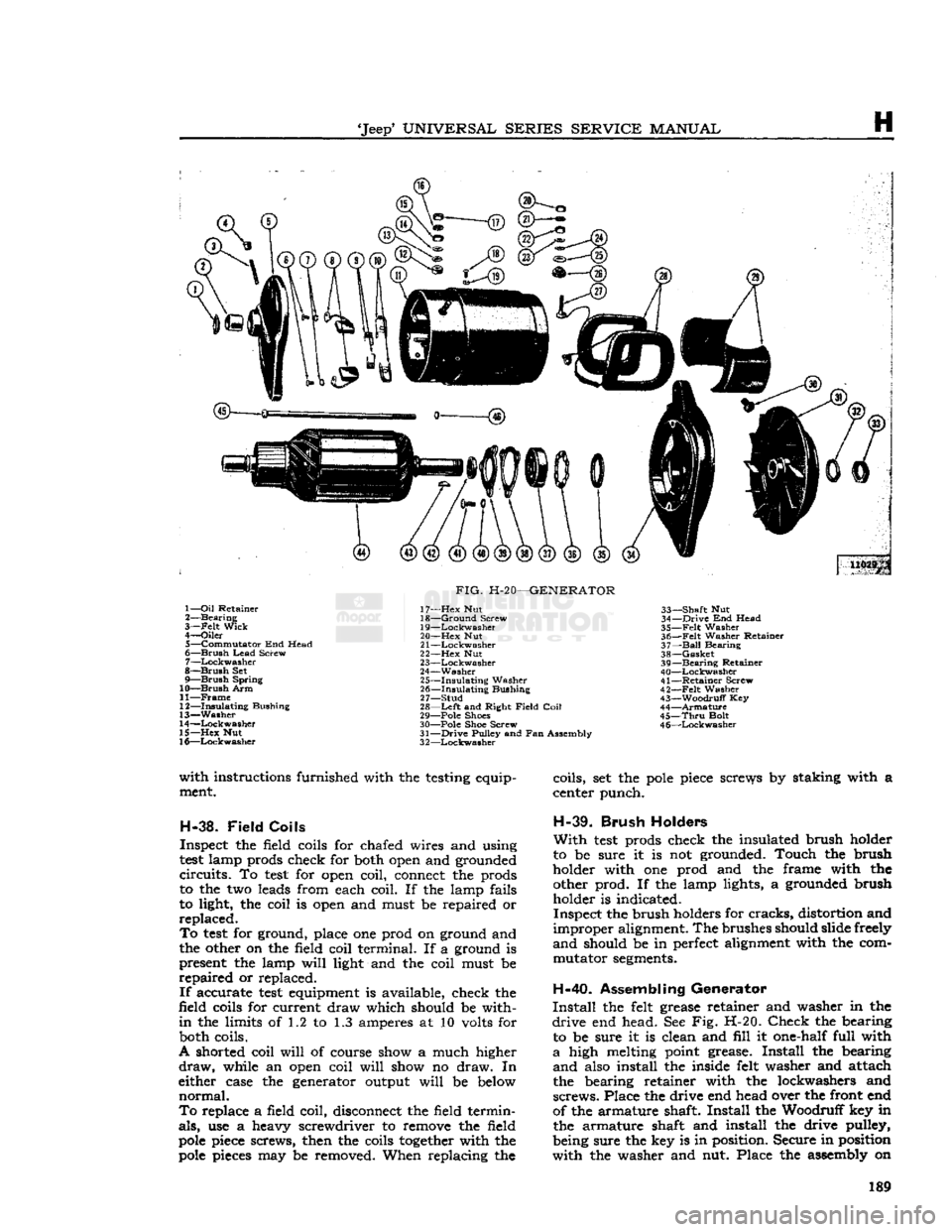
H-36.
Generator Disassembly
•
Refer to Fig. H-20:
Before beginning disassembly of the generator to
correct
electrical system malfunctions proceed with
inspection and
test
procedures as detailed in Par.
H-46
thru
H-62. If it is definitely determined that trouble exists within the generator, which necessitates dismantling, proceed as follows. Remove the two frame screws in the commutator
end plate and remove the end plate assembly. Next
pull
the armature and drive head complete
from
the generator housing. Remove the generator pulley from the armature by removing the nut
and
washer. Do not
lose
the Woodruff key when
the pulley is removed. After this, remove the drive
end head assembly which includes the oil seal and
bearing.
To remove the bearing, remove the three
screws and lockwashers in the grease retainer and remove the retainer and felt washer, after which,
remove the bearing, oil guard and felt washer.
H-37.
Armature
If
the commutator is rough or worn,
turn
it down
in
a lathe. After turning, the mica insulation be tween the
segments
should be undercut to a depth of 34* [0,8 mm.].
To
test
the armature for a ground, connect one
prod
of a
test
lamp to the core or shaft (not on
bearing
surface) and touch each commutator
seg
ment with the other prod. If the lamp lights, the
armature
segment
is grounded and the armature must be replaced.
To
test
for short in armature coils, a growler,
Fig.
H-21, is necessary. Place the armature on the growler and lay a thin steel strip on the armature
core.
The armature is then rotated slowly by hand
and
if a coil is shorted, the steel strip
will
vibrate.
Should
a coil be shorted the armature must be
replaced.
If
precision
test
equipment is available, the cus
tomary
accurate
tests
can be made in accordance 188
Page 189 of 376
'Jeep'
UNIVERSAL
SERIES
SERVICE
MANUAL
H
U029p 1—
Oil
Retainer
2—
Bearing
3—
-Felt
Wick
4—
Oiler
5—
Commutator
End Head
6—
Brush
Lead
Screw
7—
Lockwasher
8—
Brush
Set
9—
Brush
Spring
10—
Brush
Arm
11—
Frame
12—
Insulating
Bushing
13—
Washer
14—
Lockwasher
15—
Hex
Nut
16—
Lockwasher
FIG.
H-20—GENERATOR
17—
Hex
Nut
18—
Ground
Screw
19—
Lockwasher
20—
Hex
Nut
21
—Lockwasher
22—
Hex
Nut
23—
Lockwasher
24—
Washer
25—
Insulating
Washer
26—
Insulating
Bushing
27—
Stud
28—
Left
and Right
Field
Coil
29— Pole Shoes
30— Pole Shoe Screw
31—
Drive
Pulley and Fan Assembly
3
2—Lockwasher
33—
Shaft
Nut
34—
Drive
End Head
35—
Felt
Washer
36—
Felt
Washer Retainer
37—
Ball
Bearing
38—
Gasket
39—
Bearing
Retainer
40—
Lockwasher
41—
Retainer
Screw
42—
-Felt
Washer
43—
Woodruff
Key
44—
Armature
45—
Thru
Bolt
4
6—Lockwasher
with
instructions furnished with the testing equip ment.
H-38.
Field
Coils
Inspect the field coils for chafed wires and using
test
lamp prods check for both open and grounded
circuits.
To
test
for open coil, connect the prods
to the two leads from each coil. If the lamp fails
to light, the coil is open and must be repaired or
replaced.
To
test
for ground, place one prod on ground and
the other on the field coil terminal. If a ground is present the lamp
will
light and the coil must be
repaired
or replaced.
If
accurate
test
equipment is available, check the
field coils for current draw which should be with
in
the limits of 1.2 to 1.3 amperes at 10 volts for both coils.
A shorted coil
will
of course show a much higher
draw,
while an open coil
will
show no draw. In
either case the generator output
will
be below
normal.
To
replace a field coil, disconnect the field termin
als,
use a heavy screwdriver to remove the field
pole
piece screws, then the coils
together
with the
pole
pieces may be removed. When replacing the coils, set the
pole
piece screws by staking with a
center punch.
H-39.
Brush
Holders
With
test
prods check the insulated brush holder
to be sure it is not grounded. Touch the brush
holder with one prod and the frame with the other prod. If the lamp lights, a grounded brush holder is indicated.
Inspect the brush holders for
cracks,
distortion and
improper
alignment. The brushes should slide freely
and
should be in perfect alignment with the com mutator
segments.
H-40.
Assembling Generator
Install
the felt grease retainer and washer in the
drive
end head. See Fig. H-20.
Check
the bearing to be sure it is clean and
fill
it one-half full with
a
high melting point grease.
Install
the bearing
and
also install the inside felt washer and attach
the bearing retainer with the lockwashers and
screws.
Place the drive end head over the front end
of the armature shaft.
Install
the Woodruff key in the armature shaft and install the drive pulley,
being sure the key is in position. Secure in position
with
the washer and nut. Place the assembly on 189
Page 191 of 376
'Jeep*
UNIVERSAL SERIES SERVICE
MANUAL
H
long as the circuit values allow the voltage to build
up to the operating voltage.
The
electromagnet of the voltage regulator unit has
a
winding of many turns of fine wire and is con
nected across the charging circuit so that the sys tem voltage controls the amount of magnetism.
The
contacts of the voltage regulator unit are con
nected in the generator field circuit so that the field
circuit
is completed through the contacts when they
are
closed and through a resistor when the contacts
are
opened.
When
the voltage rises to a predetermined value
there is sufficient magnetism created by the regu
lator
winding to
pull
the
armature
down.
This
opens
the contacts and inserts resistance in the field
cir
cuit
of the generator thus reducing the
field
current.
The
generated voltage immediately drops, which
reduces the
pull
on the
armature
to the point where
the spring closes the contacts. The output again
rises
and the cycle is repeated.
These
cycles occur at high enough frequencies to
hold the generated voltage at a constant value and
will
continue as long as the voltage of the circuit
is high enough to keep the voltage regulator unit
in
operation.
With
the addition of a current load great enough to lower the battery voltage below
the operating voltage of the unit, the contacts
will
remain
closed and the generator
will
maintain a
charging
rate as limited by its speed or the current
limiting
regulator.
Due
to the
effect
of heat on the operating
charac
teristics of regulator windings it is necessary to
compensate for the changes in coil resistance when
the regulator is operating under varying tempera
ture
conditions.
This
is accomplished through the
use of a nickel iron magnetic by-pass on the volt
age regulator unit.
This
shunt by-passes
some
of
the magnetic flux when the unit is cold and allows most of the flux to act on the armature when the
unit
is hot.
Thus
when the coil is hot and not as
efficient, the magnetic shunt reduces the amount of flux needed to vibrate the armature.
The
compensation is usually more than enough to
offset
the changes in regulator coil resistance due
to heat. The excess compensation allows the regu
lator
to operate at higher voltage under cold
operating conditions than under hot conditions.
This
is necessary as it requires a higher voltage to charge a battery with its internal resistance in
creased
by low temperatures.
H-45.
Current-Limiting
Regulator
The
function of the current-limiting regulator is to limit the output of the generator to its maxi
mum
safe output.
The
electromagnet of the current regulator unit
consists of
a
winding of heavy
wire
that is connected
in
series with the generator output. When the gen
erator
output reaches a predetermined value, the
current
in the winding produces enough magnetism
to overcome the spring tension and
pull
the
arma
ture
down.
This
opens
the contacts and inserts re
sistance in the field circuit of the generator.
With
the field current reduced by the resistance, the
generator output falls and there is no longer enough
magnetism to hold the contacts open. As soon as
the spring closes the contacts, the output rises and the cycle is repeated. These cycles occur at high
enough frequencies to limit the output to a mini
mum
fluctuation.
H-46.
Preliminary Inspection
a.
Wiring—Check
the wiring to see that it is prop
erly
connected to the generator.
b.
Generator
Performance—Make
sure the genera
tor operates correctly without the regulator in the
circuit.
Remove the armature and battery leads
from
the regulator and connect an ammeter be
tween them. Remove the field lead from the regu
lator
and while operating at idle speed touch the
field
lead
to the regulator base. Increase the speed slowly noting the charging rate.
CAUTION:
Do not increase the output above
the rated output of the generator.
If
the generator output
will
not build up inspect
the wiring harness for shorts and
opens
and remove the generator for an overhaul. To check the genera
tor circuit when a suitable ammeter is unavailable,
Fig.
H-19, disconnect the armature cable at the
regulator.
Connect one lead of
a
12v
test
lamp to the regulator terminal marked "armature" and with
the engine running, ground the other lead. Should
the
test
light
fail
to
burn
there is a fault either in the generator or regulator. To localize the fault, discon
nect both the
"Field"
and
"Armature"
cables at the generator. Connect a wire from the
"Field"
ter
minal
to ground and use a 60 watt, 110 volt
test
lamp
to ground the
"Armature"
terminal. If the
generator is charging satisfactorily the
test
lamp
will
glow
at approximately 1500 rpm. engine speed
and
the fault
will
be definitely localized in the
regulator.
c.
Incorrect Regulator—Make sui he regulator
is the correct type for use with the generator.
d.
Battery—Check
the specific gravity and termi
nal
voltage of the battery. If the \ ttery is not up
to specifications substitute temporarily
for
test
pur
poses
a fully charged battery of the same type and
capacity.
e. High Resistance Connections—Inspect the
wir
ing between the generator, regulator and battery for broken wires and high resistance connections.
Pay
special attention to the ground connections at
all
three units. Connect a reliable ammeter with 1-ampere graduations in series with the regulator
B-terminal
and the lead removed from this
terminal.
Run
the generator at a medium speed and
turn
on the lights or accessories until the ammeter shows a 10-ampere charging rate. At this charging rate
measure the voltage drop between the following
points using an accurate voltmeter graduated in
,1-volt divisions. The voltmeter should not show
a
reading above the maximum noted.
Generator
"A" terminal to regulator
"A"
terminal
—.1-volt maximum.
Generator
"F"
terminal to regulator
"F"
terminal
—.05-volt maximum.
Battery
terminal to regulator "B" terminal— .1-volt maximum.
Regulator
ground screw to generator frame— .03-volt maximum. 191