lights JEEP CJ 1953 Owner's Guide
[x] Cancel search | Manufacturer: JEEP, Model Year: 1953, Model line: CJ, Model: JEEP CJ 1953Pages: 376, PDF Size: 19.96 MB
Page 217 of 376
'Jeep'
UNIVERSAL
SERIES
SERVICE
MANUAL
H
cuit
lights,
the
signal switch
is
inoperative
and
must
be
replaced.
H-139.
Hazard
Warning Lights
All
current production vehicles
are
equipped with
a
four-way flasher warning system.
The
control switch
is
located
on the
instrument panel left
of
the steering column.
With
the
switch pulled
out,
the
two
front and
two
rear
turn
signal lights flash
on and
off
simultaneously,
as do
both
turn
signal
indicator
lights
on the
instrument clusters.
H-140.
Marker
Lights and Reflector Assembly
The
marker
lights
and
reflector assemblies
on
current
production vehicles
are
mounted
on the
side
of
the front fender and
on the
side
of
the
rear
quarter
panel.
The
spare wheel also mounts
a
marker
light. Some earlier production vehicles have
reflex reflectors mounted on the side of the hood and
on
the
side
of
the
rear
quarter panel. determine
if
dash wiper switch or wiring
is at
fault,
disconnect wiring harness from wiper motor
and
try
operating wiper independently
of
dash switch.
If
still
inoperative
see
procedure under
Par.
H-145.
b. Wiper
will
not
shut
off
— Determine
if
wiper
has both
low
and high speeds, slow speed only,
or
high speed only.
It is
important that
the
wiper
operates
at low
speed during parking cycle.
Dis
connect wiring harness from wiper motor
and try
operating wiper independently
of
dash switch.
If
wiper
shuts
off
correctly with
crank
arm
in
park
position and wiper has both speeds, check
the
lead
between
terminal
and
dash switch ground
and
check
for
defective dash switch.
If
wiper shuts
off
correctly,
but has
high speed only, check lead
be
tween wiper terminal and dash switch
for an
open
circuit
and check
for
defective dash switch.
If
still
inoperative,
see
Par. H-145.
c. Wiper
has
only fast speed.
Check
for
defective dash switch
or
open lead
between
terminal
and
dash switch.
H-141.
Windshield Wiper System
Early
production vehicles equipped with
the
Dauntless V-6
engine
have
two
single speed wind
shield wiper motors mounted above
the
windshield inside
the
vehicle. The wiper motors
are
operated
and
controlled
by a
switch located
on the
instru
ment panel.
Current
production vehicles with stationary wind
shield have
a
two-speed
electric windshield wiper motor mounted below
the
windshield outside
the
vehicle on the driver's side. The wiper motor switch is located
on the
instrument panel
to the
left
of
the steering column.
H-142.
Two-Speed Wiper Motor
The
two-speed
electric wiper motor
is
operated and
controlled
by a
turn
type, three poled, dash switch,
containing
a 6
amp. circuit breaker.
Current
flow
is directed from
the
battery through
the
ignition
switch
to the
wiper dash switch assembly
to the
two-speed
wiper motor, which passes current from the designated motor brush (high,
low or
park)
to
the armature circuit
to
ground.
H-143.
Troubleshooting Procedure
Troubleshooting procedures
are
divided into
two
categories: wiper troubleshooting
in
vehicle; wiper
troubleshooting
on
bench.
Fig. H-65 and H-66
illustrates connecting leads
of the
two-speed
wiper for either bench operation
or to run
wiper inde
pendently
of
dash switch and vehicle wiring when
installed
in the
vehicle.
H-144. Wiper Troubleshooting
in
Vehicle
Typical
wiper troubles and remedies are
as
follows
:
a.
Wiper
is
inoperative
—
Check
wiper switch
cir
cuit
breaker; wiring harness connection
at
wiper
motor
and
wiper switch; wiper motor
feed
wire
from
ignition starter switch
to
wiper switch;
and
check wiper
on
switch
to be
securely mounted.
With
ignition switch
on,
check
for 12
volts
at
har
ness
terminal that connects
to
wiper terminal.
To
BLACK
PARK
GREEN *-
RED m~
LOW
PARKING
<^^>
SWITCH
V^-O*'
HIGH
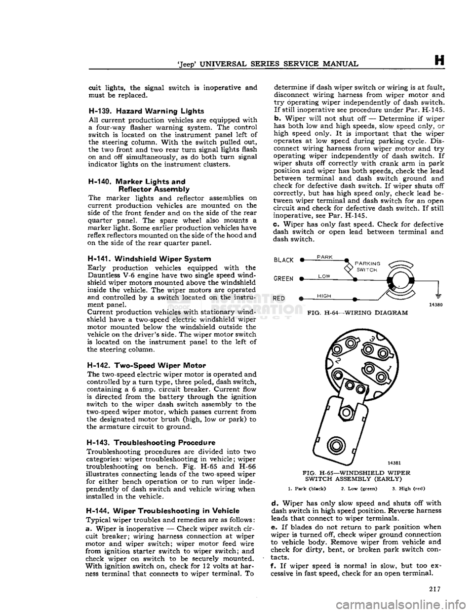
FIG.
H-64—WIRING
DIAGRAM
FIG.
H-65—WINDSHIELD
WIPER
SWITCH
ASSEMBLY
(EARLY)
1.
Park
(black)
2. Low (green)
3.
High (red)
d.
Wiper
has
only slow speed
and
shuts
off
with
dash switch in high speed position. Reverse harness
leads that connect
to
wiper terminals.
e. If
blades
do not
return
to
park
position when
wiper
is
turned
off,
check wiper ground connection
to vehicle body. Remove wiper from vehicle
and
check
for
dirty, bent,
or
broken
park
switch con
tacts.
f.
If
wiper speed
is
normal
in
slow,
but too ex
cessive
in
fast speed, check for an open terminal. 217
Page 220 of 376
H
ELECTRICAL
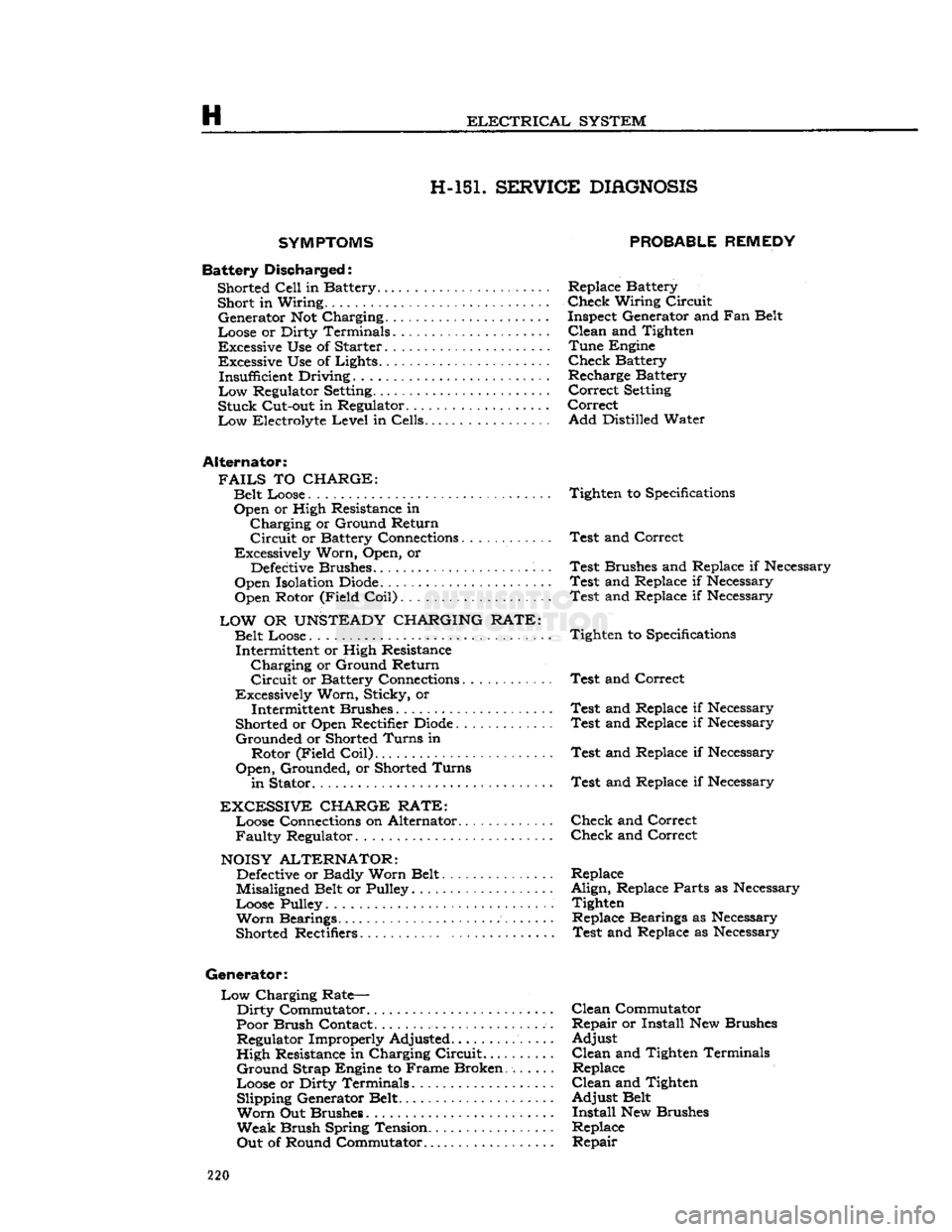
SYSTEM H-15L SERVICE
DIAGNOSIS
SYMPTOMS
Battery
Discha
rged: Shorted
Cell
in Battery......... Short in Wiring..
•
Generator Not Charging ,
Loose or Dirty Terminals
Excessive Use of Starter Excessive Use of Lights...... Insufficient Driving.........
Low
Regulator
Setting.......
Stuck
Cut-out in Regulator. ..
Low
Electrolyte
Level
in Cells
Alternator:
FAILS
TO
CHARGE:
Belt Loose Open or High Resistance in
Charging
or Ground Return
Circuit
or Battery Connections............
Excessively Worn, Open, or
Defective
Brushes.
Open Isolation
Diode.
Open Rotor (Field
Coil)
LOW
OR
UNSTEADY
CHARGING RATE:
Belt Loose.... Intermittent or High Resistance
Charging
or Ground Return
Circuit
or Battery Connections
Excessively Worn, Sticky, or Intermittent Brushes
Shorted or Open Rectifier
Diode
Grounded
or Shorted
Turns
in Rotor (Field
Coil)
Open,
Grounded, or Shorted
Turns
in
Stator
EXCESSIVE
CHARGE RATE:
Loose Connections on Alternator...........
Faulty
Regulator
NOISY
ALTERNATOR:
Defective
or Badly Worn Belt
Misaligned Belt or Pulley
Loose Pulley
Worn
Bearings.
Shorted Rectifiers
Generator:
Low
Charging Rate—
Dirty
Commutator
Poor Brush Contact.
................
Regulator Improperly Adjusted.......
High
Resistance in Charging
Circuit...
Ground
Strap Engine to Frame Broken
Loose or Dirty Terminals Slipping Generator Belt
Worn
Out Brushes
Weak
Brush Spring Tension..........
Out
of Round Commutator
PROBABLE REMEDY
Replace Battery
Check
Wiring
Circuit
Inspect Generator and Fan Belt
Clean
and Tighten
Tune
Engine
Check
Battery
Recharge Battery
Correct
Setting
Correct
Add
Distilled Water
Tighten to
Specifications
Test
and Correct
Test
Brushes and Replace if Necessary
Test
and Replace if Necessary
Test
and Replace if Necessary
Tighten to
Specifications
Test
and Correct
Test
and Replace if Necessary
Test
and Replace if Necessary
Test
and Replace if Necessary
Test
and Replace if Necessary
Check
and Correct
Check
and Correct
Replace
Align,
Replace Parts as Necessary Tighten Replace Bearings as Necessary
Test
and Replace as Necessary
Clean
Commutator
Repair
or Install New Brushes
Adjust
Clean
and Tighten Terminals Replace
Clean
and Tighten
Adjust
Belt
Install
New Brushes
Replace
Repair
220
Page 221 of 376
'Jeep*
UNIVERSAL
SERIES SERVICE
MANUAL
H
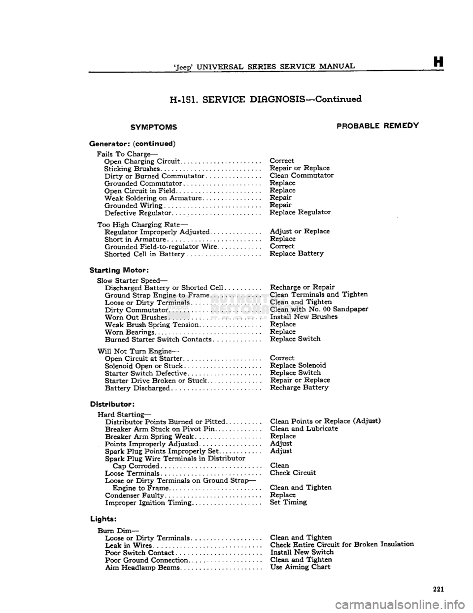
H-151.
SERVICE
DIAGNOSIS—Continued
SYMPTOMS PROBABLE
REMEDY
Generator:
(continued)
Fails
To Charge-Open Charging Circuit Correct
Sticking Brushes Repair or Replace
Dirty
or Burned Commutator ... Clean Commutator
Grounded Commutator Replace
Open Circuit in Field Replace
Weak Soldering on Armature. . . Repair Grounded Wiring Repair
Defective
Regulator. .. Replace Regulator
Too High Charging Rate— Regulator Improperly Adjusted Adjust or Replace
Short in Armature Replace Grounded Field-to-regulator Wire Correct
Shorted
Cell
in Battery... Replace Battery
Starting
Motor: Slow Starter Speed— Discharged Battery or Shorted
Cell
Recharge or Repair
Ground
Strap Engine to Frame. Clean Terminals and Tighten
Loose or Dirty Terminals Clean and Tighten
Dirty
Commutator Clean with No. 00 Sandpaper
Worn
Out Brushes Install New Brushes
Weak Brush Spring Tension Replace
Worn
Bearings Replace Burned Starter Switch Contacts Replace Switch
Will
Not
Turn
Engine— Open Circuit at Starter Correct
Solenoid
Open or Stuck Replace
Solenoid
Starter Switch
Defective
Replace Switch
Starter Drive Broken or Stuck. Repair or Replace
Battery Discharged Recharge Battery
Distributor:
Hard
Starting— Distributor
Points
Burned or Pitted Clean
Points
or Replace (Adjust)
Breaker
Arm Stuck on Pivot Pin...... . ... . . . Clean and Lubricate
Breaker
Arm Spring Weak Replace
Points
Improperly Adjusted Adjust
Spark
Plug
Points
Improperly Set Adjust
Spark
Plug Wire Terminals in Distributor
Cap
Corroded Clean
Loose Terminals Check Circuit
Loose or Dirty Terminals on Ground Strap— Engine to Frame. Clean and Tighten
Condenser Faulty Replace Improper Ignition Timing Set Timing
Lights:
Burn
Dim— Loose or Dirty Terminals....... ........ Clean and Tighten
Leak
in Wires. Check Entire Circuit for Broken Insulation
Poor Switch Contact Install New Switch Poor Ground Connection Clean and Tighten
Aim
Headlamp Beams. Use Aiming
Chart
221
Page 224 of 376
H
ELECTRICAL
SYSTEM
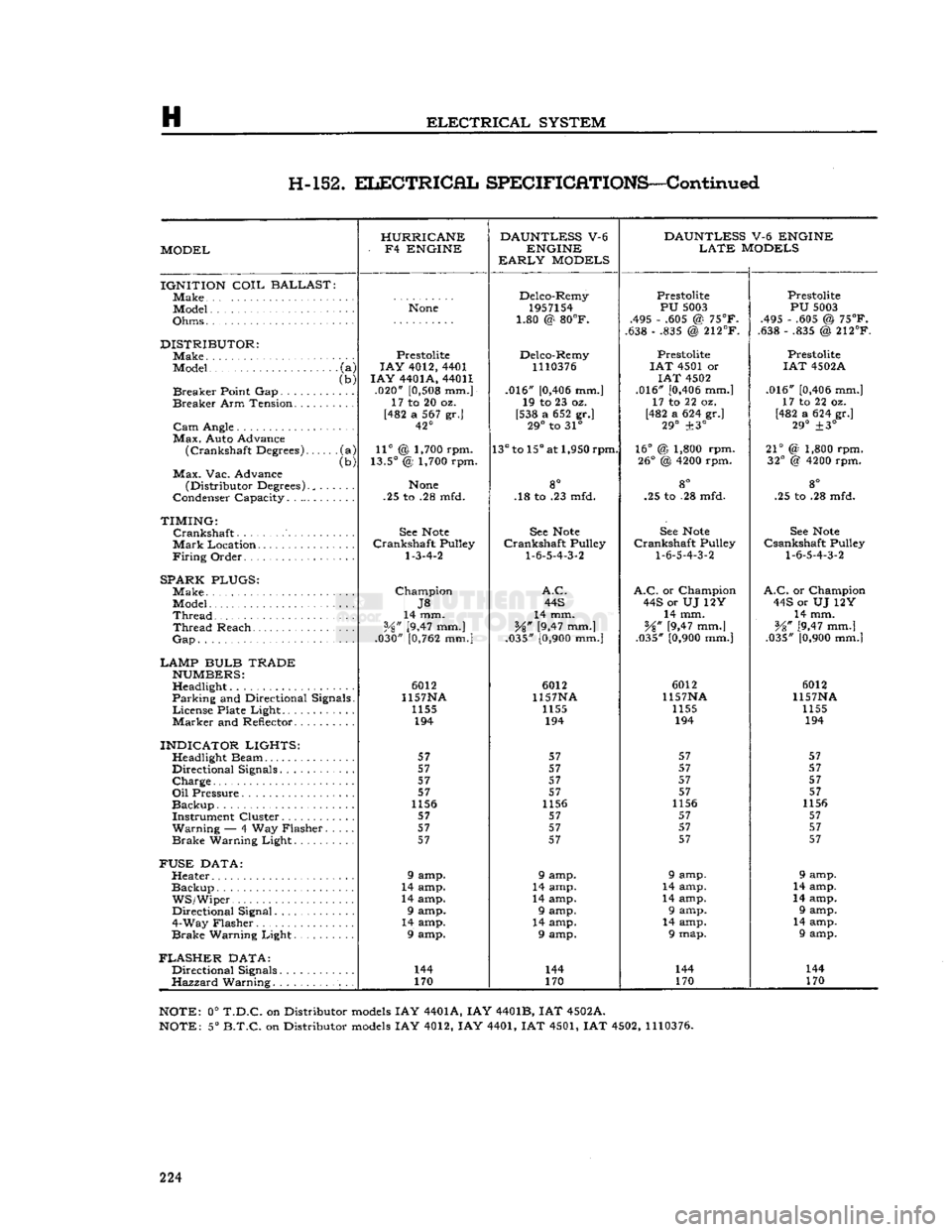
H-152.
ELECTRICAL
SPECIFICATIONS—Continued
HURRICANE DAUNTLESS
V-6
DAUNTLESS
V-6 ENGINE
MODEL -
F4
ENGINE
ENGINE
LATE
MODELS
EARLY
MODELS
IGNITION
COIL
BALLAST
]Make Delco-Remy
Prestolite Prestolite
Model
None
1957154
PU
5003
PU
5003
Ohms • • 1.80 @
80°F.
.495 - .605 @
75°F.
.495 - .605 @
75°F.
1.80 @
80°F.
.638 - .835 @
212°F.
.638 - .835 @
212°F.
DISTRIBUTOR:
Prestolite Delco-Remy Prestolite Prestolite
Model
•
(a)
LAY
4012, 4401
1110376
I
AT
4501 or
IAT
4502A
(b)
I
AY
4401A, 44011
IAT
4502
Breaker
Point Gap (b)
.020"
[0,508
mm.] .016"
[0,406
mm.] .016"
[0,406
mm.]
.016"
[0,406
mm.]
Breaker
Arm Tension. ..... 17 to 20 oz.
19 to 23 oz. 17 to 22 oz. 17 to 22 oz.
[482 a 567 gr.] [538 a 652 gr.] [482 a 624 gr.]
[482 a 624 gr.]
42° 29°
to 31°
29°
±3°
29°
±3°
Max.
Auto Advance
(Crankshaft
Degrees) •(a)
11°
@ 1,700 rpm.
13°
to
15°
at 1,950 rpm.
16°
@ 1,800 rpm.
21°
(2 1,800 rpm.
(Crankshaft
Degrees)
(b)
13.5°
@ 1,700 rpm.
26°
@
4200
rpm.
32°
@
4200
rpm.
Max.
Vac. Advance go
(Distributor Degrees)., . .
None
8° 8°
go
Condenser Capacity. . .25 to .28 mfd. .18 to .23 mfd. .25 to .28 mfd. .25 to .28 mfd.
TIMING:
Crankshaft
See
Note
See
Note
See
Note
See
Note
Mark
Location............
Crankshaft
Pulley
Crankshaft
Pulley
Crankshaft
Pulley
Csankshaft
Pulley
Firing
Order
1-3-4-2
1-6-5-4-3-2
1-6-5-4-3-2 1-6-5-4-3-2
SPARK PLUGS:
Make
Champion
A.C. A.C.
or Champion
A.C.
or Champion
J8
44S
44S or UJ 12Y 44S or UJ 12Y
Thread
14 mm.
14 mm. 14 mm. 14 mm.
Thread
Reach
Vz"
[9,47 mm.]
%"
[9,47 mm.]
¥%"
[9,47 mm.]
V8" [9,47 mm.]
Gap
.030"
[0,762
mm.]
.035"
[0,900
mm.] .035"
[0,900
mm.] .035"
[0,900
mm.|
LAMP BULB TRADE
NUMBERS:
Headlight 6012
6012 6012 6012
Parking
and Directional Signals. 1157NA
1157NA 1157NA 1157NA
License
Plate Light........ 1155
1155 1155 1155
Marker
and Reflector 194
194 194 194
INDICATOR LIGHTS:
57 57 57 57
Directional Signals........ 57
57 57 57
Charge
57
57 57 57
57 57 57 57
1156 1156 1156 1156
Instrument Cluster 57 57 57 57
Warning
— 4 Way Flasher. . 57
57 57 57
Brake
Warning Light 57
57 57 57
FUSE
DATA:
Heater 9 amp. 9 amp. 9 amp. 9 amp.
Backup
14 amp. 14 amp. 14 amp. 14 amp.
WS/Wiper.
14 amp. 14 amp. 14 amp. 14 amp.
Directional Signal 9 amp. 9 amp. 9 amp. 9 amp.
4-Way Flasher 14 amp. 14 amp. 14 amp. 14 amp.
Brake
Warning Light 9 amp. 9 amp. 9 map. 9 amp.
FLASHER
DATA:
Directional Signals. 144
144 144 144
Hazzard
Warning. 170
170 170 170
NOTE:
0°
T.D.C.
on Distributor
models
IAY 4401A, IAY 4401B, IAT 4502A.
NOTE:
5°
B.T.C.
on Distributor
models
IAY 4012, IAY 4401, IAT 4501, IAT 4502,
1110376.
224
Page 371 of 376
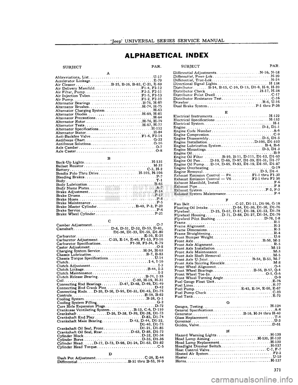
'Jeep'
UNIVERSAL
SERIES SERVICE
MANUAL
ALPHABETICAL INDEX
SUBJECT PAR.
SUBJECT
PAR.
Abbreviations,
List
U-17 Accelerator Linkage E-70
Air
Cleaner B-25, B-26, B-82, C-21, E-69
Air
Delivery Manifold Fl-4, F2-12
Air
Filter, Pump • F2-3, F2-11
Air
Injection Tubes Fl-5, F2-13
Air
Pump Fl-2, F2-10
Alternator Bearings B-76, H-80
Alternator Brushes H-74, H-75
Alternator Charging System •
•
H-63
Alternator
Diodes
H-69, H-85
Alternator Precautions H-64 Alternator Rotor H-76, H-79
Alternator Tests H-67, H-77 Alternator Specifications H-l 52
Alternator Stator H-84
Anti-Backfire
Valve Fl-6, F2-14
Antifreeze
Chart
• G-22 Antifreeze
Solutions
- G-16
Axle Camber O-l
Axle Caster 0-8
Back-Up
Lights H-135
Ballast
Resistor. H-32 Battery C-3, H-2 Bendix Folo-Thru Drive H-105, H-106
Bleeding Brakes P-7
Body T-l Body Lubrication. B-65 Body Name Plates ' A-7
Brake
Adjustment P-14
Brake
Drums. • .P-17
Brake
Hoses
P-8
Brake
Maintenance . P-5
Brake
Master Cylinder B-40, P-2, P-20
Brake
Service P-6
Brake
Wheel Cylinder • P-21
Camber
Adjustment 0-7
Camshaft D-6, D-51, D-52, D-53, D-81, Dl-26, Dl-33, Dl-55, Dl-80
Carburetor
E-10, E-25
Carburetor
Adjustment C-25, E-14, E-40,
Fl-13,
F2-16
Carburetor
Specifications .Fl-38, F2-34, E-79
Caster
Adjustment 0-8
Charging
System Service. .H-34, H-63
Chassis
Lubrication B-7, B-83
Chassis
Torque Specifications U-14
Clutch
1-4, MO
Clutch
Adjustment 1-3
Clutch
Linkage B-44, 1-3
Clutch
Maintenance .. 1-2
Clutch
Release Bearing B-74, 1-25
Coil
C-20, H-19, H-31 Connecting Rod Bearings D-47, D-48, D-49, Dl-49 Connecting Rod
Crank
Pins D-42
Connecting Rods... .D-20, D-50, D-95, Dl-31, Dl-45, Dl-75
Controls B-59, B-62
Cooling System B-28, G-l Cooling System Filling G-2
Core
Hole Expansion Plugs D-72
Crankcase
Ventilating System B-13, C-6, D-110
Crankshaft
D-26, D-38, D-39, Dl-38, Dl-73
Crankshaft
End Play. D-83, Dl-74
Crankshaft
Main Bearing D-43, D-44, Dl-32, Dl-40, Dl-73
Crankshaft
Oil Seal, Front Dl-21, Dl-85
Crankshaft
Oil Seal, Rear D-63, D-85, Dl-72
Cylinder
Block D-32, Dl-34
Cylinder
Bores D-35, Dl-36
Cylinder
Head D-17, D-73, D-98, Dl-24, Dl-63, Dl-82
Cylinder
Head Torque. C-5
Dash Pot Adjustment C-26, E-44
Differential B-51 thru B-53, N-9 Differential Adjustments N-16, N-18
Differential, Powr-Lok N-20
Differential,
Trac-Lok
N-24
Directional Signal Lights. . H-138
Distributor B-14, B-15, C-10, D-13, Dl-9, H-9, H-20 Distributor Check H-l7, H-28
Distributor Point Dwell C-17 Distributor Resistance Test C-16
Drawbar
.R-6, U-16
Dual
Brake System P-l thru P-26
Electrical
Instruments H-l22
Electrical
Specifications .H-l52
Electrical
System H-l Engine .
..D-l,
Dl-1
Engine Code Number A-6
Engine Compression .
.
C-9 Engine Disassembly . • .D-6, Dl-5 Engine Installation D-105, Dl-102
Engine Lubrication System B-4, B-6 Engine Mountings D-3, Dl-3
Engine Oil B-9
Engine Oil Filter B-10, B-ll,
D-lll,
Dl-13, Dl-93
Engine Oil Pan D-l9, D-66, D-97, Dl-29, Dl-51, Dl-77 Engine Oil Pump. . .D-14, D-65, D-93, Dl-19, Dl-50, Dl-87
Engine Overheating. G-l9 Engine Removal D-5, Dl-4.
Exhaust
Emission Control — F4 Fl-1 thru Fl-30
Exhaust
Emission Control — V6 F2-1 thru F2-36
Exhaust
Manifold, Install F-6
Exhaust
Pipe -
•
F-8
Exhaust
System F-2, F-3
Exhaust
System Maintenance F-4
Fan
Belt C-27, Dl-11, Dl-96, G-18
Floating Oil Intake. D-64, Dl-30, Dl-50, Dl-76 Flywheel D-25, D-67, D-87, Dl-28, Dl-52, Dl-78
Flywheel Housing. D-71, D-88, Dl-27, Dl-54, Dl-79
Flywheel Pilot Bushing D-70, 1-8
Frame
R-l
Frame
Alignment. R-2
Frame
Dimensions R-3
Frame
Straightening R-4
Front
Bumper Weight. • U-9
Front
Axle B-50, M-2
Front
Axle Alignment R-5
Front
Axle Installation • M-12
Front
Axle Maintenance M-3
Front
Axle Shaft Removal M-5
Front
Axle U-Joint B-54, B-55, M-7
Front
Axle Steering Knuckle M-&
Front
Wheel Alignment 0-4
Front
Wheel Bearings B-56, B-57, Q-4
Front
Wheel Toe-in 0-5, 0-6
Front
Wheel Turning Angle 0-9
Fuel
Gauge Float Unit F-76
Fuel
Lines - E-77
Fuel
Pump E-45, E-54, E-60, E-67
Fuel
Pump Check C-23
Fuel
Tank
E-72
G
Gauges, Testing H-l24
General
Specifications A-8
Generator B-16, H-34 thru H-40
Glass
Replacement • T-4
Governor. . .
•.
• U-3
Guides, Valve D"61
H
Hazard
Warning Lights H-139
Head Lamp Aiming H-131, H-132 Head Lamp Replacement H-130
Headlight Dimmer Switch H-l
2
7
Heat Control Valve C-7, F-7 Heated Air System • •
•
F2-2
Heater U-10
Horns.....
....H-137 371
Page 372 of 376
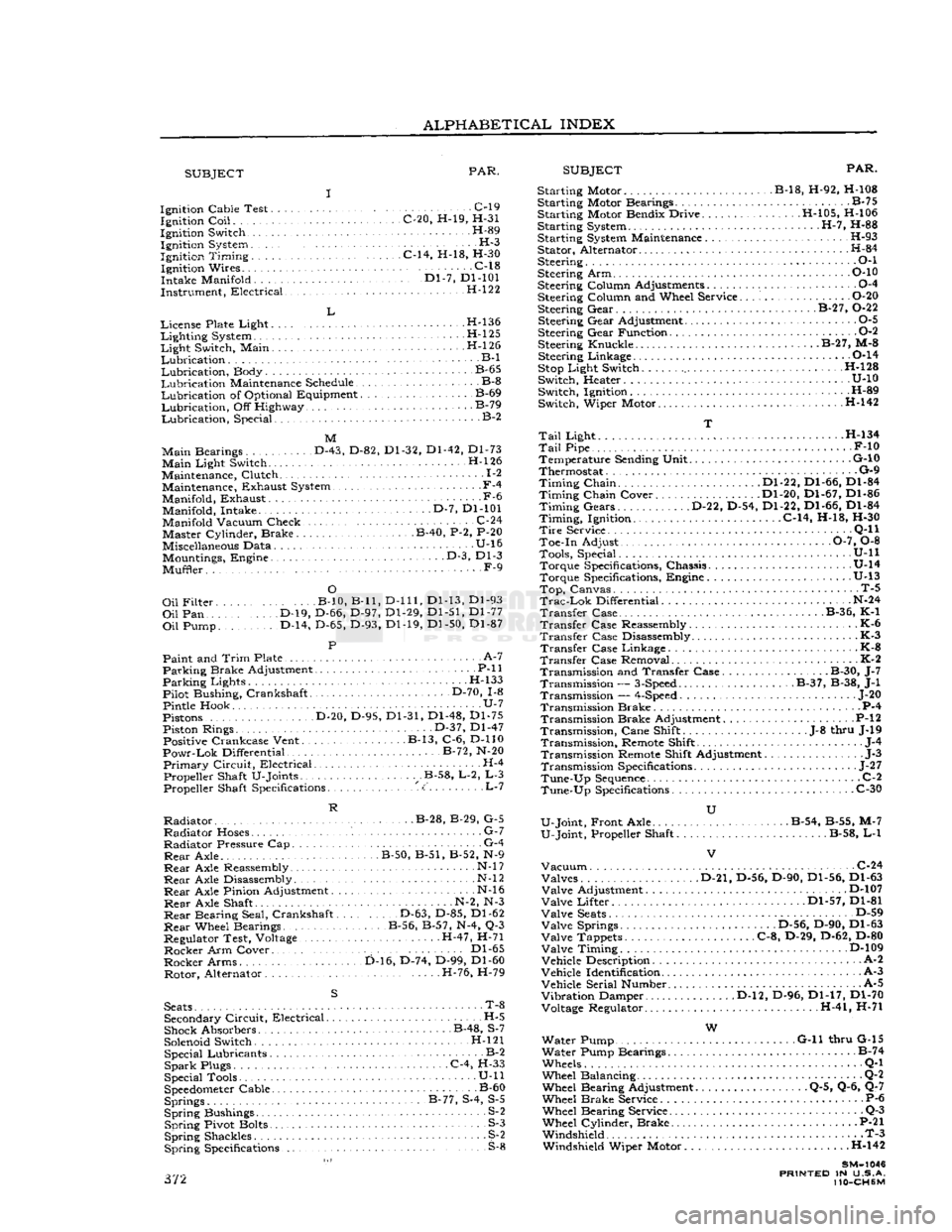
ALPHABETICAL
INDEX
SUBJECT
PAR.
SUBJECT
PAR.
Ignition Cable Test C-l9 Ignition
Coil
C-20, H-19, H-31
Ignition Switch H-89 Ignition System H-3
Ignition
Timing
C-14, H-18, H-30 Ignition Wires C-18
Intake Manifold '." Dl-7, Dl-101
Instrument, Electrical H-122
L
License Plate Light H-l36
Lighting
System H-l25
Light
Switch, Main . H-l 26
Lubrication
B-l
Lubrication,
Body B-65
Lubrication
Maintenance Schedule B-8
Lubrication
of Optional Equipment B-69
Lubrication,
Off Highway B-79
Lubrication,
Special. B-2
M
Main
Bearings D-43, D-82, Dl-32, Dl-42, Dl-73
Main
Light Switch. H-l26
Maintenance, Clutch 1-2 Maintenance, Exhaust System.,
-
F-4
Manifold, Exhaust -F-6 Manifold, Intake D-7, Dl-101
Manifold Vacuum Check. .C-24 Master Cylinder, Brake B-40, P-2, P-20
Miscellaneous Data U-16 Mountings, Engine • • •
-
D-3, Dl-3
Muffler. F-9
O
Oil
Filter B-10, B-ll,
D-lll,
Dl-13, Dl-93
Oil
Pan D-19, D-66, D-97, Dl-29, Dl-51, Dl-77
Oil
Pump. D-14, D-65, D-93, Dl-19, Dl-50, Dl-87
P
Paint and
Trim
Plate • • A-7
Parking
Brake Adjustment P-ll
Parking
Lights H-133
Pilot Bushing, Crankshaft D-70, 1-8
Pintle Hook U-7
Pistons D-20, D-95, Dl-31, Dl-48, Dl-75 Piston Rings. • • •
•
D-37, Dl-47 Positive Crankcase Vent. B-13, C-6, D-110
Powr-Lok
Differential B-72, N-20
Primary
Circuit,
Electrical H-4 Propeller Shaft U-Joints .B-58, L-2, L-3 Propeller Shaft Specifications <:' L-7
R
Radiator
B-28, B-29, G-5
Radiator
Hoses. G-7
Radiator
Pressure Cap G-4
Rear
Axle. B-50, B-51, B-52, N-9
Rear
Axle Reassembly • N-l
7
Rear
Axle Disassembly N-l
2
Rear
Axle Pinion Adjustment N-l6
Rear
Axle Shaft N-2, N-3
Rear
Bearing Seal, Crankshaft D-63, D-85, Dl-62
Rear
Wheel Bearings B-56, B-57, N-4, Q-3
Regulator Test, Voltage H-47, H-71
Rocker
Arm Cover.. . Dl-65
Rocker
Arms D-16, D-74, D-99, Dl-60 Rotor, Alternator H-76, H-79
S
Seats
• T-8 Secondary
Circuit,
Electrical H-5
Shock Absorbers B-48, S-7
Solenoid Switch. H-l21 Special Lubricants B-2
Spark
Plugs C-4, H-33
Special Tools • U-ll
Speedometer
Cable B-60 Springs B-77, S-4, S-5
Spring
Bushings S-2
Spring
Pivot Bolts S-3
Spring
Shackles S^2
Spring
Specifications S-8 372 Starting Motor B-18, H-92, H-108
Starting Motor Bearings B-75
Starting Motor Bendix Drive H-105, H-106
Starting System H-7, H-88
Starting System Maintenance H-93 Stator, Alternator H-84
Steering • • •
•
O-l
Steering Arm P-10
Steering Column Adjustments 0-4
Steering Column and Wheel Service O-20 Steering Gear. . B-27, 0-22
Steering Gear Adjustment 0-5
Steering Gear Function 0-2
Steering Knuckle. B-27, M-8 Steering Linkage 0-14
Stop
Light Switch H-128
Switch, Heater U-10 Switch, Ignition H-89
Switch, Wiper Motor H-142
T
Tail
Light . H-134
Tail
Pipe F-10 Temperature Sending Unit G-10
Thermostat G-9
Timing
Chain Dl-22, Dl-66, Dl-84
Timing
Chain Cover Dl-20, Dl-67, Dl-86
Timing
Gears D-22, D-54, Dl-22, Dl-66, Dl-84
Timing,
Ignition. C-14, H-18, H-30
Tire
Service . •
•
Q-l
1
Toe-in Adjust 0-7, 0-8 Tools, Special. . .
........
U-ll Torque Specifications, Chassis U-14
Torque Specifications, Engine .U-13
Top,
Canvas. T-5
Trac-Lok
Differential N-24
Transfer
Case B-36, K-1
Transfer
Case Reassembly K-6
Transfer
Case Disassembly K-3
Transfer
Case Linkage - K-8
Transfer
Case Removal K-2 Transmission and Transfer Case. B-30, J-7 Transmission —
3-Speed
B-37, B-38, J-l
Transmission —
4-Speed
... J-20
Transmission Brake P-4 Transmission Brake Adjustment P-l
2
Transmission,
Cane Shift .J-8 thru J-19
Transmission,
Remote Shift J-4
Transmission Remote Shift Adjustment J-3
Transmission Specifications
-
J-27
Tune-Up
Sequence
C-2
Tune-Up
Specifications C-30
U
U-Joint, Front Axle . . B-54, B-55, M-7
U-Joint, Propeller Shaft B-58, L-l
Vacuum
C-24 Valves D-21, D-56, D-90, Dl-56, Dl-63
Valve
Adjustment D-107
Valve
Lifter Dl-57, Dl-81
Valve
Seats
D-59
Valve
Springs .D-56, D-90, Dl-63
Valve
Tappets C-8, D-29, D-62, D-80
Valve
Timing D-109
Vehicle Description A-2
Vehicle Identification A-3
Vehicle Serial Number. A-5
Vibration
Damper D-l2, D-96, Dl-17, Dl-70 Voltage Regulator. H-41, H-71
W
Water Pump G-ll thru G-15
Water Pump Bearings B-74
Wheels Q-l
Wheel Balancing Q-2 Wheel Bearing Adjustment Q-5, Q-6, Q-7
Wheel Brake Service P-6 Wheel Bearing Service Q-3
Wheel Cylinder, Brake P-21 Windshield T-3 Windshield Wiper Motor . .H-142
SM-1046
PRINTED
IN U.S.A.
110-CH6M