wheel alignment JEEP CJ 1953 User Guide
[x] Cancel search | Manufacturer: JEEP, Model Year: 1953, Model line: CJ, Model: JEEP CJ 1953Pages: 376, PDF Size: 19.96 MB
Page 206 of 376
H
ELECTRICAL
SYSTEM
FIG.
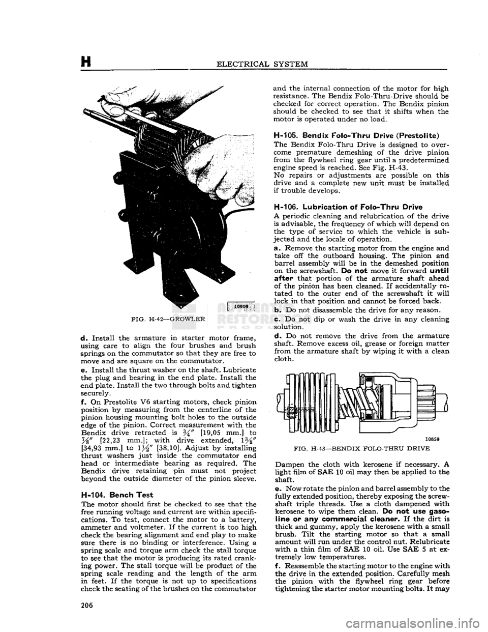
H-42—GROWLER
d.
Install
the armature in starter motor frame,
using care to align the four brushes and brush
springs on the commutator so that they are free to
move
and are square on the commutator.
e.
Install
the thrust washer on the shaft.
Lubricate
the plug and bearing in the end plate.
Install
the
end plate.
Install
the two through
bolts
and tighten securely.
f.
On Prestolite V6 starting motors, check pinion position by measuring from the centerline of the
pinion housing mounting bolt
holes
to the outside
edge
of the pinion.
Correct
measurement with the
Bendix
drive retracted is [19,05 mm.] to
%"
[22,23 mm.]; with drive extended, 1%"
[34,93
mm.] to 1^" [38,10]. Adjust by installing
thrust
washers just inside the commutator end
head or intermediate bearing as required. The
Bendix
drive retaining pin must not project
beyond the outside diameter of the pinion
sleeve.
H-104.
Bench Test
The
motor should first be checked to see that the
free running
voltage
and current are within specifi cations. To
test,
connect the motor to a battery,
ammeter and voltmeter. If the current is too high
check
the bearing alignment and end play to make
sure
there is no binding or interference. Using a
spring
scale and torque arm check the stall torque to see that the motor is producing its rated
crank
ing power. The stall torque
will
be product of the
spring
scale reading and the length of the arm
in
feet.
If the torque is not up to specifications
check
the seating of the brushes on the commutator
and
the internal connection of the motor for high
resistance. The Bendix
Folo-Thru-Drive
should be checked for correct operation. The Bendix pinion
should be checked to see that it shifts when the motor is operated under no load.
H-105.
Bendix Folo-Thru Drive (Prestolite)
The
Bendix
Folo-Thru
Drive is designed to over
come
premature demeshing of the drive pinion
from
the flywheel ring gear until a predetermined
engine
speed is reached. See Fig. H-43. No repairs or adjustments are possible on this
drive
and a
complete
new unit must be installed
if
trouble develops.
H-106.
Lubrication
of
Folo-Thru Drive
A
periodic cleaning and relubrication of the drive is advisable, the frequency of which
will
depend on
the type of service to which the vehicle is sub
jected and the locale of operation.
a.
Remove the starting motor from the
engine
and take off the outboard housing. The pinion and
barrel
assembly
will
be in the demeshed position
on the screwshaft. Do not
move
it forward
until
after
that portion of the armature shaft ahead
of the pinion has been cleaned. If accidentally ro
tated to the outer end of the screwshaft it
will
lock
in that position and cannot be forced back.
b.
Do not disassemble the drive for any reason.
c.
Do not dip or wash the drive in any cleaning solution.
d.
Do not remove the drive from the armature
shaft. Remove
excess
oil, grease or foreign matter
from
the armature shaft by wiping it with a clean cloth.
3
10859
FIG.
H-43—BENDIX
FOLO-THRU DRIVE
Dampen
the cloth with kerosene if necessary. A
light film of
SAE
10 oil may then be applied to the shaft.
e.
Now rotate the pinion and
barrel
assembly to the
fully
extended position, thereby exposing the screw shaft triple threads. Use a cloth dampened with
kerosene to wipe them clean. Do not use
gaso
line
or any
commercial cleaner.
If the dirt is
thick
and gummy, apply the kerosene with a small
brush.
Tilt
the starting motor so that a small
amount
will
run under the control nut. Relubricate
with
a thin film of
SAE
10 oil. Use SAE 5 at ex tremely low temperatures.
f.
Reassemble the starting motor to the
engine
with the drive in the extended position.
Carefully
mesh the pinion with the flywheel ring gear before
tightening the starter motor mounting bolts. It may 206
Page 239 of 376
'Jeep'
UNIVERSAL
SERIES
SERVICE
MANUAL
J
THREE-SPEED
TRANSMISSION
Contents
SUBJECT
PAR.
GENERAL
J-l
TRANSMISSION
SHIFTING
CONTROL.
. J-2
TRANSMISSION
REMOTE
CONTROL
ADJUSTMENT
J-3
REMOTE
CONTROL
DISASSEMBLY
J-4
REMOTE
CONTROL
REASSEMBLY.
. . . . J-5
TRANSMISSION
REMOVAL
J-6
SEPARATING
TRANSMISSION
AND
TRANSFER
CASE
J-7
SUBJECT
PAR.
DISASSEMBLY
OF
CANE
SHIFT
TRANSMISSION
J-8, J-12, J-16
Transmission
Cleaning and
Inspection J-10, J-18
Transmission
Interlocking Sleeve Inspection J-9
REASSEMBLY
OF
CANE
SHIFT
TRANSMISSION
J-ll,
J-14, J-19
SERVICE
DIAGNOSIS
J-20
TRANSMISSION
SPECIFICATIONS
J-21
J-1.
GENERAL
A
three speed synchromesh transmission is standard
equipment on all 'Jeep' Universal vehicles.
The
models T90 and T96 transmissions are used
with
the
Hurricane
F4 engine, and models
T86AA
and
T14A transmissions are used with the Daunt
less
V-6 engine. All model transmissions are similar
in
design with exception of the T14A which is a
fully
synchronized (all forward gears) transmission
with
helical drive gears throughout.
The
transmission assembly is attached to the
rear
face of the flywheel bell housing and is supported on a rubber insulator at the frame center cross member which forms the
rear
engine
support.
All
4-wheel-drive vehicles are equipped with a
transfer
case attached to the
rear
of the transmission.
Transfer
case service and repair procedures
are
described in Section
K.
Models
CJ-5A,
and
CJ-6A
are equipped with the
same transmission, but with a remote control shift.
Models DJ-5 and DJ-6 are equipped with a similar
transmission,
however, the construction is
some
what different because it is not designed to receive a transfer case for four-wheel drive.
For
DJ-5 and DJ-6 2WD vehicles, the trans mission repair procedures begin with Par. J-12.
J-2.
TRANSMISSION SHIFTING CONTROL
The
shift of the three-speed transmission is smooth
and
positive. The cane control lever shifts the trans
mission gears direct from the shift control housing
mounted to the top side of the transmission housing.
The
remote control lever shifts the transmission
gears through remote control rods attached to the
adjusting
levers of the shift shafts protruding from the left side of the transmission housing. Poppet
balls and springs retain the transmission gears in mesh and an interlocking mechanism prevents
shifting into two gears at the same time.
J-3.
Transmission Remote Control Adjustment
•
Early
CJ-5A,
CJ-6A
First
disconnect the transmission shift rods from the remote control levers.
Check
for binding of
the remote control shaft on the steering column
and
make the necessary corrections to eliminate any binding condition.
If
the shift is not smooth and positive, first make
sure
the gears are in neutral position then remove
the shift rods at the transmission by removing
clevis pins, Fig. J-l No. 17, and slip a short piece
of snug fitting 34" [6,35 mm.] aligning rod, through
the gearshift levers and housing as shown in insert
drawing.
This
places the clutch and shift lever assemblies
in
the neutral position. Adjust the shift rod yokes
at the transmission end, so clevis pins can be in stalled freely without moving the shift levers on the
transmission after which remove alignment pin.
If
shifting from first to second is difficult or trans
mission hangs in first gear, shorten the low and
reverse shift rod one
turn
at a time until the con
dition is corrected. Usually three turns are re
quired.
Should
the fault continue after completing the above adjustment, check further as outlined below.
First
remove the lubricating fitting. Use a narrow
feeler
gauge
which
will
enter the opening for the
lubricator
and check the clearance
between
the
faces of the shifting clutches.
This
clearance should
be .015" to .031", [W to W]
[0,397-0,794
mm.]. If
this clearance is greater the assembly must be removed for adjustment. The shift dog, which
engages
the clutch slots, should not have more than .009" [0,229 mm.] clearance in the slots. If the clear
ance
between
the clutch
grooves
and cross pins is
too great,
these
parts must be replaced.
J-4.
Removal
of
Remote Control
m
Early
CJ-5A,
CJ-6A
•
Refer to Fig. J-l
To
remove the remote control the following pro cedure is
suggested:
a.
Remove shifting rods from the transmission
and
also from the steering remote control clutch levers. 239
Page 240 of 376
THREE-SPEED
TRANSMISSION
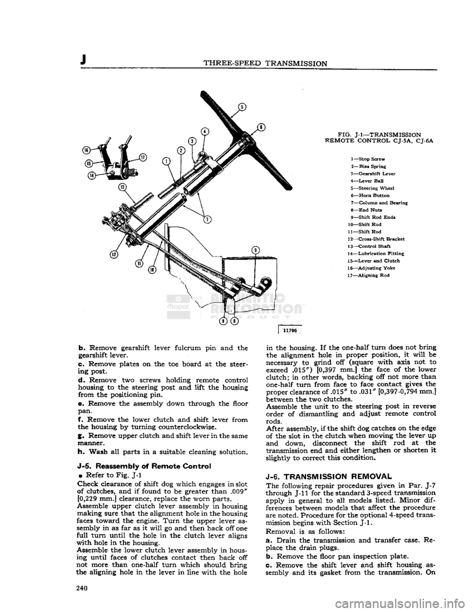
FIG.
J-l—TRANSMISSION
REMOTE
CONTROL
CJ-5
A,
CJ-6A
1— Stop Screw
2—
Bias
Spring
3—
Gearshift
Lever
4—
Lever
Ball
5—
Steering
Wheel 6—
Horn
Button 7—
Column
and Bearing
8—
End
Huts
9—
Shift
Rod
Ends
10—
Shift
Rod
11—
Shift
Rod
12—
Cross-Shift
Bracket
13—
Control
Shaft
14—
Lubrication
Fitting
15—
Lever
and
Clutch
16—
Adjusting
Yoke
17—
Aligning
Rod 11706
b.
Remove gearshift lever fulcrum pin and the
gearshift lever.
c.
Remove plates on the toe board at the steer
ing
post.
d.
Remove two screws holding remote control
housing to the steering
post
and lift the housing
from
the positioning pin.
e.
Remove the assembly down through the floor
pan.
f. Remove the lower clutch and shift lever from the housing by turning counterclockwise.
g. Remove upper clutch and shift lever in the same
manner.
h. Wash all parts in a suitable cleaning solution.
J-5.
Reassembly of
Remote
Control
•
Refer to
Fig.
J-l
Check
clearance of shift dog which
engages
in slot
of clutches, and if found to be greater than .009" [0,229 mm.] clearance, replace the worn parts.
Assemble upper clutch lever assembly in housing
making
sure that the alignment
hole
in the housing
faces toward the engine.
Turn
the upper lever as
sembly in as far as it
will
go and then back off one
full
turn
until the
hole
in the clutch lever aligns
with
hole
in the housing.
Assemble the lower clutch lever assembly in hous ing until faces of clutches contact then back off
not more than one-half
turn
which should bring
the aligning
hole
in the lever in line with the
hole
in
the housing. If the one-half
turn
does
not bring
the alignment
hole
in proper position, it
will
be
necessary to grind off (square with axis not to exceed .015") [0,397 mm.] the face of the lower
clutch;
in other words, backing off not more than
one-half
turn
from face to face contact
gives
the
proper
clearance of .015" to .031"
[0,397-0,794
mm.]
between
the two clutches.
Assemble the unit to the steering
post
in reverse
order
of dismantling and adjust remote control
rods.
After
assembly, if the shift dog catches on the
edge
of the slot in the clutch when moving the lever up
and
down, disconnect the shift rod at the
transmission
end and either lengthen or shorten it
slightly to correct this condition.
J-6.
TRANSMISSION
REMOVAL
The
following repair procedures given in Par. J-7
through J-ll for the standard
3-speed
transmission
apply
in general to all models listed. Minor dif
ferences
between
models that affect the procedure
are
noted. Procedure for the optional
4-speed
transmission
begins
with Section
J-l.
Removal
is as follows:
a.
Drain
the transmission and transfer case. Re place the
drain
plugs.
b.
Remove the floor pan inspection plate.
c.
Remove the shift lever and shift housing as sembly and its gasket from the transmission. On 240
Page 278 of 376
M
FRONT
AXLE
1— Nut
2—
Lock
Washer
3—
Bearing
Lock
Washer
4—
Wheel
Bearing Cup 5—
Cone
and Rollers
6—
Oil
Seal 7— Spindle
8— Spindle Bushing
9—
Filler
Plug
10—
Right
Knuckle and Arm
11— Shims
12— Pivot Pin
13—
Lock
Washer
14—
Cap
Screw
15— Nut
16—
Washer
17—
Universal
Joint Yoke
18—
Oil
Seal
19—
Oil
Slinger
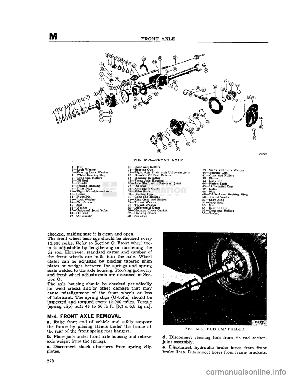
FIG.
M-2—FRONT
AXLE
20—
Cone
and Rollers
21—
Bearing
Cup
22—
Right
Axle Shaft with Universal Joint
23—
Knuckle
Oil Seal Retainer
24— Housing Breather 25—
Front
Axle Housing
26—
Axle
Shaft with Universal Joint
27—
Oil
Seal
28—
Axle
Shaft Guide
29—
Shim
Pack
30—
Bearing
Cup
31—
Cone
and Rollers
32—
Ring
Gear
and Pinion
33—
Thrust
Washer
34—
Thrust
Washer
35—
Differential
Gears
36— Housing Cover Gasket
37— Housing Cover
38—
Fill
Plug 39—
Screw
and
Lock
Washer
40—
Bearing
Cup
41—
Cone
and Rollers
42— Shims
43—
Lock
Pin
44—
Pinion
Shaft
45—
Differential
Case
47— Bolts
48— Nut
49—
Oil
Seal and Backing Ring
50—
Thrust
Washer
51— Snap Ring
52— Stop Bolt
53— Nut 54—
Bearing
Cup
55—
Cone
and Rollers
56—
Gasket
checked, making sure it is clean and open.
The
front wheel bearings should be checked every
12,000
miles. Refer to Section Q. Front wheel toe-
in
is adjustable by lengthening or shortening the
tie rod. However, standard caster and camber of
the front
wheels
are built
into
the axle. Wheel
caster can be adjusted by placing tapered shim
plates or
wedges
between
the springs and spring
seats
welded to the axle housing. Steering
geometry
and
front wheel adjustments are discussed in Sec tion O.
The
axle housing should be checked periodically
for weld cracks and/or other damage that may cause misalignment of the front
wheels
or
loss
of lubricant. The spring clips (U-bolts) should be
inspected and torqued every
12,000
miles. Torque (spring clip) nuts 45 to 50 lb-ft. [6,2 a 6,9 kg-m.].
M-4. FRONT
AXLE
REMOVAL
a.
Raise front end of vehicle
arid
safely support the frame by placing stands under the frame at
the rear of the front spring rear hangers.
b. Place
jack
under front axle housing and relieve
axle
weight
from the springs.
c. Disconnect shock absorbers from spring clip plates.
FIG.
M-3—HUB
CAP
PULLER
d.
Disconnect steering link from tie rod socket-
joint assembly.
e. Disconnect hydraulic brake
hoses
from front
brake
lines. Disconnect
hoses
from frame brackets. 278
Page 282 of 376
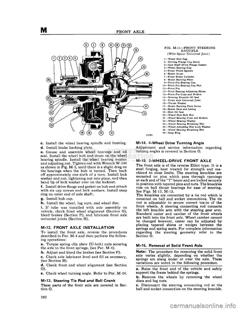
FRONT
AXLE
FIG.
M-l
1—FRONT
STEERING
KNUCKLE
(With
Spicer Universal Joint)
1—
Wheel
Hub Cap
2—
Driving
Flange Cap Screw
3—
Axle
Shaft Drive Flange Gasket 4—
Wheel
Bearing Cup
5—
Front
Wheel Spindle
6—
Brake
Drum
7—
Front
Brake
Cylinder
8—
Brake
Backing Plate
9—
Pivot
Pin Bearing Cap
10—
Pivot
Pin Bearing Cap Nut
11—
Pivot
Pin 12—
Pivot
Bearing Adjusting Shims
13—
Pivot
Pin Cone and Rollers
14—
Steering
Knuckle
Oil Seal 15—
Front
Axle Universal Joint
16—
Thrust
Washer
17—
Brake
Backing Plate Screw
18—
Brake
Shoe and
Lining
19—
Hub
Oil Seal
20—
Wheel
Hub Bolt Nut
21—
Wheel
Bearing Cone and Rollers 22—
Wheel
Bearing Washer
23—
Wheel
Bearing Retaining Nut
24—
Wheel
Adjusting Nut
Lock
Washer
25—
Wheel
Bearing Retaining Nut
26—
Snap
Ring
c.
Install
the wheel bearing spindle and bushing.
d.
Install
brake backing plate.
e.
Grease and assemble wheel bearings and oil
seal.
Install
the wheel hub and drum on the wheel
bearing
spindle.
Install
the wheel bearing washer
and
adjusting nut. Tighten nut with
Wrench
W-144
as shown in
Fig.
M-5, until there is a slight drag on the bearings when the hub is turned.
Then
back off approximately one-sixth of a
turn.
Install
lock
washer
and nut, tightening nut
into
place, and then bend lip of lock washer over on the locknut.
f.
Install
drive
flange
and gasket on hub and attach
with
six cap screws and lock washers.
Install
snap
ring
on outer end of axle shaft.
g.
Install
hub cap.
h.
Install
the wheel, lug nuts, and wheel disc.
i.
If
tube
was installed with axle assembly on
vehicle, check front wheel alignment (Section O),
bleed brakes (Section P), and lubricate front axle
universal
joints (Section B).
M-12.
FRONT
AXLE
INSTALLATION
To
install the front axle, reverse the procedures described in
Par.
M-4 and then perform the follow
ing operations:
a.
Torque spring clip plate (U-bolt) nuts securing the axle to the front springs, (see Par. M-4).
b.
Adjust and bleed the brakes (see Section P).
c.
Check
axle lubricant level and
fill
as necessary, (see Section B).
d.
Check
front end wheel alignment (see Section
O).
e.
Check
wheel turning angle. Refer to Par. M-14.
M-13.
Steering
Tie Rod and
Bell Crank
These
parts of the front axle are covered in Sec
tion O.
M-14.
4-Wheel Drive
Turning
Angle
Adjustment
and service information regarding
turning
angles
is covered in Section O.
M-15.
2-WHEEL-DRIVE
FRONT
AXLE
The
front axle is of the reverse
Elliot
type. It is a
steel forging, heat treated for strength and ma
chined
to
close
limits. The steering knuckles are
mounted on pins which pass through
openings
at each end of the
"I"
beam and are locked securely
in
position with tapered pins and nuts. The knuckles
ride
on
ball
thrust bearings for
ease
of steering. See
Figs.
M-12, M-13.
The
knuckles are connected by a tie rod which is
mounted on
ball
and socket connections. The tie
rod
is adjustable to secure correct
toe-in
of the front wheels. A steering connecting rod
connects
the
left
knuckle arm with the steering gear arm.
Standard
caster and camber of the front
wheels
are
built
into
the front axle. Wheel camber cannot
be changed however, caster can be adjusted by
placing
tapered shims or
wedges
between
the
springs and spring seats. For
complete
information
regarding
the steering
geometry
refer to the
Section O.
M-16.
Removal of Solid
Front
Axle
Note:
The procedure for removing the solid front
axle varies slightly, depending on whether the
springs are slung under or over the axle. These
variations
are
noted
in the following procedure.
a. -
Raise the front end of the vehicle and safely support the frame behind the springs.
b.
Remove the
wheels
by removing the wheel
discs and lug nuts.
c.
Disconnect the steering connecting rod at the
ball
and socket connection on the steering knuckle. 282
Page 302 of 376
N
REAR
AXLE a.
Place the transmission in neutral.
b.
Raise one wheel off the floor and place a block
in
front and at the
rear
of the
opposite
wheel.
c.
Apply a torque wrench to the axle shaft nut of
the elevated wheel.
d.
Turn
wheel with torque wrench. Disregard
breakaway
torque and observe torque required to
continuously
turn
wheel smoothly. Torque should
read
40 lb-ft [5,53 kg-m.] or more.
N-23. Powr-Lok
Differential Disassembly
/
and Reassembly
Refer
to
Figs.
N-38 and N-39.
The
procedure for overhauling disc type
Powr-Lok
differentials is as follows:
a.
Remove axle shafts following procedure de
scribed
in Par. N-2.
b.
Remove housing cover and gasket.
c.
Remove the
Powr-Lok
differential from the axle.
Do not remove the ring gear or bearing
cone
and
rollers
unless replacement is to be made.
Mark
the hearing cups so they may later be reassembled
with
the same bearing cones.
Mark
the differential
case halves for correct alignment at reassembly.
Each
pinion mate cross shaft should also be marked
so that each pin cam surface
will
match with the
same
V-ramp
in the case when reassembled.
d.
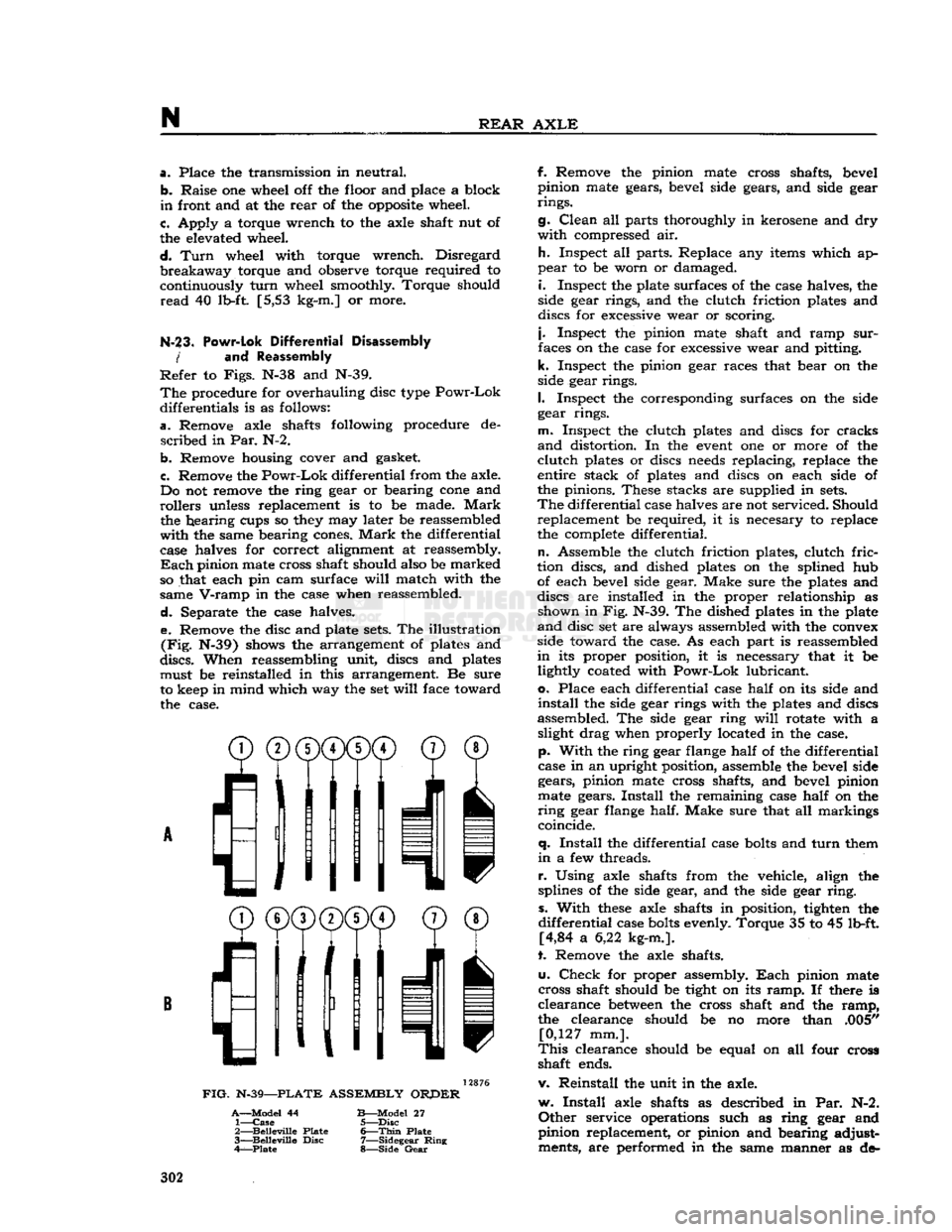
Separate the case halves. e. Remove the disc and plate
sets.
The illustration
(Fig.
N-39) shows the arrangement of plates and
discs.
When reassembling unit, discs and plates must be reinstalled in this arrangement. Be sure
to keep in mind which way the set
will
face toward the case.
^®(j)(j)CD©
® /'Ml
I
11
11 v
FIG.
N-39—PLATE
ASSEMBLY
ORPER
A—Model
44
B—Model
27 1—
Case
5—Disc
2—
Belleville
Plate
6—Thin
Plate
3—
Belleville
Disc
7—Sidegear
Ring
4—Plate
8—Side
Gear
f. Remove the pinion mate cross shafts, bevel
pinion mate gears, bevel side gears, and side gear
rings.
g.
Clean
all parts thoroughly in kerosene and dry
with
compressed air.
h.
Inspect all parts. Replace any items which ap
pear
to be worn or damaged.
i.
Inspect the plate surfaces of the case halves, the
side gear rings, and the clutch friction plates and
discs for excessive wear or scoring.
j.
Inspect the pinion mate shaft and ramp
sur
faces on the case for excessive wear and pitting,
k.
Inspect the pinion gear races that bear on the
side gear rings.
I.
Inspect the corresponding surfaces on the side
gear rings.
m.
Inspect the clutch plates and discs for cracks
and
distortion. In the
event
one or more of the
clutch
plates or discs
needs
replacing, replace the
entire stack of plates and discs on each side of
the pinions. These stacks are supplied in
sets.
The
differential case halves are not serviced. Should replacement be required, it is necesary to replace
the complete differential.
n.
Assemble the clutch friction plates, clutch
fric
tion discs, and dished plates on the splined hub of each bevel side gear. Make sure the plates and
discs are installed in the proper relationship as shown in Fig. N-39. The dished plates in the plate
and
disc set are always assembled with the convex
side toward the case. As each part is reassembled
in
its proper position, it is necessary that it be lightly coated with
Powr-Lok
lubricant,
o.
Place each differential case
half
on its side and
install
the side gear rings with the plates and discs
assembled. The side gear ring
will
rotate with a slight drag when properly located in the case,
p.
With
the ring gear flange
half
of the differential
case in an upright position, assemble the bevel side gears, pinion mate cross shafts, and bevel pinion
mate gears.
Install
the remaining case
half
on the
ring
gear flange half. Make sure that all markings
coincide.
q.
Install
the differential case
bolts
and
turn
them
in
a few threads.
r.
Using axle shafts from the vehicle, align the
splines of the side gear, and the side gear
ring,
s.
With
these
axle shafts in position, tighten the
differential
case
bolts
evenly. Torque 35 to 45 lb-ft. [4,84 a 6,22 kg-m.].
t. Remove the axle shafts.
u.
Check
for proper assembly.
Each
pinion mate
cross shaft should be tight on its
ramp.
If there is
clearance
between
the cross shaft and the
ramp,
the clearance should be no more than .005" [0,127 mm.].
This
clearance should be equal on all four cross
shaft ends.
v. Reinstall the unit in the axle.
w.
Install
axle shafts as described in Par. N-2.
Other
service operations such as ring gear and
pinion replacement, or pinion and bearing adjust ments, are performed in the same manner as de- 302
Page 313 of 376
'Jeep'
UNIVERSAL
SERIES SERVICE
MANUAL
STEERING SYSTEM
Contents
SUBJECT
PAR.
GENERAL......
O-l
Camber
Adjustment 0-9
Caster
Adjustment. .0-10
Front
Wheel Alignment Adjustments.....
.
0-6
Front
Wheel Shimmy 0-13
Front
Wheel Turning Angle Oil
Steering Knuckle Arm O-l2
Steering
Gear
Function 0-2
Steering Linkage 0-3
Toe-in
Adjustment 0-7, 8
STEERING LINKAGE SERVICE..
O-l4
Drag
Link
or Connecting Rod O-l5
Tie
Rod 0-16
Tie
Rod Removal.. O-l7
Beilcrank
Service O-l8
SUBJECT
PAR.
STEERING GEAR SERVICE
.0-22 Reassembly of Steering
Gear
0-25 Disassembly of Steering
Gear
0-24 Installation of Steering
Gear
0-26
Removal
of Steering
Gear
0-23
Steering
Gear
Adjustment. . 0-5
STEERING
COLUMN
AND
WHEEL SERVICE.
..................
.0-20
Steering Column Adjustments 0-4
Steering Wheel Installation 0-27
Steering Wheel Removal 0-21
SERVICE
DIAGNOSIS.
. 0-28
SPECIFICATIONS.
.0-29
<§>-
i©1
CJ-3B
0
0 0
®
1—
Frame
Cross Tube
(CJ-3B)
2— Steering Beilcrank Bracket
(CJ-3B)
3—
Steering Beilcrank
4—
Front
Axle Assembly 5— Steering Connecting Rod (Drag
Link)
6— Steering
Gear
Arm
7—
Steering
Gear
8—
Left
Steering Knuckle and Arm
9—
Left
Shaft and Universal Joint
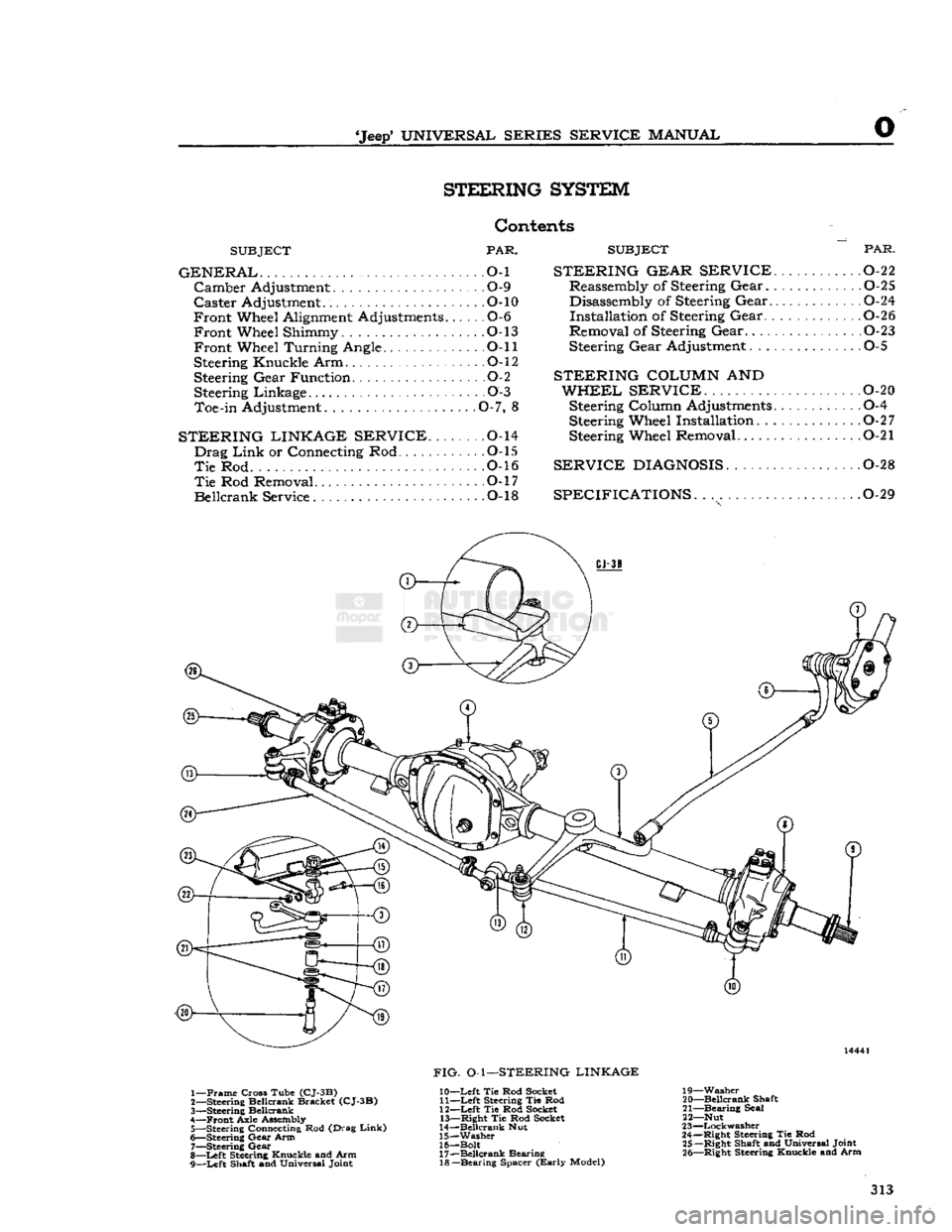
FIG.
O-l—STEERING LINKAGE
10—
Left
Tie Rod Socket 11—
Left
Steering Tie Rod
12—
Left
Tie Rod Socket 13—
Right
Tie Rod Socket
14—
Beilcrank
Nut
15—
Washer
16— Bolt 17—
Beilcrank
Bearing 18—
Bearing
Spacer
(Early
Model) 19—
Washer
20—
Beilcrank
Shaft
21—
Bearing
Seal
22— Nut
23—
Lockwasher
24—
Right
Steering Tie Rod 25—
Right
Shaft and Universal Joint 26—
Right
Steering Knuckle and Arm 313
Page 314 of 376
STEERING
SYSTEM
O-L
GENERAL
The
steering system on all Jeep Universal vehicles
consists of the steering gear, steering wheel, steering column and shaft, and steering linkage.
This
section covers wheel alignment, steering linkage,
steering gear, steering column and steering wheel.
0-2. Steering
Gear
Function
The
steering gear is a reducing gear. It exchanges a
relatively
large amount of movement with a small force (applied by the driver at the steering wheel), for a much smaller amount of movement with a
greatly increased force through a cam and lever
action type steering gear. The steering gear ratio is 17.9 to 1 on vehicles equipped with the F4
engine
and
19 to 1 with the V6 engine.
0-3. Steering
Linkage
Refer
to Fig. O-l.
The
steering linkage consists of a steering arm at
tached to the steering gear, a steering connecting
rod,
(drag
link),
connecting the steering arm to the
beilcrank,
and a steering tie rod connecting the
beilcrank
to the axle tie rod. The beilcrank pivots
on a pin mounted just to the left of the frame front crossmember. The steering tie rod is connected to
the beilcrank and
extends
to the right
ball
joint as sembly of tie rod. The tie rod
extends
to the wheels,
being connected to their respective steering knuckle
arms
at the wheels.
With
this linkage arrangement,
as the steering arm
moves
rearward,
the front
wheels
turn
to the left. As the steering arm
moves
forward,
the wheels
turn
to the right.
Ball
joints are used to secure the drag
link,
steering
connecting rod and tie rod ends. The
ball
joints
assist in maintaining
good
steering control and con
stant toe-in of the front wheels under all driving conditions. If the
ball
joints
become
worn enough
to allow free motion in the linkage, they should be,
replaced.
Note:
Ball
joint replacement of the tie rod requires
resetting of the wheel toe-in adjustment.
0-4.
Steering
Column
and Gear
Alignment
When
adjusting a steering gear remove all loads
from
the unit by disconnecting the steering con
necting rod (drag
link)
from the steering arm and
also
loosen
the instrument panel bracket and the
steering gear to frame
bolts
to allow the steering
post
to correctly align itself. When retightening the
steering gear to frame
bolts
use a torque wrench
pull
of 45 to 55 lb-ft. [6,2 a 7,6 kg-m.] on the
Vk*
bolts
and 30 to 40 lb-ft. [4,15 a 5,5 kg-m.] on the
Vs"
bolts. 10811
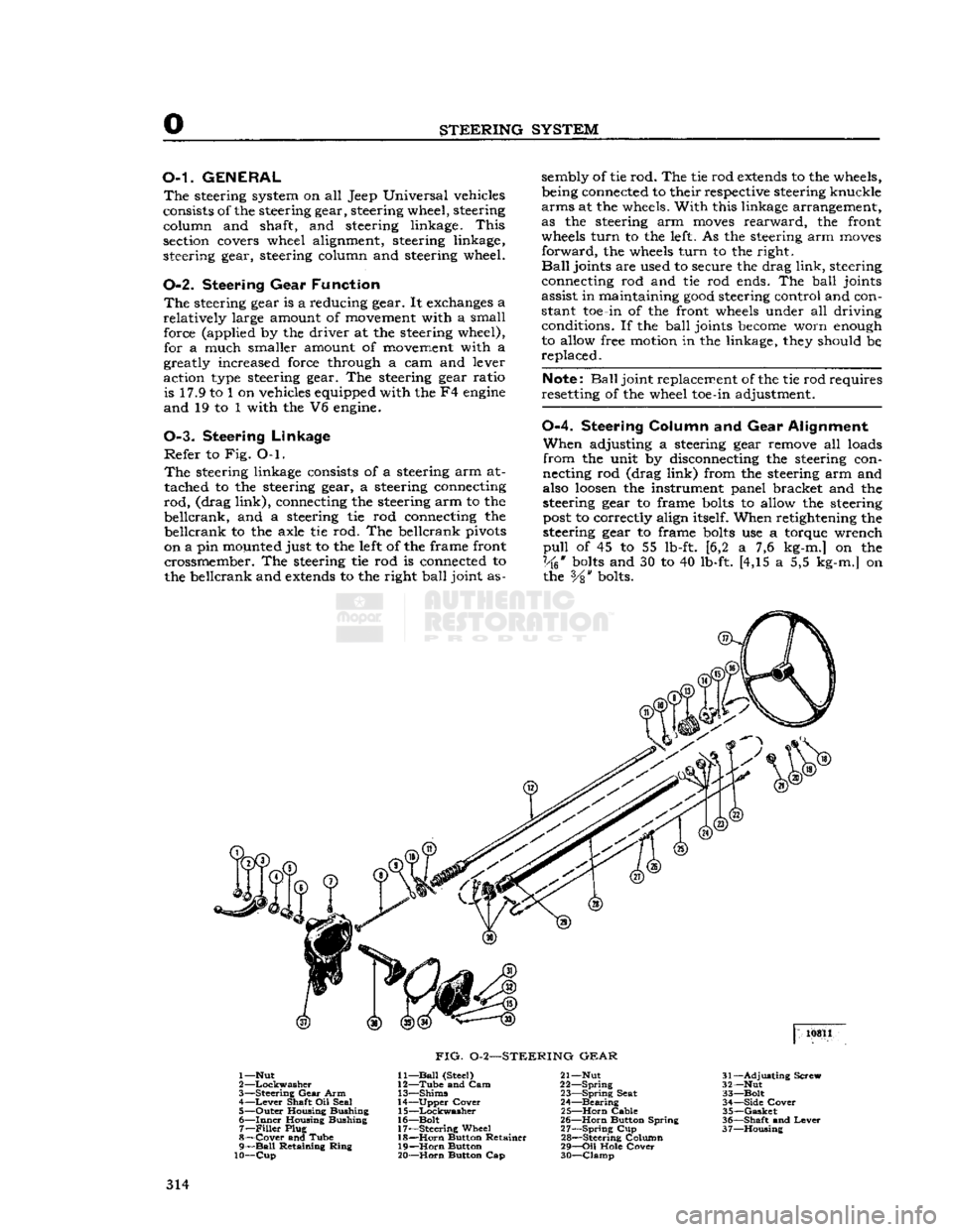
FIG.
0-2—STEERING
GEAR
1—Nut
2
—Lockwasher
3—
Steering
Gear
Arm 4—
Lever
Shaft Oil Seal
5—
Outer
Housing Bushing
6—
Inner
Housing Bushing 7—
Filler
Plug
8—
Cover
and Tube
9—
Ball
Retaining
Ring
10—Cup
11—
Ball
(Steel)
12—
Tube
and Cam
13—
Shims
14—
Upper
Cover
15—
Lockwasher
16—
Bolt
17—
Steering
Wheel 18—
Horn
Button Retainer
19—
Horn
Button
20—
Horn
Button Cap 21— Nut
22—
Spring
23—
Spring
Seat
24—
Bearing
25—
Horn
Cable
26—
Horn
Button Spring
27—
Spring
Cup
28—
Steering Column
29—
Oil
Hole
Cover
30—
Clamp
31—
Adjusting
Screw
32— Nut
33—
Bolt
34—
Side
Cover
35—
Gasket
36—
Shaft
and
Lever
37—
Housing
314
Page 315 of 376
'Jeep'
UNIVERSAL
SERIES SERVICE
MANUAL
O Note:
If the steering-gear-to-frame
bolts
are not
properly
torqued, they
will
eventually
loosen
dur
ing operation of the vehicle. Loose
bolts
will
result
in
elongated
bolt
holes
making maintenance of bolt torque difficult, and may allow position of the
steering columns to be misaligned. Therefore,
proper
torquing is extremely important.
Do not tighten the steering gear to dampen out
steering trouble. Adjust the steering gear only to
remove lost motion or play within the unit.
0-5. Steering
Gear
Adjustment
The
cam and lever steering gear is illustrated in
Fig.
0-2. It consists of a
spiral
cam, and a cross shaft and lever assembly with two lever studs.
When
the steering wheel is turned, the cam
moves
the studs, causing rotary movement of the cross
shaft, which in
turn
causes angular movement of
the*steering arm.
Two
adjustments of the steering gear are necessary:
up and down play of the steering shaft, and adjustment of the lever studs (tapered pins) in the
cam
groove.
Adjustment
of the
ball
thrust bearings to eliminate up and down play of the steering shaft is ac
complished by removing shims which are installed
between
the steering gear housing and the upper
cover. Before making this adjustment
loosen
the
housing side cover adjusting screw to free the pins
in
the cam groove. Loosen the housing cover to
cut and remove a shim or more as required.
Install
the screws and tighten. Adjustment should be
made to have a slight drag but allow the steering
wheel to
turn
freely with thumb and forefinger
lightly gripping the rim.
Shims
installed for adjustment are .002*, .003", and .010"
[.0508,
.0762
and .254 mm.] in thickness.
Adjustment
of the tapered pins in the cam
groove
is accomplished by adjusting screw. Unlock the
adjusting
screw and
turn
it in until a very slight
drag
is felt through the mid-position when turning
the steering wheel slowly from one extreme position
to the other.
Backlash
of the pins in the
groove
shows up as
end play of lever shaft, also as backlash of steer ing arm.
The
cam
groove
is purposely cut shallow in the
straight
ahead driving position for each pin.
This
feature permits a
close
adjustment for normal
straight
ahead driving and provides precision steer ing and permits take up of backlash at this point
after the wear occurs without causing a bind else
where.
Always
adjust within the high range through
the mid-position of pin travel. Do not adjust off
"straight
ahead" position.
Backlash
in turned posi
tions is not objectionable.
0-6.
Front
Wheel Alignment Adjustments
To
ensure correct alignment, a definite procedure
for inspection of the steering system is recom mended. It is
suggested
that the following sequence
be used:
a.
Equalize
tire pressures and level vehicle.
b.
Check
steering gear to steering column align
ment.
c.
Inspect steering knuckle pivots, spindle, and
wheel bearing
looseness.
d.
Check
wheel runout.
e.
Test wheel balance and bearing adjustment.
f.
Check
for spring sag.
g.
Inspect brakes and shock absorbers.
h.
Check
steering gear assembly adjustment and
steering connecting rod.
i.
Check
caster,
j.
Check
toe-in.
k.
Check
toe-out
on turns.
I.
Check
camber.
m.
Check
tracking of front and
rear
wheels,
n.
Check
frame alignment.
The
factors of alignment, caster, camber, and toe-
in,
are all interrelated and if one adjustment is
made, another adjustment may be affected.
There
fore, after an alignment job is completed, make a
complete recheck of all the adjustments to be sure
the
settings
are within the limit. Be sure all front
suspension and steering system nuts and
bolts
are
all
properly torqued before taking wheel alignment readings.
Proper
alignment of front wheels must be main
tained in order to ensure
ease
of steering and satisfactory tire life.
The
most important factors of front wheel alignment are wheel camber, axle caster and wheel
toe-in.
Wheel
toe-in is the distance the wheels are closer
together
at the front than at the
rear.
Wheel
camber is the amount the wheels incline out
ward
at the top from a vertical position.
Front
axle caster is the amount in
degrees
that the
steering pivot pins are tilted towards the front or
rear
of the vehicle. Positive caster is inclination of
the top of the pivot pin towards the
rear
of the ve
hicle.
Zero caster is the vertical position of the
pivot pin. Negative or reverse caster is the in
clination
of the top of the pin towards the front
of the vehicle.
These
points should be checked at regular inter
vals,
particularly when the front axle has been
subjected to a heavy impact. When checking wheel alignment, it is important that wheel bearings and
knuckle
bearings be in proper adjustment. Loose bearings
will
affect instrument readings when
checking
the camber, pivot pin inclination and
toe-in.
To
accurately check camber and caster, use a wheel
aligning fixture.
Camber
and caster of the front
wheels are both preset.
Camber
cannot be altered
but caster can be adjusted by installing caster shims
between
the axle pad and the springs. Wheel toe-in
may
be adjusted. To measure wheel toe-in, use a
wheel aligning fixture or follow the procedure given
in Par.
0-8.
0-7.
Front Wheel Toe-in
Toe-in
as illustrated in
Fig.
0-3, is necessary to
off
set the
effect
of camber as shown in Fig. Q-4. 315
Page 318 of 376
o
STEERING
SYSTEM
10
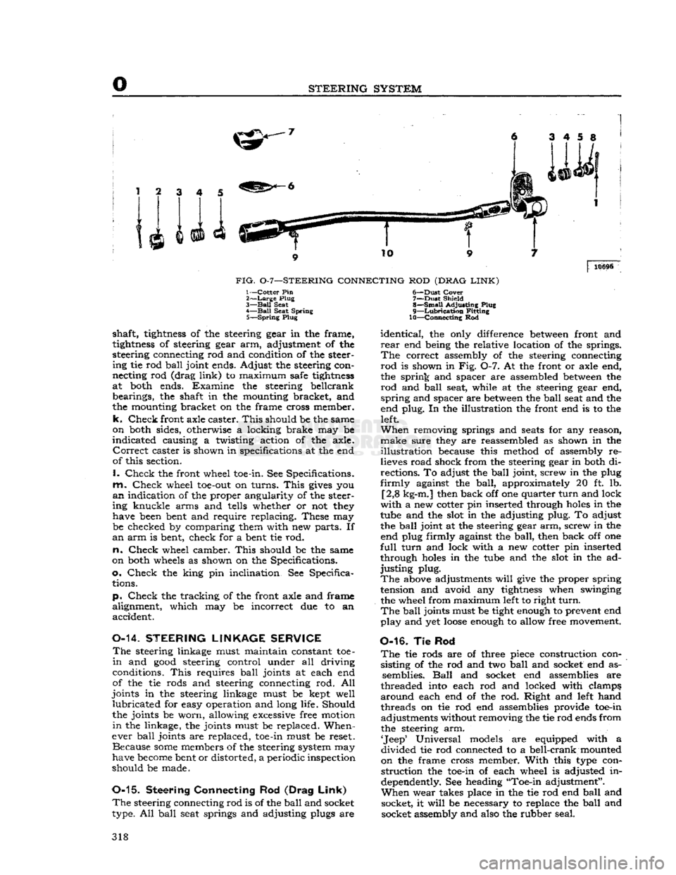
FIG.
0-7—STEERING
CONNECTING
ROD
(DRAG
LINK)
10696
1—Cotter Pin
2>—Large
Plug
3—
Ball
Seat
4—
Ball
Seat Spring 5—
Spring
Plug
shaft,
tightness
of the steering gear in the frame,
tightness
of steering gear arm, adjustment of the
steering connecting rod and condition of the steer ing tie rod
ball
joint ends. Adjust the steering con
necting rod (drag
link)
to maximum safe
tightness
at both ends. Examine the steering beilcrank bearings, the shaft in the mounting bracket, and
the mounting bracket on the frame cross member,
k.
Check
front axle caster.
This
should be the same
on both sides, otherwise a locking brake may be
indicated
causing a twisting action of the axle.
Correct
caster is shown in specifications at the end
of this section.
I.
Check
the front wheel toe-in. See Specifications,
m.
Check
wheel
toe-out
on turns.
This
gives
you
an
indication of the proper angularity of the steer
ing knuckle arms and tells whether or not they have been bent and require replacing. These may be checked by comparing them with new parts. If
an
arm is bent, check for a bent tie rod.
n.
Check
wheel camber.
This
should be the same
on both wheels as shown on the Specifications,
o.
Check
the king pin inclination. See Specifica tions.
p.
Check
the tracking of the front axle and frame
alignment, which may be incorrect due to an accident.
0-14.
STEERING
LINKAGE
SERVICE
The
steering linkage must maintain constant toe-
in
and
good
steering control under all driving
conditions.
This
requires
ball
joints at each end
of the tie rods and steering connecting rod. All
joints in the steering linkage must be kept well
lubricated
for easy operation and long life. Should
the joints be worn, allowing excessive free motion
in
the linkage, the joints must be replaced. When
ever
ball
joints are replaced, toe-in must be reset. Because
some
members of the steering system may
have
become
bent or distorted, a periodic inspection
should be made.
0-15.
Steering Connecting
Rod
(Drag
Link)
The
steering connecting rod is of the
ball
and socket
type. All
ball
seat springs and adjusting plugs are 6—
-Dust
Cover
7—
Dust
Shield
8—
Small
Adjusting Plug
9—
Lubrication
Fitting
10—Connecting Rod
identical,
the only difference
between
front and
rear
end being the relative location of the springs.
The
correct assembly of the steering connecting
rod
is shown in Fig. 0-7. At the front or axle end,
the spring and spacer are assembled
between
the
rod
and
ball
seat, while at the steering gear end,
spring
and spacer are
between
the
ball
seat and the
end plug. In the illustration the front end is to the left.
When
removing springs and
seats
for any reason,
make
sure they are reassembled as shown in the
illustration
because this method of assembly re
lieves road shock from the steering gear in both di
rections. To adjust the
ball
joint, screw in the plug
firmly
against the
ball,
approximately 20 ft. lb. [2,8 kg-m.] then back off one quarter
turn
and lock
with
a new cotter pin inserted through
holes
in the
tube and the slot in the adjusting plug. To adjust the
ball
joint at the steering gear arm, screw in the end plug firmly against the
ball,
then back off one
full
turn
and lock with a new cotter pin inserted
through
holes
in the tube and the slot in the ad
justing
plug.
The
above adjustments
will
give
the proper spring
tension and avoid any
tightness
when swinging
the wheel from maximum left to right
turn.
The
ball
joints must be tight enough to prevent end
play
and yet
loose
enough to allow free movement.
0-16. Tie Rod
The
tie rods are of three piece construction consisting of the rod and two
ball
and socket end as semblies.
Ball
and socket end assemblies are
threaded into each rod and locked with clamps,
around
each end of the rod. Right and left hand threads on tie rod end assemblies provide toe-in adjustments without removing the tie rod ends from
the steering arm.
'Jeep'
Universal models are equipped with a
divided
tie rod connected to a bell-crank mounted
on the frame cross member.
With
this type con
struction
the toe-in of each wheel is adjusted in
dependently. See heading "Toe-in adjustment".
When
wear takes place in the tie rod end
ball
and socket, it
will
be necessary to replace the
ball
and socket assembly and also the rubber seal. 318