Electrical JEEP CJ 1953 Owner's Guide
[x] Cancel search | Manufacturer: JEEP, Model Year: 1953, Model line: CJ, Model: JEEP CJ 1953Pages: 376, PDF Size: 19.96 MB
Page 201 of 376
'Jeep*
UNIVERSAL
SERIES
SERVICE
MANUAL
H
Resistance
should be approximately 0.1 ohm.
An
extremely accurate instrument would be neces
sary
to ascertain shorted turns.
Only
an open condi
tion can be detected with a commercial ohmmeter.
If
the alternator has been disassembled because of
an
electrical malfunction, replace stator only after
all
components have been checked and found to
be satisfactory.
H-85.
Out-Of-Circuit
Rectifier Diode Test
With
the rectifier diode heat sinks disconnected
from
the stator assembly (Par. H-80), the diodes
can
be individually checked with the Diode Tester
C-3829.
FIG.
H-36—RECTIFIER
DIODE
TEST
POINTS
1— Diode Plate Stud
2—
Diode Terminals
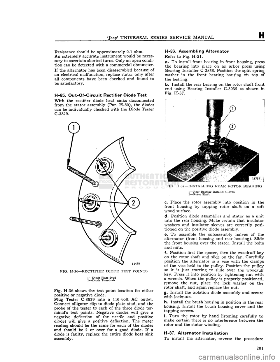
Fig.
H-36 shows the
test
point location for either positive or negative diode.
Plug
Tester C-3829 into a 110-volt AC outlet.
Connect
alligator clip to diode plate stud, and the probe of the tester to each of the three diode ter
minal's
test
points. Negative diodes
will
give a
negative deflection of the needle and positive
diodes
will
give a positive deflection. The meter
reading
should be the same for each of the diodes
and
should be 2 or over for a
good
diode. If a diode is faulty, replace the entire diode heat sink
assembly. H-86.
Assembling Alternator
Refer
to Fig. H-31.
a.
To install front bearing in front housing, press
the bearing into place on an arbor press using
Bearing
Installer C-3858. Position the split spring
washer
in the front bearing housing oh top of the bearing.
b.
Install
the
rear
bearing on the rotor shaft front
end using Bearing Installer C-3935 as shown in
Fig.
H-37.
FIG.
H-37—INSTALLING
REAR
ROTOR
BEARING
1—
Rear
Bearing Installer C-3935
2—
Rotor
Shaft
C.
Place the rotor assembly
into
position in the
front housing by tapping rotor shaft on a
soft
wood surface.
d.
Position diode assemblies and stator as a unit
into the
rear
housing. Make certain that insulator
washers and insulator
sleeves
are correctly posi
tioned on the positive diode assembly.
e.
To assemble the subassembly halves of the
alternator
(front
housing and
rear
housing). Slide
the front housing over the stator.
Install
the bolts
and
nuts.
f. Position first the spacer, then the woodruff key
on the rotor shaft and slide on the fan.
Carefully
position the alternator in a vise with the clamps
of the vise held to the pulley. Position the pulley
so it is just starting to slide over the woodruff
key.
Press it into position by tightening nut with
a
wrench. When the pulley is properly positioned,
remove the nut, place the lock washer on the
rotor
shaft, and again replace the nut.
g.
Install
the isolation diode assembly and secure
with
locknuts.
h.
Install
the brush housing in position in the
rear
housing.
Install
the brush housing cover and the
tapping screws.
i.
Turn
the rotor by hand listening carefully to
make
certain there is no interference between the
rotor
and the stator winding.
H-87.
Alternator Installation
To
install the alternator, reverse the procedure 201
Page 202 of 376
H
ELECTRICAL
SYSTEM
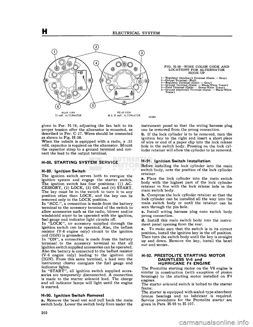
FIG.
H-38—WIRE
COLOR CODE
AND
LOCATIONS
FOR
ALTERNATOR HOOK-UP
1— Regulator (Auxiliary)
Terminal
(Cable —
Grey)
2— Output
Terminal:
(Red)
3—
Regulator
Terminal
(Cable —
Grey)
4—
Ground
Terminal
(Cable — Black-White
Tracer)
5—
Field
Terminal
(Cable — Green-White
Tracer)
6—
Ground
(Optional)
Terminal
(Cable — Black-White
Tracer)
REAR
VIEW
35
AMP.
ALTERNATOR
REAR
VIEW
40
& 55 AMP.
ALTERNATOR
given in Par. H-78, adjusting the fan belt to its
proper tension after the alternator is mounted, as described in Par. C-27. Wires should be connected
as shown in Fig. H-38.
When
the vehicle is equipped with a radio, a .55
mfd. capacitor is required on the alternator. Mount
the capacitor strap to a ground terminal and con
nect the lead to the output terminal.
H-88.
STARTING
SYSTEM
SERVICE
H-89.
Ignition
Switch
The
ignition switch serves both to energize the
ignition system and
engage
the starter switch.
The
ignition switch has four positions: (1) AC
CESSORY,
(2)
LOCK,
(3) ON, and (4)
START. The
key must be in the switch to turn it to any position other than
LOCK,
and the key can be
removed only in the
LOCK
position.
In "ACC",
a connection is made from the battery
terminal
to the accessory terminal of the switch to
allow accessories such as the radio, blower and/or
windshield wiper to be operated with the ignition, fuel
gauge
and indicator light circuits off.
In "LOCK",
no accessory supplied through the
ignition switch can be operated. Also, the ballast
resistor (V-6
engine
only) circuit to the ignition
coil
(IGN) is grounded.
In
"ON", a connection is made from the battery
terminal
to the accessory terminal so that all
ignition switch supplied accessories can be operated. Also the battery is connected to the ballast resistor
(V-6
engine
only) leading to the ignition coil
(IGN).
From
this same terminal, a lead
into
the
instrument cluster energizes the fuel
gauge
and
indicator lights.
In "START",
all ignition switch supplied acces
sories are temporarily disconnected. A connection is made to the starter solenoid lead. The charge
and
oil indicator lamps
will
light until the
engine
is started.
H-90.
Ignition
Switch
Removal
a.
Remove the bezel nut and pull back the main
switch body.
Lower
the switch
body
from under the instrument panel so that the wiring harness plug
can
be removed from the prong connection,
b. If the lock cylinder is to be removed, turn the
ignition key to the right and insert a short
piece
of wire or end of a paper clip
into
the lock release
hole
in the switch body. Pressing on the lock
cyl
inder retainer
will
allow the cylinder to be removed.
H-91.
Ignition
Switch
Installation
Before installing the lock cylinder
into
the main
switch body,
note
the position of the lock cylinder
retainer.
a.
Place the lock cylinder
into
the main switch
body
with the highest part of the lock cylinder
retainer in line with the lock release
hole
in the
main
switch body.
b. Compress the lock cylinder retainer so that the
lock cylinder can be installed all the way
into
the
main
switch
body
or until the retainer can be
seen
through the pin hole.
c.
Install
wiring harness plug
onto
switch
body
prong connection.
d.
Install
this main switch
body
into
the instru
ment panel opening from the
rear.
e. To make sure that the switch is in its correct position, install the ignition key in the off position.
Then
turn the switch
body
until the key is straight
up and down. Remove the key, install the bezel
nut and secure.
H-92.
PRESTOLITE
STARTING
MOTOR
DAUNTLESS
V-6 and
HURRICANE
F4
ENGINE
The
Prestolite starting motor on the V6
engine
is
similar
in construction (with exception of pinion housings) to the starting motor installed on F4
engines.
The
starter solenoid switch is bolted to the starter
frame.
The
starter is equipped with
sealed-type
absorbent
bronze bearings and no lubricant is required. Service procedures for the Prestolite starter are
given in
Pars.
H-93 to H-107. 202
Page 204 of 376
H
ELECTRICAL
SYSTEM
11035
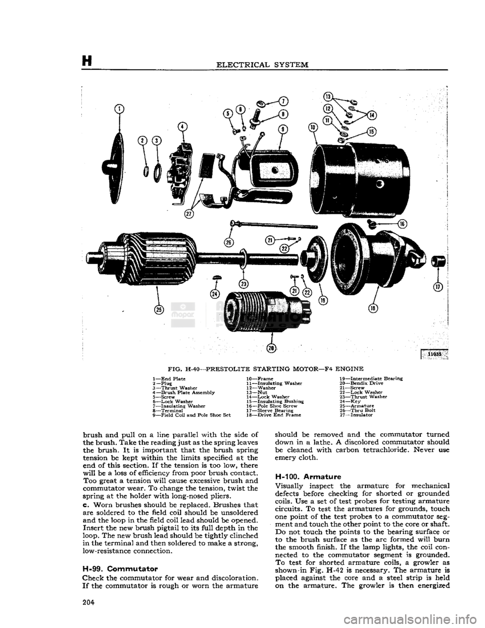
FIG.
H-40—PRESTOLITE STARTING MOTOR—F4 ENGINE 1— End
Plate
2—
Plug
3—
Thrust
Washer
4—
Brush
Plate Assembly 5— Screw
6—
—Lock
Washer
7—
Insulating
Washer
8—
Terminal
9—
Field
Coil
and Pole
Shoe
Set
10—
Frame
11—
Insulating
Washer
12—
Washer
13— Nut 14—
Lock
Washer
15—
Insulating
Bushing
16—
Pole
Shoe
Screw
17— Sleeve Bearing
18—
Drive
End Frame
19—
Intermediate Bearing
20—
Bendix
Drive
21—
Screw
22—
Lock
Washer
23—
Thrust
Washer
24— Key
25—
Armature
26—
Thru
Bolt
27—
Insulator
brush
and
pull
On
a line parallel with the side of
the
brush.
Take
the
reading
just as the spring leaves the
brush.
It is important that the brush spring
tension be kept within the limits specified at the end of this section. If the tension is too low, there
will
be a loss of efficiency from poor brush contact.
Too
great a tension
will
cause excessive brush and
commutator wear. To change the tension, twist the
spring
at the holder with long-nosed pliers,
c.
Worn
brushes should be replaced. Brushes that
are
soldered to the field coil should be unsoldered
and
the
loop
in the field coil lead should be opened.
Insert
the new brush pigtail to its
full
depth in the
loop. The new brush lead should be tightly clinched
in
the terminal and then soldered to make a strong, low-resistance connection.
H-99.
Commutator
Check
the commutator for wear and discoloration.
If
the commutator is rough or worn the armature should be removed and the commutator turned
down in a lathe. A discolored commutator should
be cleaned with carbon tetrachloride. Never use
emery cloth.
H-100.
Armature
Visually
inspect the armature for mechanical
defects
before checking for shorted or grounded
coils. Use a set of
test
probes for testing armature
circuits.
To
test
the armatures for grounds, touch
one point of the
test
probes to a commutator seg
ment and touch the other point to the core or shaft. Do not touch the points to the bearing surface or
to the brush surface as the arc formed
will
burn
the smooth finish. If the lamp lights, the coil con nected to the commutator segment is grounded.
To
test
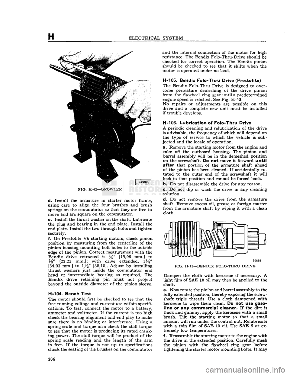
for shorted armature coils, a growler as
shown-in Fig. H-42 is necessary. The armature is placed against the core and a steel strip is held
on the armature. The growler is then energized 204
Page 206 of 376
H
ELECTRICAL
SYSTEM
FIG.
H-42—GROWLER
d.
Install
the armature in starter motor frame,
using care to align the four brushes and brush
springs on the commutator so that they are free to
move
and are square on the commutator.
e.
Install
the thrust washer on the shaft.
Lubricate
the plug and bearing in the end plate.
Install
the
end plate.
Install
the two through
bolts
and tighten securely.
f.
On Prestolite V6 starting motors, check pinion position by measuring from the centerline of the
pinion housing mounting bolt
holes
to the outside
edge
of the pinion.
Correct
measurement with the
Bendix
drive retracted is [19,05 mm.] to
%"
[22,23 mm.]; with drive extended, 1%"
[34,93
mm.] to 1^" [38,10]. Adjust by installing
thrust
washers just inside the commutator end
head or intermediate bearing as required. The
Bendix
drive retaining pin must not project
beyond the outside diameter of the pinion
sleeve.
H-104.
Bench Test
The
motor should first be checked to see that the
free running
voltage
and current are within specifi cations. To
test,
connect the motor to a battery,
ammeter and voltmeter. If the current is too high
check
the bearing alignment and end play to make
sure
there is no binding or interference. Using a
spring
scale and torque arm check the stall torque to see that the motor is producing its rated
crank
ing power. The stall torque
will
be product of the
spring
scale reading and the length of the arm
in
feet.
If the torque is not up to specifications
check
the seating of the brushes on the commutator
and
the internal connection of the motor for high
resistance. The Bendix
Folo-Thru-Drive
should be checked for correct operation. The Bendix pinion
should be checked to see that it shifts when the motor is operated under no load.
H-105.
Bendix Folo-Thru Drive (Prestolite)
The
Bendix
Folo-Thru
Drive is designed to over
come
premature demeshing of the drive pinion
from
the flywheel ring gear until a predetermined
engine
speed is reached. See Fig. H-43. No repairs or adjustments are possible on this
drive
and a
complete
new unit must be installed
if
trouble develops.
H-106.
Lubrication
of
Folo-Thru Drive
A
periodic cleaning and relubrication of the drive is advisable, the frequency of which
will
depend on
the type of service to which the vehicle is sub
jected and the locale of operation.
a.
Remove the starting motor from the
engine
and take off the outboard housing. The pinion and
barrel
assembly
will
be in the demeshed position
on the screwshaft. Do not
move
it forward
until
after
that portion of the armature shaft ahead
of the pinion has been cleaned. If accidentally ro
tated to the outer end of the screwshaft it
will
lock
in that position and cannot be forced back.
b.
Do not disassemble the drive for any reason.
c.
Do not dip or wash the drive in any cleaning solution.
d.
Do not remove the drive from the armature
shaft. Remove
excess
oil, grease or foreign matter
from
the armature shaft by wiping it with a clean cloth.
3
10859
FIG.
H-43—BENDIX
FOLO-THRU DRIVE
Dampen
the cloth with kerosene if necessary. A
light film of
SAE
10 oil may then be applied to the shaft.
e.
Now rotate the pinion and
barrel
assembly to the
fully
extended position, thereby exposing the screw shaft triple threads. Use a cloth dampened with
kerosene to wipe them clean. Do not use
gaso
line
or any
commercial cleaner.
If the dirt is
thick
and gummy, apply the kerosene with a small
brush.
Tilt
the starting motor so that a small
amount
will
run under the control nut. Relubricate
with
a thin film of
SAE
10 oil. Use SAE 5 at ex tremely low temperatures.
f.
Reassemble the starting motor to the
engine
with the drive in the extended position.
Carefully
mesh the pinion with the flywheel ring gear before
tightening the starter motor mounting bolts. It may 206
Page 208 of 376
H
ELECTRICAL
SYSTEM
sibility
of the cable shorting at the
engine
or frame.
Remove nut and lock washer securing the ignition
wire
to the solenoid
post
and remove the two screws and lock washers securing the solenoid to
the starter frame. Remove the switch,
b.
To install the solenoid switch reverse the re
moval
procedure given above.
H-10S.
STARTING MOTOR
—
DELCO
DAUNTLESS
V-6
ENGINE
Refer
to Fig. H-45.
The
starting motor used on the Dauntless V-6 en
gine
has an integral solenoid switch and enclosed
shift lever which first shifts the overrunning clutch
pinion into
engagement
with the ring gear on the
flywheel of the
engine
and then
closes
the electrical
circuit
to cause
engine
cranking. When the
engine
starts,
the overrunning clutch
disengages
to pre vent transfer of
engine
speed to the starting motor.
Note:
Should a service replacement starter motor
be required the factory recommends replacement
with
original equipment parts; however, should the need arise an existing starter motor (Delco or
Prestolite) could be replaced with the current
Delco-Remy
starter, model 1108375, with the
following modifications to the wiring harness. If
the existing starter motor wiring harness
does
not
provide a 12 ga. purple conduit wire, (connects the ignition switch to the starter motor) then a 12 ga.
purple
conduit wire 70 inches long, must be in
stalled.
Should the existing starter motor wiring
harness
contain a 16 ga. light blue conduit wire, (connects the ignition switch and starter motor)
bend this wire back and tape out of the way.
H-109.
Starting Motor Disassembly
a.
Before removing the starting motor from the
engine, disconnect leads and cover battery lead
terminal
with piece of
hose
or tape to prevent
short circuiting.
Note
locations of wiring connec
tions to assure proper reconnection. Remove the cap screw that secures the starting motor to the
angle bracket on the side of the engine. Remove
the two cap screws that secure the drive end of
the starting motor to the cylinder block; remove
the starting motor.
b.
Remove terminal nut and disconnect field lead,
which
passes through grommet at top of motor,
from
motor terminal of solenoid. Remove two
thru
bolts
from motor. Remove commutator end frame
and
field frame assembly from solenoid and drive assembly.
e.
Pull
out pivot pins of brush holders and remove each of two brush holder and spring assemblies
from
field housing. Remove screws which attach
brushes and leads to holders.
d.
Remove armature and drive assembly from
drive
housing. Remove thrust collar from pinion
end of armature shaft. Remove leather thrust
washer
from
opposite
end of shaft.
e. To separate drive assembly from
armature,
place
a
metal cylinder of proper size (J^" [12,7 mm.]
pipe coupling is satisfactory) over end of armature
shaft to bear against the pinion
stop
retainer. Tap
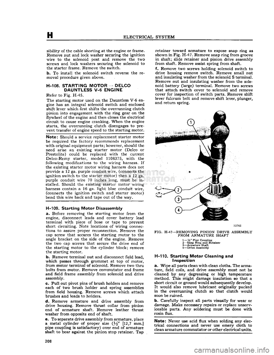
retainer
toward armature to
expose
snap ring as
shown in
Fig.
H-47. Remove snap ring from
groove
in
shaft; slide retainer and pinion drive assembly
from
shaft. Remove assist spring from shaft,
f.
Remove two screws holding solenoid switch to
drive
housing remove switch. Remove small nut
and
insulating washer from the solenoid S terminal.
Remove nut and insulating washer from the
sole
noid battery (large) terminal. Remove two screws that attach switch cover to solenoid and remove cover for inspection of switch parts. Remove shift
lever fulcrum bolt and remove shift lever, plunger,
and
return spring.
12765
FIG.
H-47—REMOVING PINION
DRIVE
ASSEMBLY
FROM
ARMATURE SHAFT
1— XA ' Pipe Coupling
2—
Snap
Ring
and Retainer
3—
Armature
Shaft
4—
Drive
Assembly
H-110.
Starting
Motor
Cleaning and
Inspection
a.
Wipe all parts clean with clean cloths. The
arma
ture,
field coils, and drive assembly must not be
cleaned by any degreasing or high temperature
method.
This
might damage insulation so that a
short
circuit
or ground would subsequently develop.
It
would also remove lubricant originally packed
in
the overrunning clutch so that clutch would
soon
be ruined.
b.
Carefully
inspect all parts visually for wear or
damage. Make necessary repairs or replace unserv
iceable parts. Any soldering must be
done
with
rosin
flux.
Note:
Never use acid flux when solding any elec
trical
connections and never use emery cloth to
clean
armature
commutator or other
electrical
units. 208
Page 210 of 376
H
ELECTRICAL
SYSTEM
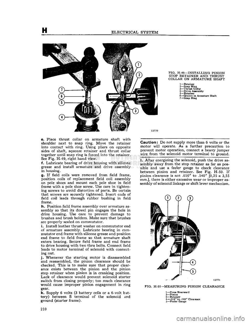
FIG.
H-49—INSTALLING PINION
STOP RETAINER AND THRUST
COLLAR
ON ARMATURE SHAFT
1—
Retainer
2—
Snap
Ring
3—
Thrust
Collar
4—
Drive
Assembly 5—
Retainer
6—
Groove
in Armature Shaft 7—
Snap
Ring
e. Place thrust collar on armature shaft with shoulder next to snap
ring.
Move the retainer
into contact with
ring.
Using pliers on
opposite
sides of shaft,
squeeze
retainer and thrust collar
together
until snap ring is forced into the retainer.
See Fig. H-49, right hand view.
f.
Lubricate
bearing of drive housing with silicone grease and install armature and drive assembly
in
housing.
g. If field coils were removed from field frame, position coils of replacement field coil assembly
on
pole
shoes
and mount each
pole
shoe
in field
frame
with a
pole
shoe
screw. Use care in tighten ing screws to avoid distortion of parts. Be certain
that screws are securely tightened. Insert ends of
field
coil
leads through rubber bushing in field
frame.
h.
Position field frame assembly over armature as
sembly so that its dowel pin
engages
the
hole
in
drive
housing. Use care to prevent damage to brushes and brush holders. Make sure that brushes
are
properly sealed on commutator.
i.
Install
leather thrust washer on commutator end
of armature assembly.
Lubricate
bearing in com
mutator end frame with silicone grease and position
end frame to field frame so that armature shaft
enters bearing. Secure field frame and end frame
to drive housing with two
thru
bolts. Connect field leads to motor terminal of solenoid with connecting nut.
j.
Whenever the starting motor is disassembled
and
reassembled, the pinion clearance should be
checked.
This
is to make sure that proper clear
ance exists
between
the pinion and the pinion
stop
retainer when pinion is in cranking position.
Lack
of clearance would prevent solenoid starter
switch
from closing properly; too much clearance
would cause improper pinion
engagement
in ring gear.
k.
Supply 6 volts (3 battery cells or a
6-volt
bat
tery)
between
S terminal of the solenoid and ground (starter frame).
Caution:
Do not supply more than 6 volts or the
motor
will
operate. As a further precaution to
prevent motor operation, connect a heavy jumper
wire
from the solenoid motor terminal to ground.
I.
After energizing the solenoid, push the drive as
sembly away from the
stop
retainer as far as pos
sible and use a feeler
gauge
to check clearance
between
pinion and retainer. See Fig. H-50. If pinion clearance is not .010" to .140" [0,25 a 3,55
mm.],
there is either excessive wear or improper as
sembly of solenoid linkage or shift lever mechanism.
12771
FIG.
H-50—MEASURING PINION CLEARANCE
1—
Press
Rearward
2—
Pinion
3—
Retainer
4— .010* to .140* Clearance 5—
Feeler
Gauge
210
Page 211 of 376
'Jeep'
UNIVERSAL
SERIES SERVICE
MANUAL
H
Note:
Pinion clearance cannot be adjusted. If
clearance is not correct, motor must be disassem
bled and checked for the above mentioned defects.
Any
defective parts must be replaced.
H-118. Starting Motor Test —
Genera!
To
obtain
full
performance data on a starting motor, or to determine the cause of abnormal
operation, the motor should be submitted to no-
load and locked armature
tests,
with equipment designed for such
tests.
A high-current variable resistance is required to obtain the specified volt
age at the starting motor.
This
is necessary since
a
small variation in the
voltage
will
produce a
marked
difference in the current
drawn.
H-119.
Starting Motor No-Load Test
This
test
requires a DC voltmeter capable of
read
ing
voltages
in a 12-volt
circuit,
a DC ammeter
with
maximum range of several hundred amperes,
a
high-current variable resistance, an rpm. in
dicator,
and a fully-charged, 12-volt battery.
a.
Connect a jumper lead
between
S terminal
and
large battery terminal of starter solenoid.
Con
nect voltmeter
between
either of
these
terminals (positive) and motor frame (negative, ground).
Connect
ammeter and variable resistance in series
between
positive terminal of battery and battery
terminal
of solenoid. Set up rpm. indicator to show starting motor speed.
b.
Initially,
adjust variable resistance to a value of
approximately .25 ohm. To complete the
circuit,
connect negative terminal of battery to motor
frame.
Adjust variable resistance to obtain a volt meter reading of 10.6 volts;
note
speed of starting motor and ammeter reading. Motor speed should
be
6750
to
10,500
rpm.; ammeter reading should
be 50 to 80 amperes.
c. Rated speed and current indicate normal condi
tion of the starting motor. Low speed and high
cur
rent
may show friction; this could be caused by
tight, dirty, or worn bearings, bent armature shaft,
or
a
loose
field
pole
shoe
dragging against the
armature.
It could also be caused by a short-cir cuited armature, or by grounded armature or field
coils.
d.
Failure
to operate and high current indicates
a
direct short circuit to ground at either the battery
terminal
or field coils.
e.
Failure
to operate and no current are usually
caused by broken brush springs, worn brushes, high insulation
between
commutator
bars,
or
some
other
condition preventing
good
contact
between
the brushes and commutator. It can also be caused by
open circuit in either the field coils or armature coils.
f. Low speed and low current show high resistance due to poor connections, defective leads, dirty com
mutator, or one of the conditions mentioned in e,
above.
g. High speed and high current indicates a short
circuit
in the field coils. H-120-
Locked
Armature Test
This
test
requires a DC voltmeter with range ap
propriate
to read
voltages
in a 12-volt
circuit,
a DC
ammeter with maximum range of several hundred
amperes, a high-current variable resistance, a
clamping fixture to lock
together
the motor shaft
and
case, and a fully-charged 12-volt battery.
a.
Connect a jumper lead
between
S terminal and
large battery terminal of starter solenoid. Connect
voltmeter
between
either of
these
terminals (posi
tive) and motor frame (negative, ground). Connect
ammeter and variable resistance in series
between
positive terminal of battery and battery terminal
of solenoid.
Install
clamping fixture to lock motor
shaft and case
together
securely.
b.
Initially,
adjust variable resistance to approxi
mately .05 ohm. To complete the
circuit,
connect
negative terminal of battery to motor frame. Ad
just
variable resistance to obtain a voltmeter
read
ing of 4.0 volts. Ammeter reading should be 280
to 320 amperes.
H-121.
Solenoid Starter Switch — Delco
The
solenoid-type switch is mounted directly on
the starting motor.
This
type of switch is energized
by turning the ignition key to the extreme right position. Should the solenoid switch
fail
in service
it
is necessary to install a new assembly.
Should
a starting motor
fail
to deliver maximum power the fault may be due to
voltage
drop at the
starter
switch contacts due to corrosion or burning.
Check
the switch by comparing the
voltage
at the
battery across the terminals. The
voltage
drop
should not exceed .05 volts per 100 amperes.
In
order to remove the starter solenoid, it is neces
sary
to remove the starter assembly.
H-122.
ELECTRICAL
INSTRUMENTS
H-123.
Fuel
Gauge —
CJ-3B
The
fuel
gauge
circuit is composed of the indicating
unit,
mounted on the instrument panel, and the
fuel tank unit, connected by a single wire through the ignition switch.
Should
the
gauge
fail
to register, check all wire con nections to be sure they are tight and clean; also
be sure both units are well grounded. If, after this
check, the
gauge
does
not indicate properly, remove
the wire from the tank unit and connect it to a
new tank unit which must be grounded to the tank
or
frame for
test.
Turn
the ignition switch "ON"
and
move
the float arm through its range of travel,
watching the dash unit to determine if it indicates
correctly.
If it fails to do so the trouble is probably
in
the dash unit and it should be replaced.
Should
a new tank unit be unavailable for this
test,
disconnect tank unit wire at the instrument panel
gauge.
Connect one lead of a 12 V, 1 CP
test
light
to the instrument panel unit terminal and with the
ignition switch
"ON"
ground the other lead. If the
unit is operating correctly the pointer
will
move
approximately three-quarter across the
dial.
Do not attempt to repair either unit; replacement
is the only precedure. 211
Page 212 of 376
H
ELECTRICAL
SYSTEM
H-124. Testing Indicators and Gauges
Two
gauges
(fuel and temperature) and two in dicators (oil pressure and battery charge) that are
located in the instrument cluster are electrically operated.
The
fuel
gauge
is connected by a single wire to a
float-and-slide-rheostat sending unit in the fuel
tank.
The
temperature
gauge
is connected by a single
wire
to a resistance-type sending unit mounted on the engine.
The
battery charge indicator operates when there
is a difference in potential
between
the generator
and
the battery
.The
battery charge indicator lights
when the generator is not charging the battery. The
indicator
light
goes
out when the generator
begins
to charge the battery.
The
oil pressure indicator is connected by a single
wire
to a diaphragm switch located on the engine.
When
engine
oil pressure is low or zero and the
ignition switch is on, the oil pressure indicator
will
light. When
engine
speed is increased slightly above idle speed, raising the oil pressure to approximately 6 psi. [0,2 kg-cm2], the diaphragm switch
will
open the circuit and the indicator light
will
go out.
A
voltage
regulator maintains a constant
voltage
to the
gauges
in normal operation. On early vehicles,
this
voltage
regulator was mounted on the
rear
of
the instrument cluster. On current vehicles, the
voltage
regulator is integral with the fuel
gauge.
Should
trouble
develop
in the
gauges,
first check the regulator (fuel
gauge
on current production vehicle). If the
voltage
to the regulator is below 10 volts system low
gauge
readings
will
result.
Voltage in
excess
of 16 volts
will
not affect
gauge
readings but may result in premature wear of the
regulator contacts. If the
voltage
to the regulator is
within
the above limits, check the electrical con nections to the regulator (or fuel gauge), especially
the ground connection. If the readings of all the
gauges
is too high, or they all read too low, replace
the regulator (or fuel gauge).
If
the temperature
gauge
or heat indicator in the
instrument cluster have failed, the cause may
originate from the jumper bar shorting out against the instrument case.
Check
the jumper bar
between
the temperature
gauge
and heat indicator at the
rear
of the instrument case. On later production vehicles, the jumper bar is covered with an in
sulating
sleeve
to protect it from shorting out
against the instrument case. If the jumper bar
does
not have this
sleeve,
either install one or
wrap
the bar with plastic electrical tape to
half
an
inch [12,7 mm.] from each end. When installing the jumper bar, be sure the curved
segment
is
closest to the fuel
gauge.
Should
only one of the two
gauges
register incor
rectly,
check the lead wire from the
gauge
to the
sending unit for shorts or open connections. Next disconnect the
gauge
from the sending unit, and
connect the
gauge
to a new fuel tank sending unit
which
has been grounded to the vehicle.
If
the
gauge
registers incorrectly when operating the new unit,
replace the
gauge;
if correctly, replace the sending
unit.
Should
a new fuel tank unit not be available for testing, use a 12-volt
test
light in its place. When
the
gauge
is operating correctly, the pointer
will
move
approximately three-quarters across the
dial.
On
some
vehicles, the temperature
gauge
may
register on or
close
to the H (hot)
mark
when
coolant temperature is
190°F.
to
200°F.
[88°C.
a
93°C.].
In such cases, a 25-ohm,
1-watt
resistor
may be installed on the temperature
gauge
which
will
place the pointer just beyond the center
mark
at a coolant temperature of
190°F.
to
200°F.
Install
the resistor
between
the two terminals on the back
of the
gauge.
Insulate the
exposed
leads of the resistor with electrical tape.
If
the oil pressure indicator
does
not indicate cor
rectly,
first check the light bulb. Next check all
connections and lead wires. If, after all possible
defects
are corrected, the indicator light
does
not go on and off properly, then the diaphragm type
switch in the cylinder block should be replaced.
H-12S.
LIGHTING SYSTEM The
wiring of the lighting systems is shown in
the wiring diagrams, which indicate the various units in relation to their positions in the vehicle.
The
wires in the various circuits are of different
colors or are marked by tracers to aid when check
ing individual circuits.
The
lighting circuits of all models are protected by
an
overload circuit breaker mounted on the back of the main light switch and no replaceable fuse is
required.
The
upper and lower headlight beams are con
trolled by a
foot
switch located on the toe board
to the left of the clutch pedal.
H-126.
Main
Light
Switch
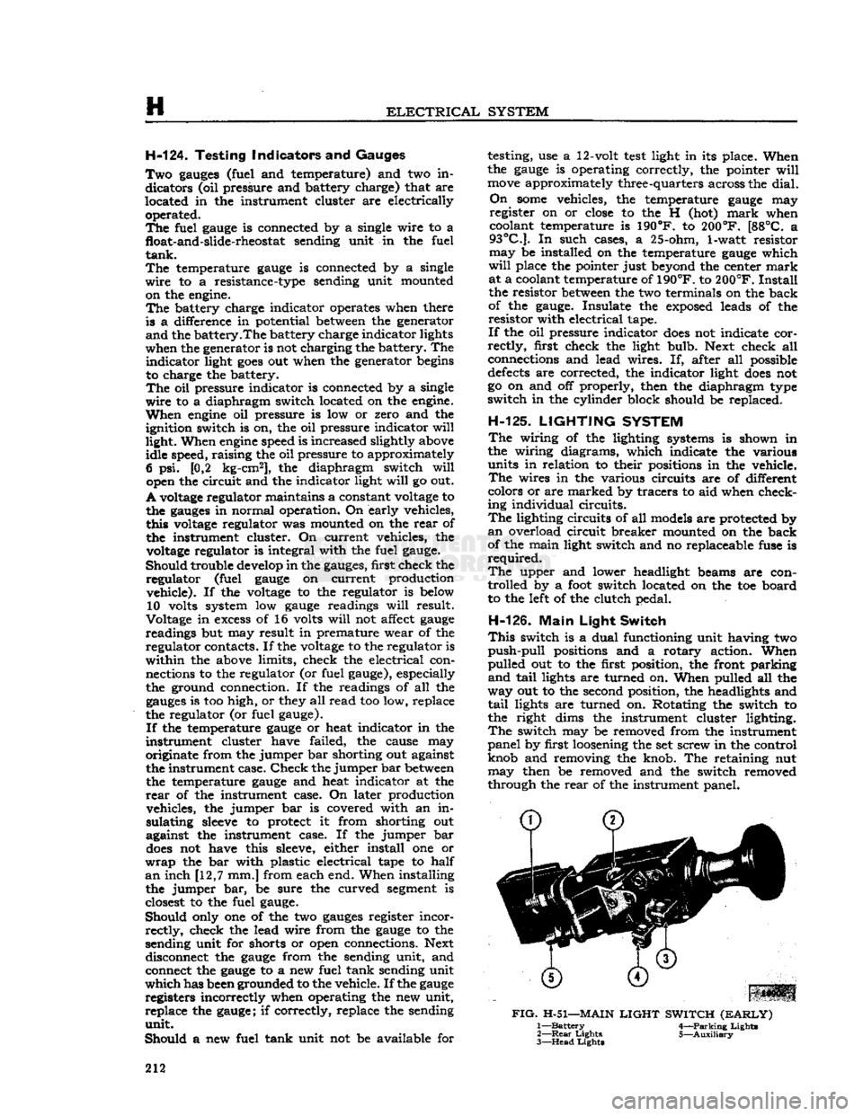
This
switch is a dual functioning unit having two
push-pull
positions and a rotary action. When
pulled out to the first position, the front parking
and
tail
lights are turned on. When pulled all the
way out to the second position, the headlights and
tail
lights are turned on. Rotating the switch to
the right dims the instrument cluster lighting.
The
switch may be removed from the instrument
panel by first loosening the set screw in the control
knob and removing the knob. The retaining nut may then be removed and the switch removed
through the
rear
of the instrument panel.
FIG.
H-51—MAIN
LIGHT
SWITCH
(EARLY)
1—
Battery
4—Parking Lights
2—
Rear
Lights 5—Auxiliary
3—
Head
Lights
212
Page 214 of 376

H
ELECTRICAL
SYSTEM
14379
FIG.
H-56—PARKING
AND SIGNAL LIGHT (LATE) 1—
Screw
2—
Lens
3—
Gasket
4—
Bulb
5—
Cable
6— Housing H-131. Head
Lamp
Aiming Preparation
All
Jeep Universal-series lamps must be aimed on
the low beam. Lamps may be aimed either with mechanical aimers or by using a screen. If me
chanical
aimers C-3674 are used,
follow
instruction
supplied with the aiming equipment. If a screen is to be used, preparation for aiming is as follows:
a.
Locate the vehicle in a darkened area with a level floor area and with a screen (may be a wall) having a nonreflecting white surface. A reference
line should be marked on the floor 25
feet
[7,62 m.]
away from and parallel to the screen. Position the vehicle perpendicular to the screen and with the
front head lamps directly over the reference line.
b. Locate the middle
tape
on the screen so that
it is aligned with the center line of the vehicle.
c. Equalize all tire pressures.
d.
Rock the vehicle from side to side to equalize springs and shock absorbers.
e. Measure the distance
between
vehicle head lamp centers.
Then,
position marker
tapes
vertically on
the screen to the right and
left
of the middle
tape
at half this distance.
f.
Measure the distance from the center of each
lamp to the surface on which the vehicle rests.
Position a marker
tape
horizontally on the screen
FIG.
H-57—TAIL, STOP AND
DIRECTIONAL
LIGHT
1—
Screw
2—
Lens
3—
Gasket
4—
Bulb
5— Housing and Cable Assembly
6— Nut and Lockwasher 10441
FIG.
H-58—TAIL AND
STOP LIGHT (EARLY)
1
—Ring
2—
Lens
3—
Gasket
4—
Retainer
5—
Bulb
6—
Gasket
7— Housing and Socket 214
Page 216 of 376
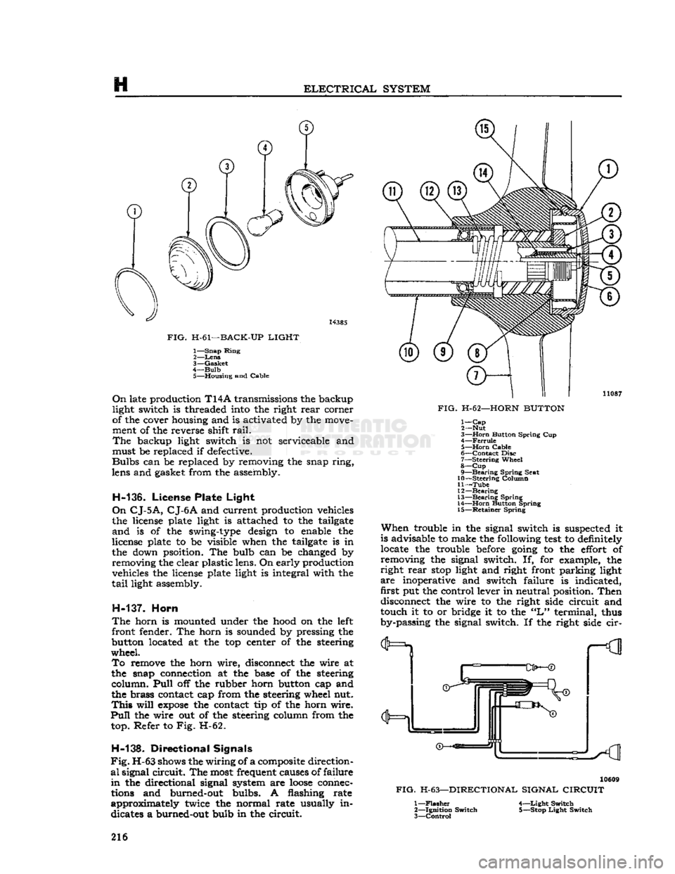
ELECTRICAL
SYSTEM
14385
FIG.
H-61—BACK-UP
LIGHT
1—
Snap
Ring
2—
Lens
3—
Gasket
4—
Bulb
5—
Housing
and
Cable
On
late production
T14A
transmissions the backup
light switch is threaded into the right
rear
corner
of the cover housing and is activated by the move
ment of the reverse shift
rail.
The
backup light switch is not serviceable and
must be replaced if defective.
Bulbs
can be replaced by removing the snap
ring,
lens and gasket from the assembly.
H-136.
License Plate
Light
On
CJ-5A,
CJ-6A
and current production vehicles
the license plate light is attached to the tailgate
and
is of the swing-type design to enable the
license plate to be visible when the tailgate is in
the down psoition. The bulb can be changed by
removing
the clear plastic lens. On early production
vehicles the license plate light is integral with the
tail
light assembly.
H-137.
Horn
The
horn is mounted under the hood on the
left
front
fender. The horn is sounded by pressing the
button located at the top center of the steering
wheel.
To
remove the horn wire, disconnect the wire at
the snap connection at the base of the steering
column.
Pull
off the rubber horn button cap and
the brass contact cap from the steering wheel nut.
This
will
expose
the contact tip of the horn wire.
Pull
the wire out of the steering column from the top. Refer to Fig. H-62.
H-13S.
Directional
Signals
Fig.
H-63 shows the
wiring
of a
composite
direction
al
signal
circuit.
The most frequent causes of
failure
in
the directional signal system are
loose
connec
tions and burned-out bulbs. A flashing rate
approximately
twice the normal rate usually in
dicates a burned-out bulb in the
circuit.
11087
FIG.
H-62—HORN
BUTTON 1—
Cap
2— Nut
3—
Horn
Button
Spring
Cup 4—
Ferrule
5—
Horn
Cable
6—
Contact
Disc
7—
Steering
Wheel
8—
Cup
9—
Bearing
Spring
Seat
10—
Steering
Column
11—
Tube
12—
Bearing
13—
Bearing
Spring
14—
Horn
Button
Spring
15—
Retainer
Spring
When
trouble in the signal switch is suspected it
is advisable to make the following
test
to definitely
locate the trouble before
going
to the effort of
removing
the signal switch. If, for example, the
right
rear
stop
light and right front parking light
are
inoperative and switch failure is indicated, first put the control lever in neutral position.
Then
disconnect the wire to the right side
circuit
and
touch it to or bridge it to the
"L"
terminal, thus
by-passing the signal switch. If the right side cir- 10609
FIG.
H-63—DIRECTIONAL SIGNAL
CIRCUIT
1—
Flasher
2—
Ignition
Switch
3—
Control
4—
Light
Switch
5— Stop
Light
Switch
216