Electrical JEEP CJ 1953 Workshop Manual
[x] Cancel search | Manufacturer: JEEP, Model Year: 1953, Model line: CJ, Model: JEEP CJ 1953Pages: 376, PDF Size: 19.96 MB
Page 218 of 376

ELECTRICAL
SYSTEM
FIG.
H-66—WINDSHIELD
WIPER SWITCH ASSEMBLY (LATE)
B—Battery
1—
Wiper
1 La
Speed
2—
Wiper
1 Hi
Speed
3—
Wiper
2 Lo
Speed
4—Wiper
2 Hi
Speed
5— Park
g. If wiper operates erratically, check for
loose
wiper
ground connection or
loose
dash switch mounting.
H-145.
Wiper Troubleshooting on Bench
Using
ammeter, capable of reading at least 30
amperes, check
feed
wire circuit for open circuit.
a.
If wiper is inoperative, connect wiper to operate
in
low speed and observe current draw. If the read
ing is zero amp., check for
loose
solder connection
at wiper terminal or
loose
splice joints. If reading is
1
to 1.5 amp., check for open armature, sticking
brushes, or
loose
splice joint. If reading is 11 amp.,
check for broken gear seized shaft or
some
other
condition that
will
stall the wiper.
b. If wiper
will
not shut off, this condition may
exist if wiper has one or both speeds. If wiper has both speeds, check for
park
switch contacts not
opening or internal wiper motor lead that connects to wiper terminal being grounded. If wiper has low
speed only, check for internal wiper motor lead that connects to wiper terminal being grounded. If
wiper
has high speed only, check for
internal
wiper motor lead that connects to wiper terminal being
open.
c.
If wiper
crank
arm
does
not return to
park
position when wiper is turned off, check for dirty, bent to broken
park
switch contacts.
d.
If wiper operates erratically, check for sticky
brushes or
loose
splice joints.
e. If the wiper
will
not shut off, or wiper
crank
arm
fails to
stop
in
park
position when jumper wire is
removed from terminal, check that
park
switch contacts are opening. Also check for ground in in
ternal
motor lead that connects to terminal.
f-
Remove fastening screws, cover plate assembly
and
gasket.
g. Remove parking plate and gear assembly.
h.
Remove parking brushes, spring and bowed
washer from gear assembly.
i.
Remove the two through
bolts
and mounting
bracket.
j.
Remove the magnet housing, armature and end cap as an assembly.
k.
Tap end of armature shaft to
loosen
end cap
assembly and remove cap from armature shaft. Be
careful
not to
lose
thrust disc, which is in end cap
bearing bore.
I.
Remove armature from magnet housing.
Care
should be taken to protect armature shaft bearing
journals.
m.
Remove brushes and brush spring from brush
holders.
H-147.
Cleaning
of
Two-Speed
Wiper
Motor
a.
Clean
magnet housing and
armature
with a cloth dampened in cleaning solvent.
b.
The following bearing equipped parts should
not
be immersed in cleaning fluid: 1. Cover plate assembly.
2.
Gear
housing assembly.
3.
End cap assembly.
The
metal surfaces of
these
assemblies should be cleaned with a brush dipped in cleaning solvent,
making
certain that cleaning fluid
does
not contact bearings.
c.
Clean
remaining parts with a brush and cleaning
solvent.
H-148.
Reassembly
of
Two-Speed
Wiper
Motor
Refer
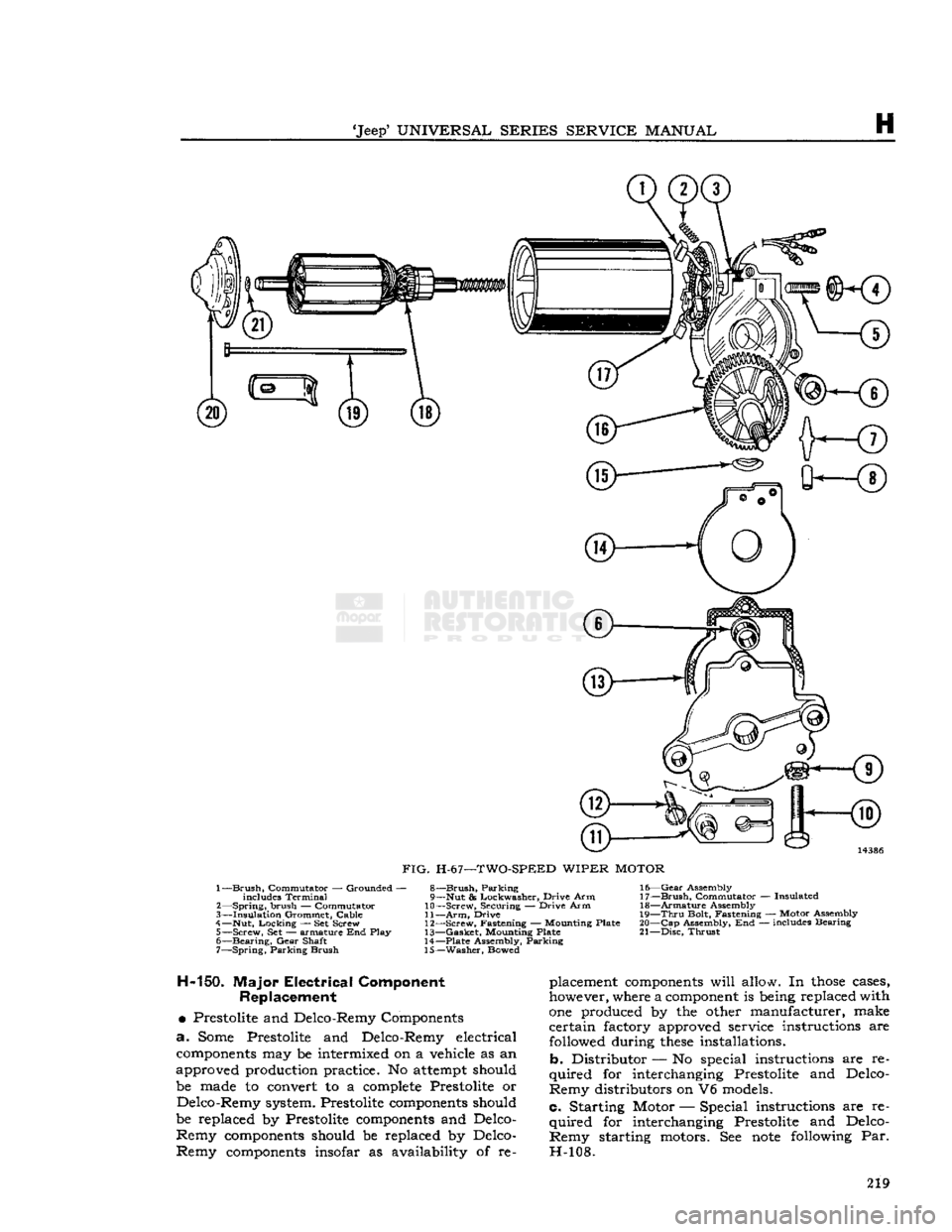
to Fig. H-67.
To
reassemble motor, reverse the
steps
given in
Par.
H-146.
When
reassembling motor, fingers must be clean
when handling brushes. Hold brushes in the holders by applying paper clips to brush shunts. Apply a
light film of lubricant to armature shaft ends,
armature
worm gear and gear assembly shaft ends.
Remove paper clips after assembling armature to gear housing. Align marks on magnet housing and
gear housing. Armature end play should be .002 -
.010".
Be
sure to operate wiper to
park
position prior to installing drive arm.
H-146.
Disassembly
of
Two-Speed Wiper Motor
Refer
to Fig. H-67.
a.
Remove windshield wiper motor cover.
b.
Disconnect drive arm from wiper linkage.
c.
Disconnect wiring from wiper dash switch.
d.
Remove wiper motor.
e.
Loosen drive arm hardware and pry drive off
drive
shaft.
H-149.
No
Load
Testing
Test
the motor to
meet
the following specifications:
LOW SPEED HIGH SPEED
Ampere Ampere
Draw Draw
R.P.M.
(Max.)
R.P.M.
(Max.)
42 2.75 62 3.75 218
Page 219 of 376
'Jeep'
UNIVERSAL
SERIES SERVICE
MANUAL
H
a
0"—®
FIG.
H-67—-TWO-SPEED
WIPER
MOTOR
1—
Brush,
Commutator — Grounded - includes Terminal
2—
Spring,
brush — Commutator
3—
Insulation
Grommet, Cable
4—
Nut,
Locking
— Set Screw
5— Screw, Set — armature End Play
6—
Bearing,
Gear
Shaft
7—
Spring,
Parking Brush 8—
Brush,
Parking
9—
Nut
& Lockwasher,
Drive
Arm
10—
Screw, Securing —
Drive
Arm
11—
Arm,
Drive
12—
Screw, Fastening — Mounting
Plate
13—
Gasket,
Mounting
Plate
14—
Plate
Assembly, Parking
15—
Washer, Bowed
16—
Gear
Assembly
17—
Brush,
Commutator — Insulated
18—
Armature
Assembly
19—
Thru
Bolt,
Fastening — Motor Assembly
20—
Cap Assembly, End — includes Bearing
21—
Disc,
Thrust H-150. Major
Electrical
Component
Replacement
•
Prestolite and Delco-Remy Components
a.
Some
Prestolite and Delco-Remy electrical
components may be intermixed on a vehicle as an
approved production practice. No attempt should
be
made
to convert to a complete Prestolite or Delco-Remy system. Prestolite components should
be replaced by Prestolite components and Delco- Remy components should be replaced by Delco-
Remy components insofar as
availability
of re placement components
will
allow.
In
those
cases,
however, where a component is being replaced
with
one produced by the other manufacturer, make
certain factory approved service instructions are
followed
during
these
installations.
b. Distributor — No special instructions are re
quired
for interchanging Prestolite and Delco-
Remy distributors on V6 models.
c. Starting Motor — Special instructions are re
quired
for interchanging Prestolite and Delco-
Remy starting motors. See note
following
Par.
H-108. 219
Page 220 of 376
H
ELECTRICAL
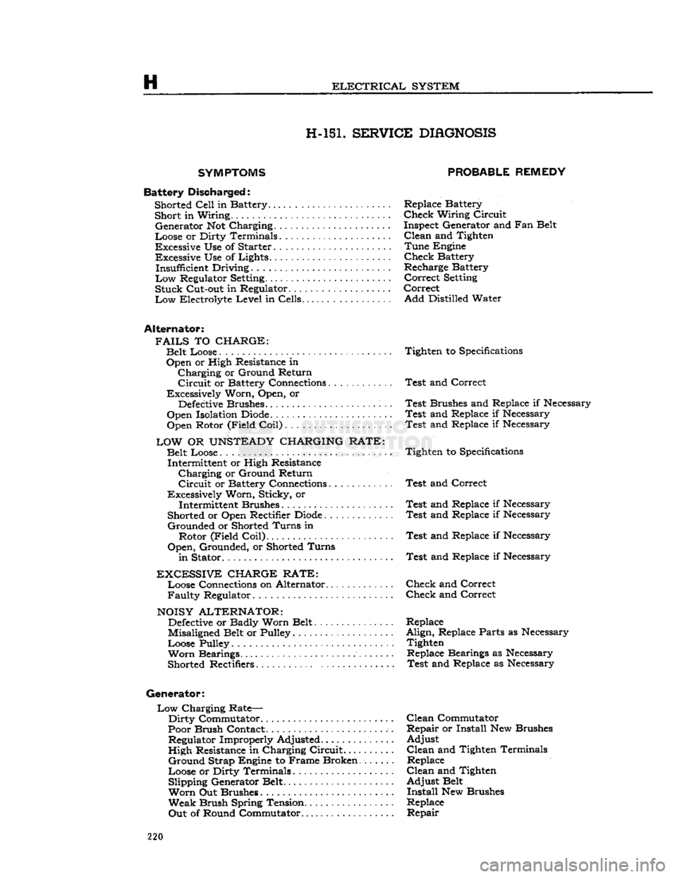
SYSTEM H-15L SERVICE
DIAGNOSIS
SYMPTOMS
Battery
Discha
rged: Shorted
Cell
in Battery......... Short in Wiring..
•
Generator Not Charging ,
Loose or Dirty Terminals
Excessive Use of Starter Excessive Use of Lights...... Insufficient Driving.........
Low
Regulator
Setting.......
Stuck
Cut-out in Regulator. ..
Low
Electrolyte
Level
in Cells
Alternator:
FAILS
TO
CHARGE:
Belt Loose Open or High Resistance in
Charging
or Ground Return
Circuit
or Battery Connections............
Excessively Worn, Open, or
Defective
Brushes.
Open Isolation
Diode.
Open Rotor (Field
Coil)
LOW
OR
UNSTEADY
CHARGING RATE:
Belt Loose.... Intermittent or High Resistance
Charging
or Ground Return
Circuit
or Battery Connections
Excessively Worn, Sticky, or Intermittent Brushes
Shorted or Open Rectifier
Diode
Grounded
or Shorted
Turns
in Rotor (Field
Coil)
Open,
Grounded, or Shorted
Turns
in
Stator
EXCESSIVE
CHARGE RATE:
Loose Connections on Alternator...........
Faulty
Regulator
NOISY
ALTERNATOR:
Defective
or Badly Worn Belt
Misaligned Belt or Pulley
Loose Pulley
Worn
Bearings.
Shorted Rectifiers
Generator:
Low
Charging Rate—
Dirty
Commutator
Poor Brush Contact.
................
Regulator Improperly Adjusted.......
High
Resistance in Charging
Circuit...
Ground
Strap Engine to Frame Broken
Loose or Dirty Terminals Slipping Generator Belt
Worn
Out Brushes
Weak
Brush Spring Tension..........
Out
of Round Commutator
PROBABLE REMEDY
Replace Battery
Check
Wiring
Circuit
Inspect Generator and Fan Belt
Clean
and Tighten
Tune
Engine
Check
Battery
Recharge Battery
Correct
Setting
Correct
Add
Distilled Water
Tighten to
Specifications
Test
and Correct
Test
Brushes and Replace if Necessary
Test
and Replace if Necessary
Test
and Replace if Necessary
Tighten to
Specifications
Test
and Correct
Test
and Replace if Necessary
Test
and Replace if Necessary
Test
and Replace if Necessary
Test
and Replace if Necessary
Check
and Correct
Check
and Correct
Replace
Align,
Replace Parts as Necessary Tighten Replace Bearings as Necessary
Test
and Replace as Necessary
Clean
Commutator
Repair
or Install New Brushes
Adjust
Clean
and Tighten Terminals Replace
Clean
and Tighten
Adjust
Belt
Install
New Brushes
Replace
Repair
220
Page 222 of 376

H
ELECTRICAL
SYSTEM
H-151.
SERVICE
DIAGNOSIS—Continued
SYMPTOMS
PROBABLE REMEDY
Horn
Fails
to Sound:
Broken
or Loose
Electrical
Connection Check Wiring and Connections at Horn Button and
Battery—Clean
and Tighten
Battery Low or Dead Check Battery Contact Points Burned or Broken Off. Replace Parts Necessary
Horn
Sounds Unsatisfactory Tone: Poor
Electrical
Connection Check Connections at Horn, Horn Button, Battery Battery Low Check with Hydrometer Loose Cover and Bracket Screws Tighten Bracket Bolts at Horn
Voltage at Horn too High or too Low Check with Voltmeter 222
Page 223 of 376
'Jeep'
UNIVERSAL SERIES SERVICE
MANUAL
H
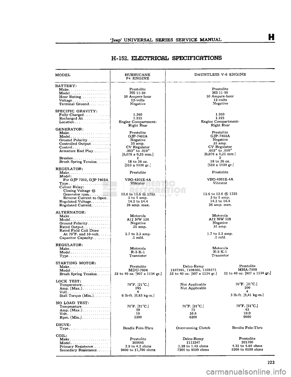
H-152.
ELECTRICAL
SPECIFICATIONS
MODEL HURRICANE
F4 ENGINE DAUNTLESS
V-6
ENGINE
BATTERY:
Make
Model Hour Rating.
Voltage
Terminal
Ground
SPECIFIC
GRAVITY:
Fully
Charged
Recharged At
Location
GENERATOR:
Make.
Model
Ground
Polarity
Controlled Output
Control
Armature End Play
Brushes
Brush
Spring Tension
REGULATOR:
Make
Model:
For
GJP
7202,
GJP
7402A
Type
Cutout Relay: Closing
Voltage
@
Generator rpm..........
Reverse Current to Open.
Regulated
Voltage
Regulated Current
ALTERNATOR:
Make
Model
Ground
Polarity
Rated Output
Rated Field
Coil
Draw
At
70°F.
and
10-volt
Capacitor Capacity
REGULATOR:
Make
Model
Type
STARTING
MOTOR:
Make
Model
Brush
Spring Tension
LOCK
TEST:
Temperature
Amp.
(Max.)
Volt
Stall
Torque (Min.)
NO LOAD TEST:
Tempesature
Amp.
(Max.)
Volt
Rpm.
(Min.)
DRIVE:
Type
COIL:
Make.
Model
Primary
Resistance Secondary Resistance
Prestolite
HS
11-50
50 Ampere-hour
12-volts
Negative
1.260
1.225
Engine Compartment- Right Rear
Prestolite
GJP-7402A
Negative
35 amp.
CV
Regulator .003" to .010"
[0,076
a 0,25 mm.] 2
18 to 36 oz.
[510 a 1020 gr.]
Prestolite
VBO-4201E-4A
Vibrator
12.6 to 13.6 @ 1325 3 to 5 amp. 14.2 to 14.4
36 amp. max.
Motorola
A12 NW 526
Negative
35 amp.
1.7 to 2.3 amp. .1 mfd.
Motorola
R-2-K-1
Transistor
Prestolite
MDU-7004
32 to 40 oz. [907 a 1134 gr.]
70°F.
[21°C] 295 4
6 lb-ft. [0,83
kg-m.]
70°F.
[21°C.;
50
10
5300
Bendix Folo-Thru
Prestolite
200691
3.9 to 4.2
ohms
9400
to
11,700
ohms
Prestolite
HS
11-50
50 Ampere-hour
12-volts
Negative
1.260
1.225
Engine Compartment- Right Rear
Prestolite
GJP-7402A
Negative
35 amp.
CV
Regulator .003" to .010"
[0,076
a 0,25 mm.] 2
18 to 36 oz.
[510 a 1020 gr.]
Prestolite
VBO-4201E-4A
Vibrator
12.6 to 13.6 @ 1325 3 to 5 amp. 14.2 to 14.4
36 amp. max.
Motorola
A12 NW 528
Negative
35 amp.
1.7 to 2.3 amp. .1 mfd.
Motorola
R-2-K-1
Transistor
Delco-Remy
1107391,
1108366,
1108375
32 to 40 oz. [907 a 1134 gr.]
Not Applicable Not Applicable
70°F.
[21°C] 75
10.6
6200
Overrunning Clutch Delco-Remy
1115247
1.28 to 1.42
ohms
7200
to
9500
ohms
Prestolite
MHA-7008
32 to 40 oz. [907 a 1134 gr.]
70°F.
[21°C] 200 4
3 lb-ft. [0,41
kg-m.]
70°F.
[21°C] 43
10.0
9000
Bendix Folo-Thru
Prestolite
201700
4.25 to 4.60
ohms
5200
to 6100
ohms
223
Page 224 of 376
H
ELECTRICAL
SYSTEM
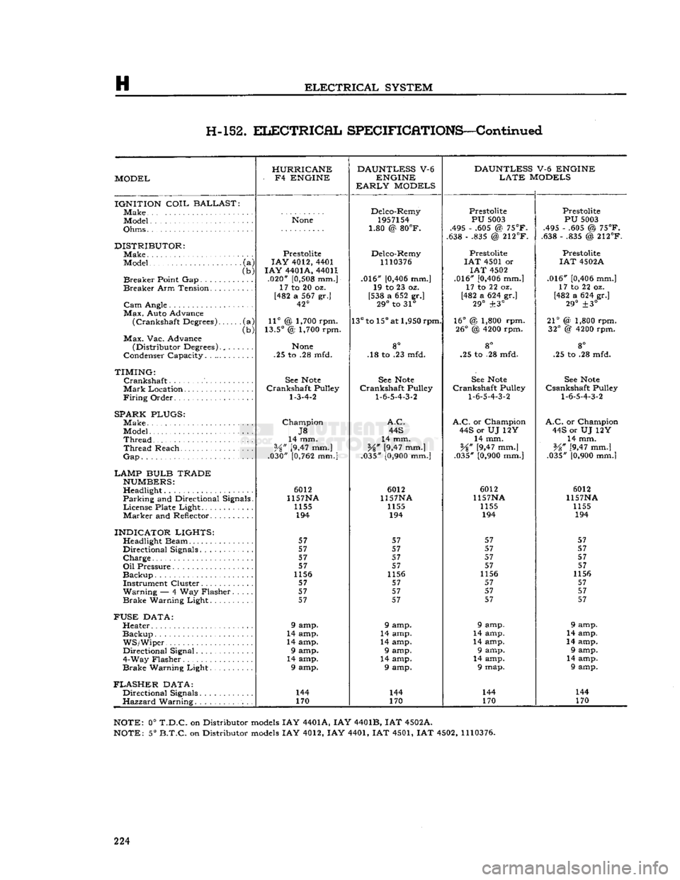
H-152.
ELECTRICAL
SPECIFICATIONS—Continued
HURRICANE DAUNTLESS
V-6
DAUNTLESS
V-6 ENGINE
MODEL -
F4
ENGINE
ENGINE
LATE
MODELS
EARLY
MODELS
IGNITION
COIL
BALLAST
]Make Delco-Remy
Prestolite Prestolite
Model
None
1957154
PU
5003
PU
5003
Ohms • • 1.80 @
80°F.
.495 - .605 @
75°F.
.495 - .605 @
75°F.
1.80 @
80°F.
.638 - .835 @
212°F.
.638 - .835 @
212°F.
DISTRIBUTOR:
Prestolite Delco-Remy Prestolite Prestolite
Model
•
(a)
LAY
4012, 4401
1110376
I
AT
4501 or
IAT
4502A
(b)
I
AY
4401A, 44011
IAT
4502
Breaker
Point Gap (b)
.020"
[0,508
mm.] .016"
[0,406
mm.] .016"
[0,406
mm.]
.016"
[0,406
mm.]
Breaker
Arm Tension. ..... 17 to 20 oz.
19 to 23 oz. 17 to 22 oz. 17 to 22 oz.
[482 a 567 gr.] [538 a 652 gr.] [482 a 624 gr.]
[482 a 624 gr.]
42° 29°
to 31°
29°
±3°
29°
±3°
Max.
Auto Advance
(Crankshaft
Degrees) •(a)
11°
@ 1,700 rpm.
13°
to
15°
at 1,950 rpm.
16°
@ 1,800 rpm.
21°
(2 1,800 rpm.
(Crankshaft
Degrees)
(b)
13.5°
@ 1,700 rpm.
26°
@
4200
rpm.
32°
@
4200
rpm.
Max.
Vac. Advance go
(Distributor Degrees)., . .
None
8° 8°
go
Condenser Capacity. . .25 to .28 mfd. .18 to .23 mfd. .25 to .28 mfd. .25 to .28 mfd.
TIMING:
Crankshaft
See
Note
See
Note
See
Note
See
Note
Mark
Location............
Crankshaft
Pulley
Crankshaft
Pulley
Crankshaft
Pulley
Csankshaft
Pulley
Firing
Order
1-3-4-2
1-6-5-4-3-2
1-6-5-4-3-2 1-6-5-4-3-2
SPARK PLUGS:
Make
Champion
A.C. A.C.
or Champion
A.C.
or Champion
J8
44S
44S or UJ 12Y 44S or UJ 12Y
Thread
14 mm.
14 mm. 14 mm. 14 mm.
Thread
Reach
Vz"
[9,47 mm.]
%"
[9,47 mm.]
¥%"
[9,47 mm.]
V8" [9,47 mm.]
Gap
.030"
[0,762
mm.]
.035"
[0,900
mm.] .035"
[0,900
mm.] .035"
[0,900
mm.|
LAMP BULB TRADE
NUMBERS:
Headlight 6012
6012 6012 6012
Parking
and Directional Signals. 1157NA
1157NA 1157NA 1157NA
License
Plate Light........ 1155
1155 1155 1155
Marker
and Reflector 194
194 194 194
INDICATOR LIGHTS:
57 57 57 57
Directional Signals........ 57
57 57 57
Charge
57
57 57 57
57 57 57 57
1156 1156 1156 1156
Instrument Cluster 57 57 57 57
Warning
— 4 Way Flasher. . 57
57 57 57
Brake
Warning Light 57
57 57 57
FUSE
DATA:
Heater 9 amp. 9 amp. 9 amp. 9 amp.
Backup
14 amp. 14 amp. 14 amp. 14 amp.
WS/Wiper.
14 amp. 14 amp. 14 amp. 14 amp.
Directional Signal 9 amp. 9 amp. 9 amp. 9 amp.
4-Way Flasher 14 amp. 14 amp. 14 amp. 14 amp.
Brake
Warning Light 9 amp. 9 amp. 9 map. 9 amp.
FLASHER
DATA:
Directional Signals. 144
144 144 144
Hazzard
Warning. 170
170 170 170
NOTE:
0°
T.D.C.
on Distributor
models
IAY 4401A, IAY 4401B, IAT 4502A.
NOTE:
5°
B.T.C.
on Distributor
models
IAY 4012, IAY 4401, IAT 4501, IAT 4502,
1110376.
224
Page 354 of 376
T
BODY
from the windshield wiper vacuum fitting. On
late
models
disconnect electrical wires from wiper
motor. Unlatch the two windshield clamps on each
side
of the windshield.
Fold
the windshield forward
until
the
slot
in the windshield
hinges
aligns with the flat
side
of the pin in the
body
hinges.
Slip wind
shield off the pins and remove from
body.
T-4.
Windshield Glass
The
windshield
glass
is mounted in a rubber
weatherstrip which in turn
mounts
in the frame. A
rubber
locking strip, which
holds
the
glass
firmly in
the frame, is inserted in a moulded
groove
around
the rear
face
of the weatherstrip as shown in Fig.
T-2.
To remove the
glass
it is necessary to first
remove the locking strip which may be pried out
with a screwdriver or similar
tool.
Installation is,
obvious.
T-5.
Canvas Tops
Canvas
tops
are available in
Half
Tops and
Full
Tops.
Installation instructions are provided with
each canvas top kit for each model vehicle.
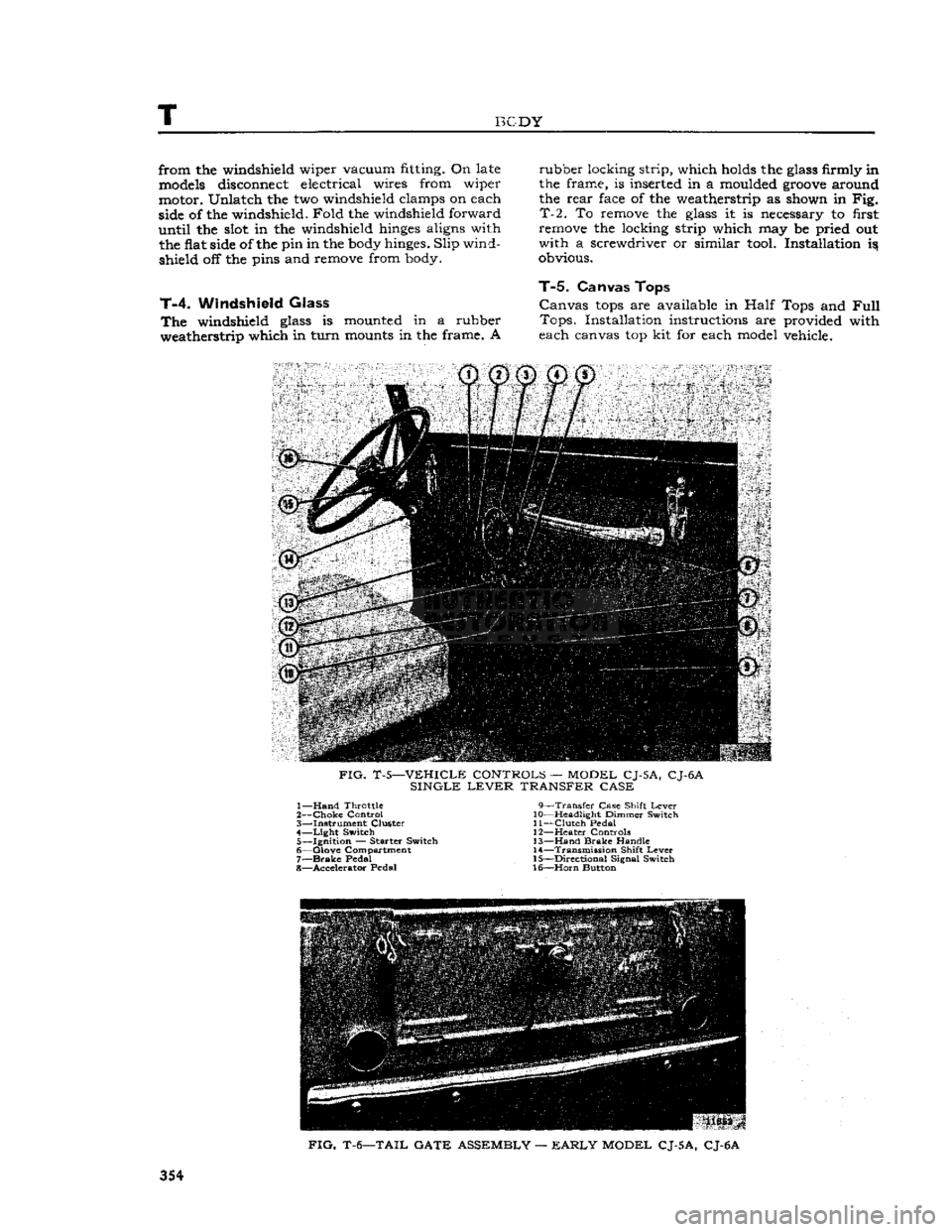
FIG.
T-5—VEHICLE CONTROLS — MODEL CJ-5A, CJ-6A
SINGLE
LEVER
TRANSFER CASE 1—
Hand
Throttle 9—Transfer Case Shift
Lever
2—
Choke
Control 10—Headlight Dimmer Switch
3— Instrument Cluster 11—Clutch Pedal 4—
Light
Switch 12—Heater Controls 5— Ignition — Starter Switch 13—Hand
Brake
Handle
6— Glove Compartment 14—Transmission Shift
Lever
7—
Brake
Pedal 15—Directional Signal Switch
8— Accelerator Pedal 16—Horn Button
FIG.
T-6—TAIL GATE ASSEMBLY —
EARLY
MODEL CJ-5A, CJ-6A
354
Page 357 of 376
'Jeep'
UNIVERSAL SERIES SERVICE
MANUAL
u
MISCEIiLaNEOUS
Contents
SUBJECT
PAR.
Abbreviations
U-15
Extra
Equipment U-2
Front
Bumper Weight U-9
Governor
U-3
Governor
Adjustment U-4
Governor
Maintenance. U-6
U-1. GENERAL
Miscellaneous information included in this sectioi
includes coverage of extra equipment, special
tools,
torque specifications, and charts and tables.
U-2. EXTRA
EQUIPMENT
Much
of the utility of the
*
Jeep*
Universal
is due to
the extra equipment which has been designed to adapt it for farming and industry. The mainte
nance and use of
some
of this equipment is out
lined
in this section.
U-3.
Governor Assembly
The
Novi governor is supplied for models equipped
with
the F4 engine.
This
is a centrifugal type governor and is illustrated in Fig. U-2. Complete
installation
instructions are supplied with each
assembly. Adjustment and operating procedures
are
given below.
U-4.
Governor Adjustment
a.
Adjust the carburetor to obtain smooth
engine
idle at 600 rpm., then
stop
the engine.
b.
Check
throttle linkage to ensure maximum
throttle opening. Be certain that throttle and
governor linkage is free.
c.
Place the carburetor throttle in wide-open posi tion and
pull
the governor control handle out to
the last notch. Adjust the governor to bellcrank
rod
so that the linkage
will
hold the carburetor
throttle in wide-open position.
d.
Close the governor control and start the
engine
Again
pull
the control out to the last notch and
adjust
the length of the cable at adjusting yoke so
that the
engine
will
run at
2600
rpm. Close the
control
to recheck the linkage for free action and
to make sure the
engine
will
return to 600 rpm.
idle speed.
If
the
engine
runs faster than this speed,
loosen
the lock nut which locks the governor hand control
handle on the dash to the rod and back off the
handle until the carburetor idle speed adjusting
screw
bears on the stop. Tighten the lock nut.
In
the absence of electrical tachometer equipment,
engine
speed may be determined by the speedom
eter. Safely
jack
up the
rear
wheels and be sure the front wheel drive is not
engaged.
When driving
the
rear
wheels in high or direct transmission gear,
the
speedometer
will
read from 13j^ to 15 mph. [21.6 to 24.0 kph.] at an
engine
speed of from 900
to 1000 rpm.
SUBJECT
PAR.
Heater
U-10 Miscellaneous Data U-16
Pintle
Hook 1X7
Special
Tools. U-ll
Torque
Specifications U-13, 14, 15
Standard
and Recommended Tools
j.
.U-12
U-5.
Novi Governor Operation /
The
Novi governor is directly belted to the F4
engine
as no clutch is provided to disconnect the
drive.
To
operate the vehicle
WITHOUT
governor con
trol,
push the governor hand control all the way
IN
against the instrument panel.
To
operate the vehicle
WITH
governor control,
pull
the governor hand control handle out. The
hand
control has nine notched positions. Pulling the
control
out to the first notch
sets
the controlled
engine
speed at approximately 1000 rpm. and each successive notch increases the speed 200 rpm.
until
2600
rpm. is reached in the ninth notch. The
hand
control may be released by turning the han dle one-quarter
turn
in either direction.
When
the
engine
is being operated under governor
control
(hand control out) the controlled
engine
speed may be
exceeded
at any time by depressing
the
foot
accelerator in the conventional manner to
secure a greater carburetor throttle opening than
that determined by the governor hand control
setting.
U-6.
Governor Maintenance
The
belt tension may be adjusted by raising or
lowering the governor in the slotted
holes
in the mounting bracket. Keep the pulleys and belt free
of
dirt
and oil. Belt slippage
will
affect governor
operation and a tight belt may cause
rapid
wear
of the governor shaft and bearings. Adjust it to
allow Yi' [12,7 mm.] depression midway
between
the pulleys with thumb pressure.
There
is little wear of the internal parts for they
operate in oil. The governor housings are equipped
with
both
fill
and
drain
plugs and also with level
indicating
plugs.
Check
the oil level at each vehicle
lubrication
and change the oil each time the en
gine
oil is changed using the same grade oil used
in
the engine.
Caution:
Do not
fill
the governor housing above
the level plug. Overfilling
will
prevent governor
control
and possibly cause damage to governor in
ternal
parts. The capacity of
these
governors is two fluid ounces [59,15 cm3]. The filler plug is
also a vent which should be cleaned thoroughly at
each oil change to be sure that the vent operates.
U-7.
Pintle Hook
The
standard type pintle hook, Fig. U-1, affords a
safe, easy hitch for towing a
trailer
or other vehicle. 357
Page 360 of 376
u
MISCELLANEOUS
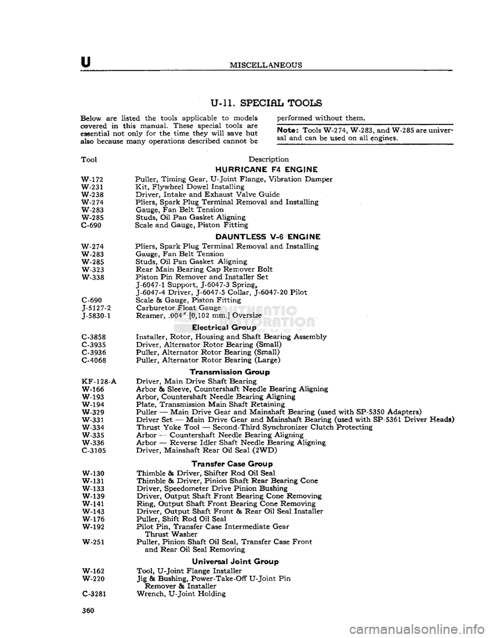
U-ll. SPECIAL TOOLS
Below are listed the
tools
applicable to
models
covered in this manual. These special
tools
are
essential not
only
for the
time
they
will
save
but
also
because
many
operations
described cannot be performed
without
them.
Note;
Tools W-274, W-283, and W-285 are univer
sal
and can be used on all
engines.
Tool
Description
HURRICANE
F4
ENGINE
W-172 Puller, Timing
Gear,
U-Joint Flange, Vibration Damper W-231 Kit, Flywheel Dowel Installing
W-238 Driver, Intake and Exhaust Valve Guide
W-2
74 Pliers, Spark Plug Terminal Removal and Installing W-283 Gauge, Fan Belt Tension W-285 Studs, Oil Pan Gasket Aligning
C-690 Scale and Gauge, Piston Fitting
DAUNTLESS
V-6
ENGINE
W-274 Pliers, Spark Plug Terminal Removal and Installing
W-283 Gauge, Fan Belt Tension W-285 Studs, Oil Pan Gasket Aligning W-323
Rear
Main Bearing Cap Remover Bolt
W-338 Piston Pin Remover and Installer Set
J-6047-1
Support, J-6047-3 Spring,
J-6047-4
Driver, J-6047-5
Collar,
J-6047-20
Pilot
C-690 Scale & Gauge, Piston Fitting
J-5127-2 Carburetor Float Gauge
J-5830-1
Reamer, .004"
[0,102
mm.] Oversize
Electrical
Group
C-3858 Installer, Rotor, Housing and Shaft Bearing Assembly
C-3935 Driver, Alternator Rotor Bearing (Small) C-3936 Puller, Alternator Rotor Bearing (Small)
C-4068 Puller, Alternator Rotor Bearing (Large)
Transmission
Group
KF-128-A
Driver, Main Drive Shaft Bearing W-166 Arbor &
Sleeve,
Countershaft
Needle
Bearing Aligning
W-193 Arbor, Countershaft
Needle
Bearing Aligning W-194 Plate, Transmission Main Shaft Retaining
W-329 Puller — Main Drive
Gear
and Mainshaft Bearing (used with SP-5350 Adapters)
W-331 Driver Set — Main Drive
Gear
and Mainshaft Bearing (used with SP-5361 Driver Heads)
W-334 Thrust Yoke Tool — Second-Third Synchronizer Clutch Protecting W-335 Arbor — Countershaft
Needle
Bearing Aligning
W-336 Arbor — Reverse Idler Shaft
Needle
Bearing Aligning
C-3105 Driver, Mainshaft
Rear
Oil Seal (2WD)
Transfer Case
Group
W-130 Thimble & Driver, Shifter Rod Oil Seal
W-131 Thimble & Driver, Pinion Shaft
Rear
Bearing Cone
W-133 Driver,
Speedometer
Drive Pinion Bushing W-139 Driver, Output Shaft Front Bearing Cone Removing
W-141 Ring, Output Shaft Front Bearing Cone Removing
W-143 Driver, Output Shaft Front &
Rear
Oil Seal Installer W-176 Puller, Shift Rod Oil Seal
W-192 Pilot Pin, Transfer Case Intermediate
Gear
Thrust
Washer
W-251 Puller, Pinion Shaft Oil Seal, Transfer Case Front and
Rear
Oil Seal Removing
Universal
Joint Group
W-162 Tool, U-Joint Flange Installer
W-220 Jig & Bushing, Power-Take-Off U-Joint Pin Remover & Installer
C-3281 Wrench, U-Joint Holding 360
Page 361 of 376
'Jeep*
UNIVERSAL
SERIES
SERVICE
MANUAL
U
DESCRIPTION
—
Continued
AXLES
W-99* Gauge — Pinion & Ring
Gear
Setting
W-104-B* Puller — Tapered Roller Bearing Removing
W-126* Driver — Pinion Bearing Cup
W-128* Installer — Differential Inner Oil Seal W-129 Spreader — Differential
Carrier
Housing
W-138* Driver & Adapter —
King
Pin Bearing
W-144* Wrench — Wheel Bearing Adjusting Nut W-147* Driver — Pinion Oil Seal W-163* Puller
—-
Axle Shaft Drive Flange
W-186* Driver — Axle Shaft Oil Seal
W-188* Driver — Differential Case Bearing W-251* Puller — Pinion Oil Seal
W-262*
Sleeve
— Pinion Bearing Installing
W-263
Semi-Floating
Rear
Axle Shaft Oil Seal W-264* Driver — Pinion Outer Bearing Cup
W-297* Torque Wrench — Pinion Bearing Adjusting W-343* Remover
85
Installer —
Rear
Axle Bearing (Flanged Axle)
W-344* Installer — Pinion Inner Bearing Cups
C-319-A
Puller —
Rear
Wheel Hub (Tapered Axle Shaft)
C-690 Checking Scale —
King
Pin Bearing Preload DD-914-P Press — Tapered Roller Bearing Removing
DD-914-9 Reducer Ring — Differential & Pinion Bearings (Use with DD-914-P)
C-3
716 Driver — Differential
Carrier
Bearing C-4142
Gear
Rotating Tool —
Trac-Lok
Differential
**Jeep*
exclusive
tool
Steering
Group
C-3646 Puller, Steering Shaft Arm
Brake
Group
W-172 Puller, Parking Brake Drum
U-12.
STflNDfiRD
AND
RECOMMENDED
TOOLS
Tool
Description
ENGINE
W-292
Tester — Cooling
System
Thermostat
C-119 Indicator — Cylinder Bore C-385 Compressor — Piston Ring
C-647 Fixture — Spring Testing
C-823
Hone
— Cylinder Bore Refinishing
C-3012 Reamer — Cylinder Ridge
C-3250 Pliers — Radiator fis Heater
Hose
Wire Clamp
C-3411
Gauge — Pressure & Vacuum
C-3422-A Compressor — E-type Valve Spring
C-3501
Hone
— Cylinder
Deglazing
C-3514
Flusher — Cooling
System
C-3886 Fixture — Carburetor Holding C-3896-A Tachometer — Portable
C-3943 Gauge — Compression Checking
C-3952 Torque Wrench, 150
lb-ft.
Swivel Head C-3953 Stand, Engine Repair
C-3959 Light — Ignition Timing
C-4065 Wrench — Oil Filter Removing
C-4080 Tester — Cooling
System
fig
Pressure Cap
ELECTRICAL
40B Hydrometer — Battery Service
W-291 Tester — Instrument
C-3674
Aimers —
Headlight
(Pair)
C-3829 Tester —
Diode
Polarity
C-3888 Tester — Volt-Ampere C-3950 Tester — 12V 60 Amp. Carbon Pile Resistor 361