torque JEEP CJ 1953 Manual PDF
[x] Cancel search | Manufacturer: JEEP, Model Year: 1953, Model line: CJ, Model: JEEP CJ 1953Pages: 376, PDF Size: 19.96 MB
Page 319 of 376
'Jeep*
UNIVERSAL
SERIES SERVICE
MANUAL
D
©—P3
10789
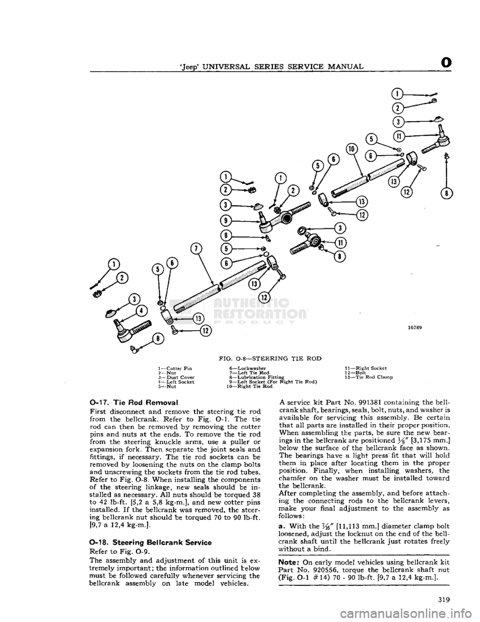
FIG.
0-8—STEERING TIE ROD
1—
Cotter
Pin 6—Lockwasher
2—
Nut 7—Left Tie Rod
3—
Dust
Cover
8—Lubrication
Fitting
4—
Left
Socket 9—Left Socket (For Right Tie Rod) 5— Nut 10—Right Tie Rod 11—
Right
Socket
12—
Bolt
13— Tie
Rod
Clamp
0-17.
Tie Rod
Removal
First
disconnect and remove the steering tie rod
from
the bellcrank. Refer to Fig. O-l. The tie
rod
can then be removed by removing the cotter
pins and
nuts
at the
ends.
To remove the tie rod
from
the steering knuckle arms, use a puller or
expansion
fork.
Then
separate
the
joint
seals
and
fittings,
if
necessary.
The tie rod
sockets
can be
removed by loosening the
nuts
on the clamp bolts
and unscrewing the
sockets
from
the tie rod
tubes.
Refer to Fig. 0-8. When installing the
components
of
the steering linkage, new
seals
should be in stalled as
necessary.
All
nuts
should be torqued 38
to 42
lb-ft.
{5,2 a 5,8
kg-m.],
and new cotter pins
installed.
If the bellcrank was removed, the
steer
ing
bellcrank nut should be torqued 70 to 90
lb-ft.
[9,7
a 12,4
kg-m.].
0-18.
Steering
Bellcrank
Service
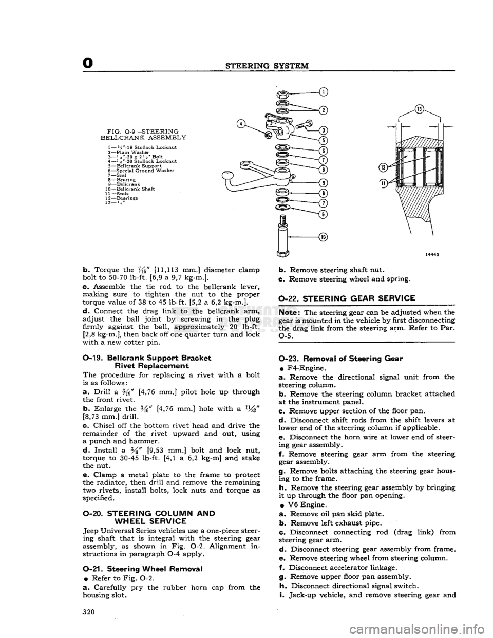
Refer to Fig. 0-9.
The
assembly
and adjustment of this unit is ex
tremely important; the information outlined below must be
followed
carefully whenever servicing the
bellcrank
assembly
on late model vehicles.
A
service kit
Part
No. 991381 containing the
bell
crank shaft, bearings,
seals,
bolt, nuts, and
washer
is
available for servicing this
assembly.
Be certain that all
parts
are installed in their proper position.
When assembling the parts, be
sure
the new
bear
ings in the bellcrank are positioned
Y%"
[3,175 mm.]
below the
surface
of the bellcrank
face
as shown. The
bearings
have
a
light
press"
fit that
will
hold
them in
place
after locating them in the proper
position.
Finally, when installing
washers,
the
chamfer on the
washer
must be installed toward
the bellcrank.
After
completing the
assembly,
and before attach
ing
the connecting
rods
to the bellcrank levers,
make
your
final
adjustment to the
assembly
as
follows:
a.
With
the W [11,113 mm.] diameter clamp bolt
loosened, adjust the locknut on the end of the
bell
crank shaft
until
the bellcrank just
rotates
freely
without
a bind.
Note:
On early model vehicles using bellcrank kit
Part
No. 920556, torque the bellcrank shaft nut
(Fig.
O-l #14) 70 - 90
lb-ft.
[9,7 a 12,4
kg-m.].
319
Page 320 of 376
STEERING
SYSTEM
FIG.
0-9—STEERING
BELLCRANK
ASSEMBLY
1— 5s'-18
Stollock
Lockout
2—
Plain
Washer
3— 7 us"-20
x
2 l2' Bolt
4—
71«
*-20
Stollock
Locknut
5—
Beilcrank
Support
6—
Special
Ground
Washer
7— Seal
8—
Bearing
9— Beilcrank
10— Beilcrank
Shaft
11—
Seals
12—
Bearings
13— } s *
b.
Torque the
Vfc"
[11,113
mm.] diameter elamp
bolt to
50-70
lb-ft. [6,9 a 9,7 kg-m.].
c.
Assemble the tie rod to the beilcrank lever,
making
sure to tighten the nut to the proper
torque value of 38 to 45 lb-ft. [5,2 a 6,2 kg-m.].
d.
Connect the drag
link
to the beilcrank arm,
adjust
the
ball
joint by screwing in the plug firmly against the
ball,
approximately 20 lb-ft. [2,8 kg-m.], then back off one quarter
turn
and lock
with
a new cotter pin.
0-19.
Beilcrank
Support
Bracket
Rivet
Replacement
The
procedure for replacing a rivet with a bolt
is as follows:
a.
Drill
a [4,76 mm.] pilot
hole
up through
the front rivet.
b.
Enlarge
the [4,76 mm.]
hole
with a %"
[8,73 mm.]
drill.
c.
Chisel
off the
bottom
rivet head and drive the
remainder
of the rivet upward and out, using
a
punch and hammer.
d.
Install
a %" [9,53 mm.] bolt and lock nut,
torque to
30-45
lb-ft. [4,1 a 6,2 kg-m] and stake
the nut.
e.
Clamp
a metal plate to the frame to protect
the radiator, then
drill
and remove the remaining two rivets, install bolts, lock nuts and torque as
specified.
O-20.
STEERING
COLUMN
AND
WHEEL SERVICE
Jeep
Universal
Series vehicles use a
one-piece
steer
ing
shaft that is integral with the steering gear
assembly, as shown in Fig. 0-2. Alignment in
structions in paragraph 0-4 apply.
0-21.
Steering
Wheel Removal •
Refer to Fig. 0-2.
a.
Carefully
pry the rubber horn cap from the housing slot.
b.
Remove steering shaft nut.
c.
Remove steering wheel and spring.
0-22.
STEERING GEAR SERVICE
Note:
The steering gear can be adjusted when the
gear is mounted in the vehicle by first disconnecting
the drag
link
from the steering arm. Refer to Par.
Q-5.
0-23.
Removal
of
Steering Gear
•
F4-Engine.
a.
Remove the directional signal unit from the steering column.
b.
Remove the steering column bracket attached
at the instrument panel.
c.
Remove upper section of the floor pan.
d.
Disconnect shift rods from the shift levers at
lower end of the steering column if applicable.
e.
Disconnect the horn wire at lower end of steer
ing
gear assembly.
f.
Remove steering gear arm from the steering gear assembly.
g.
Remove
bolts
attaching the steering gear hous
ing
to the frame.
h.
Remove the steering gear assembly by bringing
it
up through the floor pan opening.
•
V6 Engine.
a.
Remove oil pan
skid
plate.
b.
Remove
left
exhaust pipe.
c.
Disconnect connecting rod (drag
link)
from
steering gear arm.
d.
Disconnect steering gear assembly from frame.
e.
Remove steering wheel from steering column.
f. Disconnect accelerator linkage.
g.
Remove upper floor pan assembly.
h.
Disconnect directional signal switch.
i.
Jack-up
vehicle, and remove steering gear and
320
Page 321 of 376
'Jeep'
UNIVERSAL
SERIES SERVICE
MANUAL
O
column assembly down through the floor pan open
ing and out from under vehicle.
0-24.
Disassembly
of
Steering
Gear
Refer
to Fig. 0-2.
When
the steering gear arm is installed on early
production vehicles, the line across the face of the
arm
and the end of the shaft should be in align ment. On later production vehicles, blind splines
on the lever shaft and in the steering gear arm en
sure
correct positioning of the arm.
a.
Remove the steering gear arm with a puller
C-3646.
Caution:
Do not use a hammer or
wedge
to re
move
the steering arm from the shaft and lever.
This
can cause damage to the shaft assembly.
b.
Loosen the lock nut and unscrew the adjusting
screw
two turns.
c.
Remove the side cover screws and washers. Re
move
the side cover and gasket.
d.
Remove lever shaft.
e.
Remove upper cover plate screws. Remove cam,
wheel tube, and bearing assembly from the housing.
f.
Clean
all parts with suitable cleaning solvent and wipe dry.
g.
After dismantling as outlined above is com
pleted, inspect cam
grooves
for wear, chipping and
scoring,
also the
ball
races on the cam ends and the
separate
ball
cups. Existence of any of
these
condi tions indicates the necessity for parts replacement.
h.
Inspect the tapered stud mounted on the lever
shaft for flat
spots
and chipping. In the case of
either, replacement is usually advisable. Inspect the
lever shaft for wear and
test
the fit of the shaft in
the bushings.
i.
Inspect condition of the oil seal at outer end of
lever shaft and the bearing at top end of steering
column.
0-25.
Reassembly
of
Steering
Gear
e Refer to Fig. 0-2.
Reassemble all parts to wheel tube in reverse order
of dismantling. Assemble cam, wheel tube and
bearing
assembly in housing, seating the lower
bearing
ball
cup in the housing.
Note:
New plastic retainer type cam bearings are
now available for the Ross steering gears. The new
bearings replace, and are interchangeable with,
the lock ring type cam bearings on gears equipped
with
early type cams.
With
adjusting shims in place, assemble upper
cover and adjust the cam bearings.
Assemble lever shaft in housing and with gasket
in
place assemble the side cover and set adjusting
screw
for a minimum backlash of the studs in the
cam
groove, with the steering gear at the center
point of travel.
When
assembling upper bearing spring and spring
seat in jacket tube make sure that the spring seat
is positioned correctly. It must be installed with
the lengthwise flange down against the bearing and
not up inside of spring coil.
0-26.
Installation
of
Steering
Gear
a.
After the gear has been properly adjusted, as
outlined in Par. 0-5, install steering gear assembly
in
chassis in the reverse order in which it was re
moved.
b.
After installing the assembly in the vehicle,
jack
up front of vehicle and place the front wheels
in
the straight ahead position.
c.
Temporarily install the steering wheel to locate
the mid-position of the steering gear. To locate the mid-position,
turn
the steering wheel as far to the
right
as possible and then
turn
in the
opposite
di
rection
as far as possible, noting the total number
of turns.
Turn
the wheel back just ^ of the total movement to place the gear in mid-position.
d.
With
the steering gear in mid-position and the
wheels in the straight ahead position install steer ing gear arm on lever shaft with the
ball
end down.
When
installed the line across the face of the arm
and
end of shaft should be in alignment.
0-27.
Steering
Wheel
Installation
•
Refer to Fig. 0-2.
a.
Install
steering wheel and spring on shaft.
Align
scribe marks on shaft and hub of wheel.
b.
Install
steering shaft nut and torque 20 to 25
lb-ft. [2,8 a 3,4 kg-m.].
c.
Install
horn cap. Test horn.
321
Page 338 of 376
Q
WHEELS
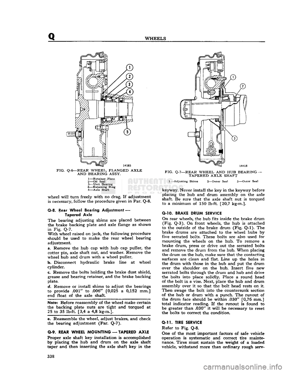
FIG.
Q-6—REAR
WHEEL,
FLANGED
AXLE
AND
BEARING
ASSY.
1—
Retainer
Plate
2— Oil
Seal
3—
Unit
Bearing
4—
Retaining
Ring
5—
Axle
Shaft
wheel
will
turn
freely with no drag. If adjustment
is necessary, follow the procedure given in Par. Q-8.
Q-8.
Rear Wheel Bearing Adjustment
—
Tapered Axle
The
bearing adjusting shims are placed
between
the brake backing plate and axle flange as shown
in
Fig. Q-7.
With
wheel raised on
jack,
the following procedure
should be used to make the
rear
wheel bearing
adjustment.
a.
Remove the hub cap with hub cap puller, the
cotter pin, axle shaft nut, and washer. Remove the
wheel hub and drum with a wheel puller.
b.
Disconnect hydraulic brake line at wheel
cylinder.
c.
Remove the
bolts
holding the brake dust shield, grease and bearing retainer, and the brake backing
plate.
d.
Remove or install shims to adjust the bearings
to provide .001" to .006" [0,025 a 0,152 mm.]
end float of the axle shaft.
Note:
Before reassembly of the wheel make certain
the backing plate nuts are tight and torqued at 25 to 35 lb-ft [3,4 a 4,8 kg-m.].
e. Reassemble the wheel, adjust brakes, and check
the bearing adjustment (Par. Q-7).
0-9.
REAR WHEEL MOUNTING
—
TAPERED AXLE
Proper
axle shaft key installation is accomplished by placing the hub and drum on the axle shaft
taper and then inserting the axle shaft key in the
FIG.
Q-7—REAR
WHEEL
AND HUB
BEARING
—
TAPERED
AXLE
SHAFT
1—-Adjusting
Shims
2—Inner
Seal
3—Outer
Seal
keyway.
Never install the key in the keyway before
placing
the hub and drum assembly on the axle
shaft. Be sure that the axle shaft nut is torqued
to a minimum of 150 lb-ft. [20,7 kg-m.].
O-10.
BRAKE
DRUM
SERVICE
On
rear
wheels, the hub fits inside the brake drum
(Fig.
Q-3). On front wheels, the hub is attached
to the outside of the brake drum (Fig. Q-l). The
brake
drums are attached to the wheel hubs by
five serrated bolts. These
bolts
are also used for
mounting the wheels on the hub. To remove a
brake
drum,
press or drive out the serrated
bolts
and
remove the drum from the hub. When placing
the drum on the hub, make sure that the contacting
surfaces are clean and flat.
Line
up the
holes
in
the drum with
those
in the hub and put the drum
over the shoulder on the hub. Insert five new
serrated
bolts
through the drum and hub and drive
the
bolts
into place solidly. Place a round head of the bolt in a vise. Next, place the hub and drum
assembly over it so that the bolt head rests on it.
Then
swage
the bolt into the countersunk section of the hub or drum with a punch. The runout of
the drum face should be within .030" [0,76 mm.]
total indicator reading. If the runout is found to be greater than .030" it
will
be necessary to reset
the
bolts
to correct the condition.
0-11.
TIRE SERVICE
Refer
to Fig. Q-8.
One
of the most important factors of safe vehicle
operation is systematic and correct tire mainte nance.
Tires
must sustain the weight of a loaded vehicle, withstand more than ordinary rough serv- 338
Page 340 of 376
Q
WHEELS
11463
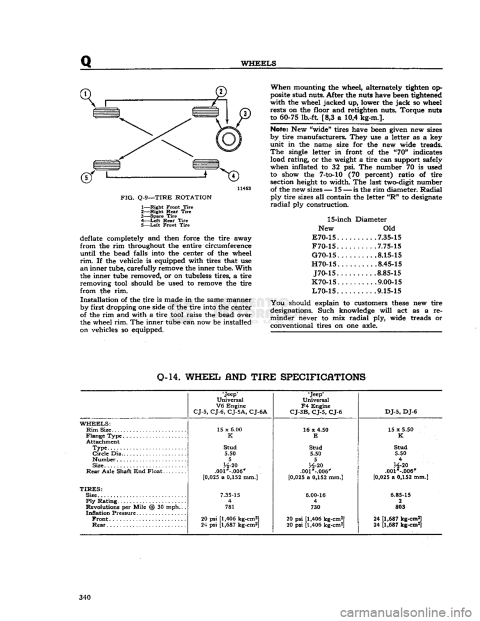
FIG.
Q-9—TIRE
ROTATION
1—
Right
Front
Tire
2—
Right
Rear
Tire
3—
Spare
Tire
4—
-Left
Rear
Tire
5—
Left
Front
Tire
deflate completely and then force the tire away
from
the rim throughout the entire circumference
until
the bead falls into the center of the wheel
rim.
If the vehicle is equipped with tires that use
an
inner tube, carefully remove the inner tube.
With
the inner tube removed, or on tubeless tires, a tire
removing tool should be used to remove the tire
from
the rim.
Installation
of the tire is made in the same manner
by first dropping one side of the tire into the center
of the rim and with a tire tool raise the bead over
the wheel
rim.
The inner tube can now be installed
on vehicles so equipped.
When
mounting the wheel, alternately tighten op
posite stud nuts. After the nuts have been tightened
with
the wheel jacked up, lower the
jack
so wheel rests on the floor and retighten nuts. Torque nuts
to 60-75 lb.-ft. [8,3 a 10,4 kg-m.].
Note:
New "wide" tires have been given new sizes
by tire manufacturers. They use a letter as a key
unit
in the name size for the new wide treads.
The
single letter in front of the "70" indicates load rating, or the weight a tire can support safely
when inflated to 32 psi. The number 70 is used to show the
7-to-10
(70 percent) ratio of tire section height to width. The last two-digit number of the new sizes— 15 —
is
the rim diameter.
Radial
ply
tire sizes all contain the letter
"R"
to designate
radial
ply construction.
15-inch
Diameter
New Old
E70-15
7.35-15
F70-15
.7.75-15
G70-15
8.15-15
H70-15
8.45-15
J70-15
.8.85-15
K70-15
. .... .9.00-15
L70-15
9.15-15
You
should explain to customers
these
new tire
designations. Such knowledge
will
act as a re
minder
never to mix
radial
ply, wide treads or
conventional tires on one axle.
0-14.
WHEEL
AND
TIRE
SPECIFICATIONS
'Jeep'
Universal
V6
Engine
CJ-5,
CJ-6,
CJ-5A,
CJ-6A
'Jeep*
Universal
F4
Engine
CJ-3B,
CJ-5,
CJ-6
DJ-5,
DJ-6
WHEELS:
Rim
Size 15 x
6.00
16 x 4.50
15 x 5.50
K
E
K
Attachment
Type
Stud
Stud Stud
Circle
Dia 5.50 5.50 5.50
5 5
4
Size
H-20
H-20
H-20
Rear
Axle Shaft End Float .001*-.006"
.001"-.006" .001 *-.006"
[0 ,025 a 0,152 mm.)
[0,025 a 0,152 mm.] [0,025 a 0,152 mm.]
TIRES:
Size.
7.35-15
6.00-16
6.85-15
Ply
Rating 4
4 2
Revolutions per Mile @ 30 mph.. . 781 730 803
Inflation
Pressure
Front
20
psi
[1,406 kg-cm2]
20 psi [1,406 kg-cm2] 24 [1,687 kg-cm*]
Rear
24
psi
[1,687 kg-cm*]
20 psi [1,406 kg-cm2] 24 [1,687 kg-cm*] 340
Page 345 of 376
'Jeep'
UNIVERSAL
SERIES
SERVICE
MANUAL
s
SPRINGS
AND
SHOCK
ABSORBERS
Contents
SUBJECT
PAR. SUBJECT PAR.
Pivot Bolts S-3 Spring Removal S-4
Shock
Absorbers S-7 Spring Shackles S-2
Spring
Installation S-5 U-Shackles S-6
S-1.
GENERAL
Semielliptical
leaf springs are used for all models.
The
springs are hung longitudinally from the frame
side rails by means of brackets welded to the
rails.
All
axles are firmly attached to the springs by U-
bolts
(spring clips), spring saddles welded to the
underside of the axles, and spring plates under the
springs.
Early
model DJ-5 and DJ-6 front axles (I beam) are attached to the springs with conven
tional
bolts
and spring plates. Spring center
bolts
are
inserted in the axle spring saddles to prevent
shifting of the axle.
All
front springs, except as noted below, are provided with shackles at the front ends of the springs
and
pivot
bolts
at the
rear
ends of the springs. Model CJ-5 up to
Serial
No. 44437 and Model
CJ-6
up to
Serial
No. 11981 are provided with shackles at the
rear
ends of the front springs, and
pivot
bolts
at the front ends.
Note:
Models
CJ-5A
and
CJ-6A
are equipped with
the two
stage
type front and
rear
spring.
All
rear
springs are provided with shackles at the
rear
end and pivot
bolts
at the front end.
Springs
should be examined periodically for broken
or
shifted leaves,
loose
or missing rebound clips,
angle of spring shackles, and position of springs
on the saddles. Springs with shifted leaves do not have their normal strength. Missing rebound clips may permit the spring leaves to fan out or break
on rebound. Broken leaves may make the vehicle
hard
to handle or permit the axle to shift out of
line.
Weakened springs may break causing difficulty
in
steering. Spring attaching clips or
bolts
must be tight. It is
suggested
that they be checked at each
vehicle inspection and torqued 45 to 55 lb-ft. [6,2 a 7,6 kg-m.].
S-2.
Spring Shackles
Rubber-bushed
shackles are provided on all current
production vehicles. The steel-backed rubber (silent bloc) bushings are pressed into the spring
eyes
and mounting brackets. The shackle
bolts
tighten the side plates against the inner steel back
ing of the bushings. Oscillation of the springs is
taken in the rubber bushings.
All
vehicles produced before early 1957 were
equipped with U-shackles and threaded core bush-
*3(
21-
to It is
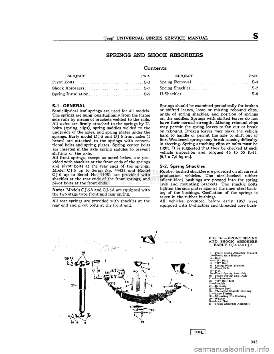
FIG-
S-1—FRONT SPRING
AND SHOCK ABSORBER
EARLY
CJ-5 and CJ-6
1—
Front
Shock Absorber
Bracket
2—
Front
Axle
Bumper
3—
Bolt
4—
"U"
Bolt
5—
"U"
Bolt
6—
Spring
Pivot
Bracket
7—
Pivot
Bolt
8—
Nut
9—
Front
Spring
Assembly
10—Front
Spring
Clip
Plate
11
—Lockwasher
12—
"U"
Bolt Nut
13—
Shackle
14—
Retainer
15—
Grease
Seal
16—
Threaded
Shackle
Bushing
17—
Lube
Fitting
18—
Mounting
Pin Bushing
19—
Washer
20—
Lock
Nut
21—
Shock
Absorber Assembly
1190L
345
Page 346 of 376
SPRINGS
AND
SHOCK
ABSORBERS
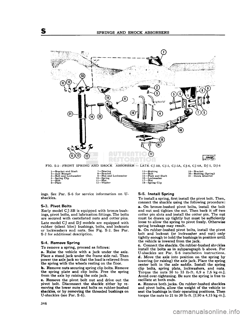
FIG.
S-2—FRONT
SPRING
AND
SHOCK
ABSORBER
—
LATE
CJ-3B,
CJ-5,
CJ-5A,
CJ-6,
CJ-6
A,
DJ-5, DJ-6 1—
Bracket
and Shaft
2—
Axle
Bumper
3—
Bolt
and
Lockwasher
4—
Spring
Clip
5—
Bolt
6—
Plate
7—
Bearing
8—
Bracket
9—
Nut
and
Lockwasher
10—
Spring
11—
Nut
12—
Washer
13—
Bushing
14—
Bolt
15—
Plate
and Shaft
16—
Lockwasher
17—
Nut
18—
Spring
Clip
19—
Bracket
20—
Bushing
(Spring)
21—
Shock
Absorber ings. See Par.
shackles.
S-6 for service information on U-
S-3.
Pivot
Bolts
Early
model
CJ-3B
is equipped with bronze bush
ings, pivot bolts, and lubrication fittings. The
bolts
are
secured with castellated nuts and cotter pins.
Late
model
CJ
and DJ models are equipped with
rubber
(silent bloc) bushings, bolts, and locknuts
or
lockwashers and nuts. See Fig. S-2. See Par. S-2 for additional description.
S-4.
Remove
Spring
To
remove a spring, proceed as follows:
a.
Raise
the vehicle with a
jack
under the axle.
Place
a stand
jack
under the frame side
rail.
Then
power the axle
jack
so that the load is relieved from the spring with the wheels resting on the floor.
b.
Remove nuts securing spring clip bolts. Remove
the spring plate and clip bolts.
Free
the spring
from
the axle by raising the axle
jack.
C.
Remove the pivot bolt nut and drive out the pivot bolt. Disconnect the shackle either by removing the lower nuts and
bolts
on rubber-bushed
shackles,
or by removing the threaded bushings on
U-shackles
(see Par. S-6).
S-5.
Install
Spring
To
install a
spring,
first install the pivot bolt.
Then,,
connect the shackle using the following procedure:
a.
On bronze-bushed pivot bolts, install the bolt
and
nut and tighten the nut.
Then
back it off two
cotter pin
slots
and install the cotter pin. The nut must be
drawn
up tightly but must be sufficiently
loose
to allow the spring to pivot freely. Otherwise
spring
breakage may result.
b.
On rubber-bushed pivot bolts, install the pivot
bolt and locknut (or lockwasher and nut) only
tightly enough to hold the bushings in position until
the vehicle is lowered from the
jack.
c.
Connect the shackle. On
rubber-bushed
shpckles
install
the
bolts
as in subparagraph b above. For
U-shackles
see Par. S-6 installation instructions.
d.
Move the axle into position on the spring by
lowering
(or raising) the axle
jack.
Place the spring, center bolt in the axle saddle.
Install
the spring
clip
bolts, spring plate, lockwashers, and nuts.
Torque
the nuts 50 to 55 lb-ft. 6,9 a 7,6 kg-m.].
Avoid
over-tightening. Be sure the spring is free to
oscillate at both ends.
e. Remove both
jacks.
On rubber-bushed shackles
and
pivot bolts, allow the weight of the vehicle to
seat the bushings in their operating positions.
Then
torque the nuts to 21 to 30 lb-ft. [2,90 a 4,15 kg-m.]. 346
Page 357 of 376
'Jeep'
UNIVERSAL SERIES SERVICE
MANUAL
u
MISCEIiLaNEOUS
Contents
SUBJECT
PAR.
Abbreviations
U-15
Extra
Equipment U-2
Front
Bumper Weight U-9
Governor
U-3
Governor
Adjustment U-4
Governor
Maintenance. U-6
U-1. GENERAL
Miscellaneous information included in this sectioi
includes coverage of extra equipment, special
tools,
torque specifications, and charts and tables.
U-2. EXTRA
EQUIPMENT
Much
of the utility of the
*
Jeep*
Universal
is due to
the extra equipment which has been designed to adapt it for farming and industry. The mainte
nance and use of
some
of this equipment is out
lined
in this section.
U-3.
Governor Assembly
The
Novi governor is supplied for models equipped
with
the F4 engine.
This
is a centrifugal type governor and is illustrated in Fig. U-2. Complete
installation
instructions are supplied with each
assembly. Adjustment and operating procedures
are
given below.
U-4.
Governor Adjustment
a.
Adjust the carburetor to obtain smooth
engine
idle at 600 rpm., then
stop
the engine.
b.
Check
throttle linkage to ensure maximum
throttle opening. Be certain that throttle and
governor linkage is free.
c.
Place the carburetor throttle in wide-open posi tion and
pull
the governor control handle out to
the last notch. Adjust the governor to bellcrank
rod
so that the linkage
will
hold the carburetor
throttle in wide-open position.
d.
Close the governor control and start the
engine
Again
pull
the control out to the last notch and
adjust
the length of the cable at adjusting yoke so
that the
engine
will
run at
2600
rpm. Close the
control
to recheck the linkage for free action and
to make sure the
engine
will
return to 600 rpm.
idle speed.
If
the
engine
runs faster than this speed,
loosen
the lock nut which locks the governor hand control
handle on the dash to the rod and back off the
handle until the carburetor idle speed adjusting
screw
bears on the stop. Tighten the lock nut.
In
the absence of electrical tachometer equipment,
engine
speed may be determined by the speedom
eter. Safely
jack
up the
rear
wheels and be sure the front wheel drive is not
engaged.
When driving
the
rear
wheels in high or direct transmission gear,
the
speedometer
will
read from 13j^ to 15 mph. [21.6 to 24.0 kph.] at an
engine
speed of from 900
to 1000 rpm.
SUBJECT
PAR.
Heater
U-10 Miscellaneous Data U-16
Pintle
Hook 1X7
Special
Tools. U-ll
Torque
Specifications U-13, 14, 15
Standard
and Recommended Tools
j.
.U-12
U-5.
Novi Governor Operation /
The
Novi governor is directly belted to the F4
engine
as no clutch is provided to disconnect the
drive.
To
operate the vehicle
WITHOUT
governor con
trol,
push the governor hand control all the way
IN
against the instrument panel.
To
operate the vehicle
WITH
governor control,
pull
the governor hand control handle out. The
hand
control has nine notched positions. Pulling the
control
out to the first notch
sets
the controlled
engine
speed at approximately 1000 rpm. and each successive notch increases the speed 200 rpm.
until
2600
rpm. is reached in the ninth notch. The
hand
control may be released by turning the han dle one-quarter
turn
in either direction.
When
the
engine
is being operated under governor
control
(hand control out) the controlled
engine
speed may be
exceeded
at any time by depressing
the
foot
accelerator in the conventional manner to
secure a greater carburetor throttle opening than
that determined by the governor hand control
setting.
U-6.
Governor Maintenance
The
belt tension may be adjusted by raising or
lowering the governor in the slotted
holes
in the mounting bracket. Keep the pulleys and belt free
of
dirt
and oil. Belt slippage
will
affect governor
operation and a tight belt may cause
rapid
wear
of the governor shaft and bearings. Adjust it to
allow Yi' [12,7 mm.] depression midway
between
the pulleys with thumb pressure.
There
is little wear of the internal parts for they
operate in oil. The governor housings are equipped
with
both
fill
and
drain
plugs and also with level
indicating
plugs.
Check
the oil level at each vehicle
lubrication
and change the oil each time the en
gine
oil is changed using the same grade oil used
in
the engine.
Caution:
Do not
fill
the governor housing above
the level plug. Overfilling
will
prevent governor
control
and possibly cause damage to governor in
ternal
parts. The capacity of
these
governors is two fluid ounces [59,15 cm3]. The filler plug is
also a vent which should be cleaned thoroughly at
each oil change to be sure that the vent operates.
U-7.
Pintle Hook
The
standard type pintle hook, Fig. U-1, affords a
safe, easy hitch for towing a
trailer
or other vehicle. 357
Page 361 of 376
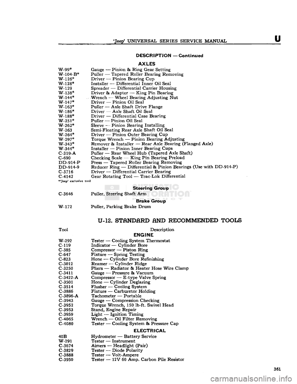
'Jeep*
UNIVERSAL
SERIES
SERVICE
MANUAL
U
DESCRIPTION
—
Continued
AXLES
W-99* Gauge — Pinion & Ring
Gear
Setting
W-104-B* Puller — Tapered Roller Bearing Removing
W-126* Driver — Pinion Bearing Cup
W-128* Installer — Differential Inner Oil Seal W-129 Spreader — Differential
Carrier
Housing
W-138* Driver & Adapter —
King
Pin Bearing
W-144* Wrench — Wheel Bearing Adjusting Nut W-147* Driver — Pinion Oil Seal W-163* Puller
—-
Axle Shaft Drive Flange
W-186* Driver — Axle Shaft Oil Seal
W-188* Driver — Differential Case Bearing W-251* Puller — Pinion Oil Seal
W-262*
Sleeve
— Pinion Bearing Installing
W-263
Semi-Floating
Rear
Axle Shaft Oil Seal W-264* Driver — Pinion Outer Bearing Cup
W-297* Torque Wrench — Pinion Bearing Adjusting W-343* Remover
85
Installer —
Rear
Axle Bearing (Flanged Axle)
W-344* Installer — Pinion Inner Bearing Cups
C-319-A
Puller —
Rear
Wheel Hub (Tapered Axle Shaft)
C-690 Checking Scale —
King
Pin Bearing Preload DD-914-P Press — Tapered Roller Bearing Removing
DD-914-9 Reducer Ring — Differential & Pinion Bearings (Use with DD-914-P)
C-3
716 Driver — Differential
Carrier
Bearing C-4142
Gear
Rotating Tool —
Trac-Lok
Differential
**Jeep*
exclusive
tool
Steering
Group
C-3646 Puller, Steering Shaft Arm
Brake
Group
W-172 Puller, Parking Brake Drum
U-12.
STflNDfiRD
AND
RECOMMENDED
TOOLS
Tool
Description
ENGINE
W-292
Tester — Cooling
System
Thermostat
C-119 Indicator — Cylinder Bore C-385 Compressor — Piston Ring
C-647 Fixture — Spring Testing
C-823
Hone
— Cylinder Bore Refinishing
C-3012 Reamer — Cylinder Ridge
C-3250 Pliers — Radiator fis Heater
Hose
Wire Clamp
C-3411
Gauge — Pressure & Vacuum
C-3422-A Compressor — E-type Valve Spring
C-3501
Hone
— Cylinder
Deglazing
C-3514
Flusher — Cooling
System
C-3886 Fixture — Carburetor Holding C-3896-A Tachometer — Portable
C-3943 Gauge — Compression Checking
C-3952 Torque Wrench, 150
lb-ft.
Swivel Head C-3953 Stand, Engine Repair
C-3959 Light — Ignition Timing
C-4065 Wrench — Oil Filter Removing
C-4080 Tester — Cooling
System
fig
Pressure Cap
ELECTRICAL
40B Hydrometer — Battery Service
W-291 Tester — Instrument
C-3674
Aimers —
Headlight
(Pair)
C-3829 Tester —
Diode
Polarity
C-3888 Tester — Volt-Ampere C-3950 Tester — 12V 60 Amp. Carbon Pile Resistor 361
Page 362 of 376
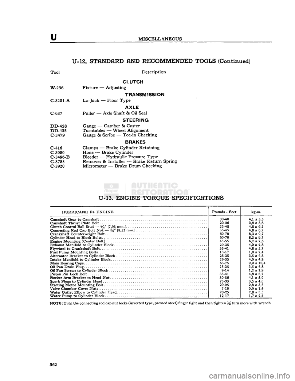
u
MISCELLANEOUS
U-12.
STANDARD
AND
RECOMMENDED TOOLS
(Continued)
Tool
Description
CLUTCH
W-296 Fixture — Adjusting
TRANSMISSION
C-3201
- A
Lo-Jack
— Floor Type
AXLE
C-637 Puller — Axle Shaft & Oil Seal
STEERING
DD-428 Gauge — Camber & Caster
DD-435 Turntables — Wheel Alignment C-3479 Gauge & Scribe — Toe-in Checking
BRAKES
C-416 Clamps — Brake Cylinder Retaining C-3080 Hone — Brake Cylinder
C-3496-B Bleeder — Hydraulic Pressure Type C-3785 Remover & Installer — Brake Return Spring
C-3920 Micrometer — Brake Drum Checking
U-13.
ENGINE TORQUE SPECIFICATIONS HURRICANE
F4
ENGINE
Pounds - Feet
kg-m.
30-40
4,1
a
5,5
Camshaft
Thrust Plate Bolt
20-26
2,8
a
3,6
Clutch
Control
Ball
Stud — [7,93 mm.]
35-45
4,8
a
6,2
Connecting Rod Cap Bolt Nut — y8" [9,53 mm.|
35-45
4,8
a
6,2
60-70
8,3
a
9,7
Cylinder
Head to Block Bolts
60-70
8,3
a
9,7
45-55
6,2
a
7,6
29-35
4,0
a
4,8
Flywheel
to Crankshaft Bolt. 35-41
4,8
a
5,7
Fuel
Pump Mounting Bolts 13-17 1,8
a
2,4
Alternator Bracket to Cylinder Block.
25-35
3,5
a
4,8
29-35
4,0
a
4,8
Main
Bearing
Caps.
.
65-75
9,0
a
10,4
Oil
Pan
Drain
Plug
25-35
3,5
a
4,8
9-14 1,2
a
1,9
Piston Pin
Lock
Bolt 35-41
4,8
a
5,7
30-36
4,1
a
5,0
Spark
Plugs to Cylinder Head
25-33
3,5
a
4,6
Starting Motor Mounting Bolt.
20-25
2,8
a
3,5
7-10 0,9
a
1,4
Water
Outlet Elbow to Cylinder Head
20-25
2,8
a
3,5
Water
Pump to Cylinder Block 12-17
1,7
a
2,4
NOTE:
Turn
the connecting rod cap nut locks (inverted type, pressed
steel)
finger
tight
and then
tighten
% turn more with wrench
362