torque JEEP CJ 1953 Workshop Manual
[x] Cancel search | Manufacturer: JEEP, Model Year: 1953, Model line: CJ, Model: JEEP CJ 1953Pages: 376, PDF Size: 19.96 MB
Page 237 of 376
'Jeep'
UNIVERSAL
SERIES
SERVICE
MANUAL
I
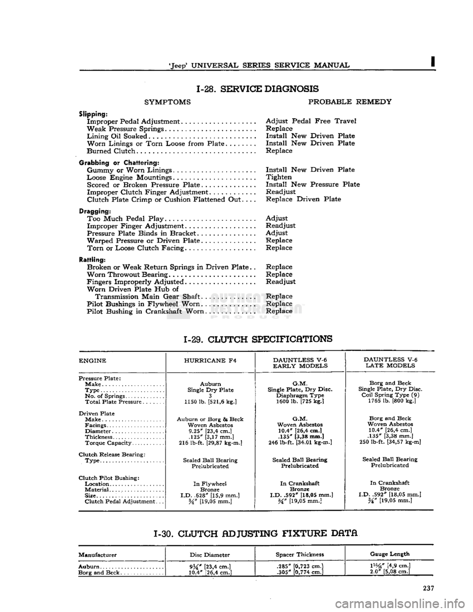
1-28.
SERVICE
DIAGNOSIS
SYMPTOMS
PROBABLE
REMEDY
Slipping:
Improper Pedal Adjustment Adjust Pedal Free
Travel
Weak Pressure Springs Replace
Lining
Oil Soaked Install New Driven Plate
Worn
Linings or
Torn
Loose from Plate Install New Driven Plate
Burned Clutch Replace
Grabbing
or
Chattering:
Gummy or Worn Linings Install New Driven Plate
Loose Engine
Mountings
Tighten Scored or Broken Pressure Plate Install New Pressure Plate
Improper Clutch Finger Adjustment............ Readjust
Clutch
Plate Crimp or Cushion Flattened Out.... Replace Driven Plate
Dragging: Too Much Pedal Play. Adjust Improper Finger Adjustment. Readjust
Pressure Plate Binds in Bracket Adjust
Warped Pressure or Driven Plate Replace
Torn
or Loose Clutch Facing. Replace
Rattling:
Broken or Weak Return Springs in Driven Plate.. Replace
Worn
Throwout Bearing Replace
Fingers Improperly Adjusted Readjust
Worn
Driven Plate Hub of Transmission Main Gear Shaft.............. Replace
Pilot Bushings in Flywheel Worn.
.............
Replace
Pilot Bushing in Crankshaft Worn Replace
1-29.
CLUTCH
SPECIFICATIONS
ENGINE
HURRICANE
F4
DAUNTLESS
V-6
DAUNTLESS
V-6
EARLY
MODELS
LATE
MODELS
Pressure Plate;
Auburn
G.M.
Borg and Beck
Type
Single
Dry Plate
Single
Plate, Dry Disc.
Single
Plate, Dry Disc.
No. of Springs 3 Diaphragm Type
Coil
Spring Type (9)
Total
Plate Pressure 1150 lb.
[521,6
kg.]
1600 lb. [725 kg.] 1765 lb. [800 kg.]
Driven Plate Make
Auburn
or Borg & Beck
G.M.
Borg and Beck
Facings Woven
Asbestos
Woven
Asbestos
Woven
Asbestos
Diameter 9.25" [23,4 cm.] 10.4" [26,4 cm.]
10.4" [26,4 cm.]
Thickness .125" [3,17 mm.] .135" [3,38 mm.]
.135" [3,38 mm.]
Torque Capacity 216 lb-ft.
[29,87
kg-m.]
246 lb-ft.
[34.01
kg-m.]
250 lb-ft.
[34,57
kg-m]
Clutch
Release Bearing: Sealed
Ball
Bearing
.
Type Sealed
Ball
Bearing Sealed
Ball
Bearing Sealed
Ball
Bearing
.
Type
Prelubricated Prelubricated
Prelubricated
Clutch
Pilot Bushing:
In
Crankshaft
In
Flywheel
In
Crankshaft
In
Crankshaft
Material
Bronze Bronze
Bronze
Size.
I.D.
.628" [15,9 mm.]
I.D.
.592"
[18,05
mm.]
I.D.
.592"
[18,05
mm.]
Clutch
Pedal Adjustment. .. W
[19,05
mm.]
%n
[19,05
mm.]
%n
[19,05
mm.]
1-30.
CLUTCH
ADJUSTING
FIXTURE
DATA
Manufacturer Disc Diameter Spacer Thickness Gauge Length
Auburn
9j£"
[23,4 cm.]
10.4" [26,4 cm.] .285"
.305"
0,723
cm.]
0,774
cm.]
mtf
[4,9 cm.]
2.0" [5,08 cm.]
9j£"
[23,4 cm.]
10.4" [26,4 cm.] .285"
.305"
0,723
cm.]
0,774
cm.]
mtf
[4,9 cm.]
2.0" [5,08 cm.]
Page 256 of 376
THREE-SPEED
TRANSMISSION
ing
snap
ring.
Care should be taken to
install
the
proper
snap
ring
at
these
locations.
fl.
Install
the mainshaft rear bearing
adapter,
spacer,
transfer
case
drive
gear,
flat
washer, and
nut.
Torque nut 130 to 170
lb-ft.
[17,9 a 23,5
kg-m.].
Refer to Fig. J-15.
o. Check the main drive bearing retainer oil seal.
If
seal is
worn
or damaged it must be replaced.
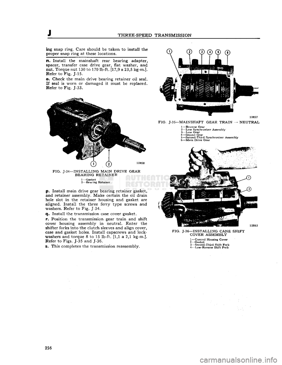
Refer to Fig. J-33. 12858
FIG.
J-34—INSTALLING
MAIN
DRIVE GEAR BEARING RETAINER
-Gasket
-Bearing
Retainer
p.
Install
main drive
gear
bearing retainer gasket,
and retainer assembly. Make certain the oil drain
hole
slot in the retainer housing and gasket are
aligned.
Install
the three
ferry
type screws and
washers. Refer to Fig. J-34.
q.
Install
the transmission
case
cover gasket,
p.
Position the transmission
gear
train
and
shift
cover housing assembly in neutral. Enter the
shifter
forks
into
the
clutch
sleeves
and
align
cover,
case
and gasket holes.
Install
capscrews and
lock
washers
and torque 8 to 15
lb-ft.
[1,1 a 2,1
kg-m.].
Refer to Figs. J-35 and J-36.
S.
This completes the transmission reassembly. 12857
FIG.
J-35—MAINSHAFT
GEAR TRAIN
—
NEUTRAL
1— Reverse Gear
2— Low
Synchronizer Assembly
3— Low
Gear
4— Second Gear
5—
Second-Third
Synchronizer Assembly
6—
Main
Drive
Gear
FIG.
J-36—INSTALLING CANE SHIFT
COVER
ASSEMBLY
1—
Control
Housing'
Cover•''
2—
Gasket
3—
Second-Third
Shift
Fork
4— Low-Reverse
Shift
Fork 256
Page 267 of 376
'Jeep'
UNIVERSAL SERIES SERVICE
MANUAL
ft
TRANSFER CASE
Contents
SUBJECT
PAR.
GENERAL
. . .K-1
TRANSFER CASE REMOVAL
K-2
TRANSFER CASE DISASSEMBLY
K-3
Front
Bearing Cap K-4
Rear
Bearing Cap K-5
TRANSFER CASE REASSEMBLY.
. .K-6
TRANSFER CASE INSTALLATION
K-7
TRANSFER CASE LINKAGE
ADJUSTMENT
K-8
SERVICE
DIAGNOSIS
K-9
SPECIFICATIONS
.K-10
K-1. GENERAL
All
4-wheel-drive models are equipped with a
transfer
case to connect the power to the front
axle.
It is essentially a
two-speed
transmission
located at the
rear
of the standard transmission
and
provides a low and direct gear.
The
transfer case gears are controlled by the
driver
through
one shift lever.
Early
'Jeep'
Universal
Models with the F4-134
Hurricane
engine
are equipped with two transfer case shift control levers.
a.
On vehicles equipped with one transfer case
shift
lever, the transfer case shift lever has four
positions: 2WD
High,
4WD
High,
Neutral, and
4WD
low. The forward position of the lever 2WD
High
allows the
rear
wheels only to drive. The
first
rear
position (4WD High)
engages
the 4- wheel drive and provides high range 4-wheel drive.
The
second
rear
position (Neutral)
disengages
all power to the wheels and is used for stationary
power take-off operations. The last
rear
position
(4WD
Low) provides low range 4-wheel drive.
b.
On vehicles equipped with two transfer case
shift
levers, the transfer case front axle drive lever (left hand lever)
gives
a choice of 2-wheel or 4-
wheel drive. In the forward (out) position the
vehicle is in 2-wheel drive. Move the lever to the
rear
(in) position for 4-wheel drive operation.
The
4-wheel-drive
auxiliary-range
shift lever (right
hand
lever) has three positions; low, neutral, and
high.
The forward position (low)
gives
low-range
4-wheel drive. The center position (neutral) dis
engages
all power to the wheels and is used for
stationary
power take-off operations. A built-in in
terlock
prevents shifting into low range, 2-wheel
drive.
This
feature protects the
rear
axle from over
load.
K-2.
Removal of
Transfer
Case
The
transfer case may be removed from the vehicle
without removing the transmission. Where both
transmission
and transfer case are to be removed
together,
refer to Section J. To remove only the
transfer
case from the vehicle, proceed as follows:
a.
Drain
transmission
and transfer case and replace
drain
plugs.
b.
Disconnect the brake cable.
c.
Disconnect front and
rear
propeller shafts at
the transfer case. See "Propeller Shafts and
Uni
versal
Joints."
d.
Disconnect
speedometer
cable at transfer case. e. Disconnect the transfer case shift levers. On
vehicles equipped with two shift levers
loosen
set screw and remove pivot pin. Use a screw
driver
to pry shift lever springs away from shift levers.
Lift
levers from transfer case. On models equipped
with
a single shift lever remove pivot pin cotter
key,
and the adjusting rod attaching nut to remove
shift
lever. See Fig. K-4.
f. Remove cover plate on
rear
face of transfer case.
Remove
cotter key, nut and washer from trans
mission
main shaft.
g. If possible, at this point remove the transfer case main drive gear from the transmission main
shaft.
If not possible, see
step
j below.
h.
Remove transfer case torque reaction support
bracket
bolt and nut.
i.
Remove transmission to transfer case bolts.
j.
Remove transfer case. If the transfer case main
drive
gear has not been removed in
step
g above,
proceed as follows:
Brace
the end of the trans
mission
main shaft so that it cannot
move
in the
transmission,
pull
the transfer case to the
rear
to 267
Page 276 of 376
L
PROPELLER
SHAFTS
AND
UNIVERSAL JOINTS
move
the snap rings, pinch the ends
together
with
a
pair
of pliers. If the rings do not readily snap
out of the groove, tap the end of the bearing lightly
which
will
relieve pressure against the rings.
After
removing the snap rings, press on the end of
one bearing until the
opposite
bearing is pushed
from
the yoke arm.
Turn
the joint over and press
the first bearing back out of that arm by pressing
on the
exposed
end of the
journal
shaft. Use a
soft
ground drift with a flat face about [0,8 mm.]
smaller
in diameter than the
hole
in the yoke arm
and
drive it out, otherwise there is danger of damaging the bearing.
Repeat
this operation for the other two bearings,
then lift out
journal
assembly by sliding it to one
side.
L-4.
Snap
Ring
Type Assembly
Wash
all parts in cleaning solvent and inspect the
parte
after cleaning. Replace any parts that indicate
extensive
wear.
It is advisable to install new gaskets
on the
journal
assembly regardless of the condition of the old gaskets. Make certain that the grease
channel
in each
journal
trunnion is open.
Pack
the bearing
cones
one-third
full
of lubricant
and
install the rollers.
Draw
the bearings into the end yoke arm and seat
them firmly against the bearing shoulders. Hold
the bearings in a vertical position to prevent the
needles
from dropping out until the joint is as sembled. If the joint binds when assembled, tap
the arms lightly to relieve any pressure on the bear
ings at the end of the
journal.
L-5.
U-Bolt
Type Disassembly
Removal
of the attaching "U"-bolt releases one set
of bearing races. Slide the propeller shaft into the
yoke flange to remove them using care not to
lose
the rollers.
After
the removal of the one set of bearing races,
release the other set by removing the snap rings
in
the
sleeve
yoke by pinching the ends
together
with
a
pair
of pliers. Should the rings
fail
to snap
readily
from the groove, tap the end of the bearing
lightly,
which
will
relieve the pressure against them.
Press
on the end of one bearing, until the
opposite
bearing
is pushed out of the yoke arm.
Turn
the
universal
joint over and press the first bearing out
by pressing on the
exposed
end of the
journal
as
sembly. Use a
soft
ground drift with a flat face about
\{i
[0,8 mm.] smaller in diameter than the
hole
in the yoke
arm
and drive out the bearing.
Lift
the
journal
out by sliding to one side.
Clean
all
parts
and check for wear.
L-6.
U-Bolt Type Assembly
Wash
all parts in cleaning solvent and inspect the
parts
after cleaning. Replace any parts that indicate
extensive
wear.
It is advisable to install new gaskets
on the
journal
assembly regardless of the condition
of the old gaskets. Make certain that the grease
channel
in each
journal
trunnion is open.
Pack
the bearing
cones
one-third
full
of lubricant
and
install the rollers.
Draw
the bearings into the end yoke arm and seat
them firmly against the bearing shoulders. Hold the
bearings in a vertical position to prevent the
needles
from dropping out until the joint is as
sembled. If the joint binds when assembled, tap the arms lightly to relieve any pressure on the
bearings at the end of the
journal.
Tighten the
U-bolts equally. U-bolt torque wrench reading is 15 to 20 lb-ft. [2,07 a 2,76 kg-m.].
When
installing the assembly in the vehicle be sure
that the arrows on the propeller shaft and yoke
sleeve
are in alignment as shown in Fig. L-2, or
that the unmarked joints are aligned with the yokes in the same parallel plane.
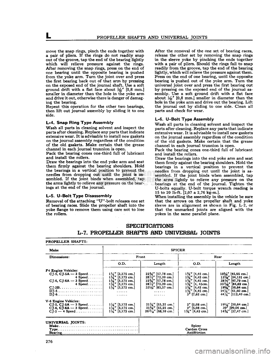
SPECIFICATIONS
L-7.
PROPELLER
SHAFTS
AND
UNIVERSAL JOINTS
PROPELLER
SHAFTS:
Make
SPICER
Dimensions:
F4
Engine Vehicles:
CJ-5,
CJ-5
A
— 3 Speed.
......
4 Speed
CJ-6,
CJ-6A
— 3 Speed 4 Speed
CJ-3B
DJ-5
DJ-6.
V-6
Engine Vehicles:
CJ-5,
CJ-5A
— 3 Speed.
CJ-6,
CJ-6A
— 3 Speed.
CJ-5
— 4 Speed
Front
Rear
Dimensions:
F4
Engine Vehicles:
CJ-5,
CJ-5
A
— 3 Speed.
......
4 Speed
CJ-6,
CJ-6A
— 3 Speed 4 Speed
CJ-3B
DJ-5
DJ-6.
V-6
Engine Vehicles:
CJ-5,
CJ-5A
— 3 Speed.
CJ-6,
CJ-6A
— 3 Speed.
CJ-5
— 4 Speed
O.D.
Length
O.D.
Length
Dimensions:
F4
Engine Vehicles:
CJ-5,
CJ-5
A
— 3 Speed.
......
4 Speed
CJ-6,
CJ-6A
— 3 Speed 4 Speed
CJ-3B
DJ-5
DJ-6.
V-6
Engine Vehicles:
CJ-5,
CJ-5A
— 3 Speed.
CJ-6,
CJ-6A
— 3 Speed.
CJ-5
— 4 Speed
1M"
[3,175 cm.]
1M*
[3,175 cm.]
\W
[3,175 cm.]
1M*
[3,175 cm.] [3,175 cm.]
\W
[3,175 cm.]
\W
[3,175 cm.] [3,175 cm.] 22^" [57,78 cm.]
28H"
[72,39 cm.]
22M*
[57,78 cm.]
mW
[72,39 cm.]
33He"
[85,57 cm.]
21W
[55,25 cm.]
21%"
[55,25 cm.]
2&*
cm.]
IK"
[4,45 cm.]
1M#
[4,45 cm.]
\%"
[4,45 cm.]
\%"
[4, 45cm.]
IW
[4,45 cm.]
1M*
[4,45 cm.]
3*
[7,62 cm.]
2" [5,08 cm.]
2" [5,08 cm.]
l%" [4,45 cm.]
182£"
[45,95 cm.]
WW
[34,131
cm.]
3SJ4*
[97,79 cm.]
33%"
[84,69 cm.] 19546*
[50,64
cm.]
24^"
[61,60
cm.]
44M*
[112,40
cm.]
19%?
[50,64
cm.] 39* [99,06 cm.]
U%"
[37,47 cm.l
UNIVERSAL
JOINTS:
Make
Spicer
Cardan
Cross
Antifriction
Type
Spicer
Cardan
Cross
Antifriction
Bearing
Spicer
Cardan
Cross
Antifriction
276
Page 278 of 376
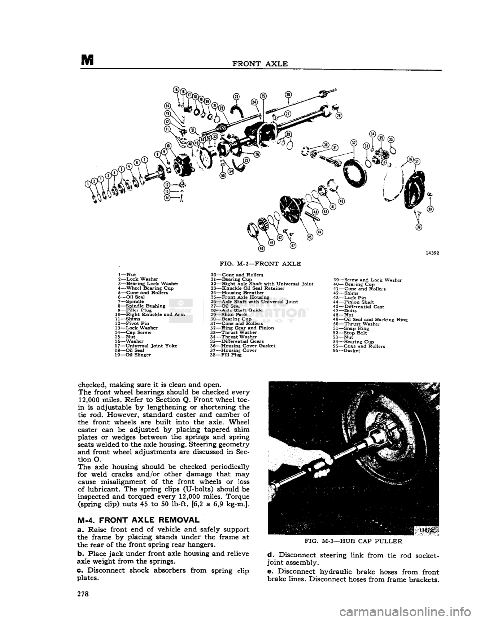
M
FRONT
AXLE
1— Nut
2—
Lock
Washer
3—
Bearing
Lock
Washer
4—
Wheel
Bearing Cup 5—
Cone
and Rollers
6—
Oil
Seal 7— Spindle
8— Spindle Bushing
9—
Filler
Plug
10—
Right
Knuckle and Arm
11— Shims
12— Pivot Pin
13—
Lock
Washer
14—
Cap
Screw
15— Nut
16—
Washer
17—
Universal
Joint Yoke
18—
Oil
Seal
19—
Oil
Slinger
FIG.
M-2—FRONT
AXLE
20—
Cone
and Rollers
21—
Bearing
Cup
22—
Right
Axle Shaft with Universal Joint
23—
Knuckle
Oil Seal Retainer
24— Housing Breather 25—
Front
Axle Housing
26—
Axle
Shaft with Universal Joint
27—
Oil
Seal
28—
Axle
Shaft Guide
29—
Shim
Pack
30—
Bearing
Cup
31—
Cone
and Rollers
32—
Ring
Gear
and Pinion
33—
Thrust
Washer
34—
Thrust
Washer
35—
Differential
Gears
36— Housing Cover Gasket
37— Housing Cover
38—
Fill
Plug 39—
Screw
and
Lock
Washer
40—
Bearing
Cup
41—
Cone
and Rollers
42— Shims
43—
Lock
Pin
44—
Pinion
Shaft
45—
Differential
Case
47— Bolts
48— Nut
49—
Oil
Seal and Backing Ring
50—
Thrust
Washer
51— Snap Ring
52— Stop Bolt
53— Nut 54—
Bearing
Cup
55—
Cone
and Rollers
56—
Gasket
checked, making sure it is clean and open.
The
front wheel bearings should be checked every
12,000
miles. Refer to Section Q. Front wheel toe-
in
is adjustable by lengthening or shortening the
tie rod. However, standard caster and camber of
the front
wheels
are built
into
the axle. Wheel
caster can be adjusted by placing tapered shim
plates or
wedges
between
the springs and spring
seats
welded to the axle housing. Steering
geometry
and
front wheel adjustments are discussed in Sec tion O.
The
axle housing should be checked periodically
for weld cracks and/or other damage that may cause misalignment of the front
wheels
or
loss
of lubricant. The spring clips (U-bolts) should be
inspected and torqued every
12,000
miles. Torque (spring clip) nuts 45 to 50 lb-ft. [6,2 a 6,9 kg-m.].
M-4. FRONT
AXLE
REMOVAL
a.
Raise front end of vehicle
arid
safely support the frame by placing stands under the frame at
the rear of the front spring rear hangers.
b. Place
jack
under front axle housing and relieve
axle
weight
from the springs.
c. Disconnect shock absorbers from spring clip plates.
FIG.
M-3—HUB
CAP
PULLER
d.
Disconnect steering link from tie rod socket-
joint assembly.
e. Disconnect hydraulic brake
hoses
from front
brake
lines. Disconnect
hoses
from frame brackets. 278
Page 282 of 376
FRONT
AXLE
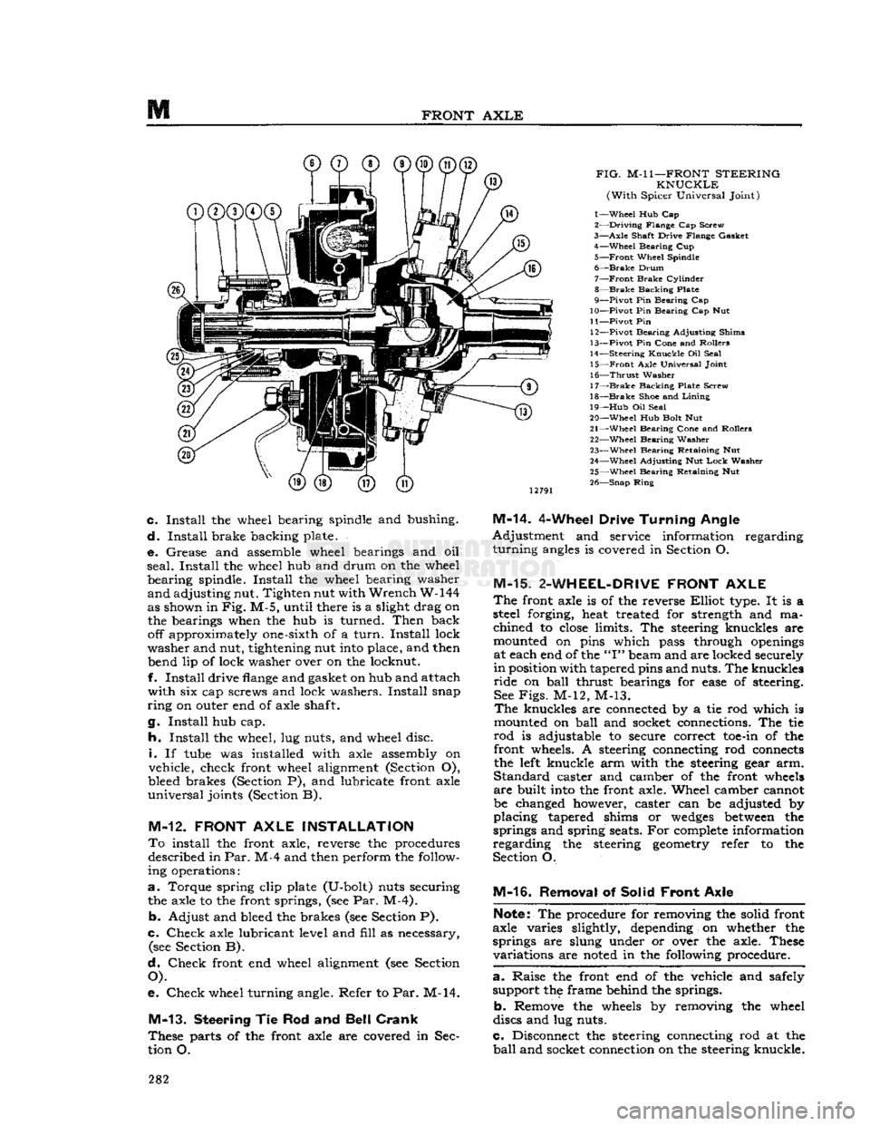
FIG.
M-l
1—FRONT
STEERING
KNUCKLE
(With
Spicer Universal Joint)
1—
Wheel
Hub Cap
2—
Driving
Flange Cap Screw
3—
Axle
Shaft Drive Flange Gasket 4—
Wheel
Bearing Cup
5—
Front
Wheel Spindle
6—
Brake
Drum
7—
Front
Brake
Cylinder
8—
Brake
Backing Plate
9—
Pivot
Pin Bearing Cap
10—
Pivot
Pin Bearing Cap Nut
11—
Pivot
Pin 12—
Pivot
Bearing Adjusting Shims
13—
Pivot
Pin Cone and Rollers
14—
Steering
Knuckle
Oil Seal 15—
Front
Axle Universal Joint
16—
Thrust
Washer
17—
Brake
Backing Plate Screw
18—
Brake
Shoe and
Lining
19—
Hub
Oil Seal
20—
Wheel
Hub Bolt Nut
21—
Wheel
Bearing Cone and Rollers 22—
Wheel
Bearing Washer
23—
Wheel
Bearing Retaining Nut
24—
Wheel
Adjusting Nut
Lock
Washer
25—
Wheel
Bearing Retaining Nut
26—
Snap
Ring
c.
Install
the wheel bearing spindle and bushing.
d.
Install
brake backing plate.
e.
Grease and assemble wheel bearings and oil
seal.
Install
the wheel hub and drum on the wheel
bearing
spindle.
Install
the wheel bearing washer
and
adjusting nut. Tighten nut with
Wrench
W-144
as shown in
Fig.
M-5, until there is a slight drag on the bearings when the hub is turned.
Then
back off approximately one-sixth of a
turn.
Install
lock
washer
and nut, tightening nut
into
place, and then bend lip of lock washer over on the locknut.
f.
Install
drive
flange
and gasket on hub and attach
with
six cap screws and lock washers.
Install
snap
ring
on outer end of axle shaft.
g.
Install
hub cap.
h.
Install
the wheel, lug nuts, and wheel disc.
i.
If
tube
was installed with axle assembly on
vehicle, check front wheel alignment (Section O),
bleed brakes (Section P), and lubricate front axle
universal
joints (Section B).
M-12.
FRONT
AXLE
INSTALLATION
To
install the front axle, reverse the procedures described in
Par.
M-4 and then perform the follow
ing operations:
a.
Torque spring clip plate (U-bolt) nuts securing the axle to the front springs, (see Par. M-4).
b.
Adjust and bleed the brakes (see Section P).
c.
Check
axle lubricant level and
fill
as necessary, (see Section B).
d.
Check
front end wheel alignment (see Section
O).
e.
Check
wheel turning angle. Refer to Par. M-14.
M-13.
Steering
Tie Rod and
Bell Crank
These
parts of the front axle are covered in Sec
tion O.
M-14.
4-Wheel Drive
Turning
Angle
Adjustment
and service information regarding
turning
angles
is covered in Section O.
M-15.
2-WHEEL-DRIVE
FRONT
AXLE
The
front axle is of the reverse
Elliot
type. It is a
steel forging, heat treated for strength and ma
chined
to
close
limits. The steering knuckles are
mounted on pins which pass through
openings
at each end of the
"I"
beam and are locked securely
in
position with tapered pins and nuts. The knuckles
ride
on
ball
thrust bearings for
ease
of steering. See
Figs.
M-12, M-13.
The
knuckles are connected by a tie rod which is
mounted on
ball
and socket connections. The tie
rod
is adjustable to secure correct
toe-in
of the front wheels. A steering connecting rod
connects
the
left
knuckle arm with the steering gear arm.
Standard
caster and camber of the front
wheels
are
built
into
the front axle. Wheel camber cannot
be changed however, caster can be adjusted by
placing
tapered shims or
wedges
between
the
springs and spring seats. For
complete
information
regarding
the steering
geometry
refer to the
Section O.
M-16.
Removal of Solid
Front
Axle
Note:
The procedure for removing the solid front
axle varies slightly, depending on whether the
springs are slung under or over the axle. These
variations
are
noted
in the following procedure.
a. -
Raise the front end of the vehicle and safely support the frame behind the springs.
b.
Remove the
wheels
by removing the wheel
discs and lug nuts.
c.
Disconnect the steering connecting rod at the
ball
and socket connection on the steering knuckle. 282
Page 287 of 376
'Jeep*
UNIVERSAL SERIES SERVICE
MANUAL
N
REAR
AXLE
Contents
PAR. SUBJECT
PAR.
N-l POWR-LOK DIFFERENTIAL
N-20
Chatter
.N-26 Dissasembly and Reassembly. .N-23
Torque Test .N-22
21* Trouble Symptoms N-21
SUBJECT
GENERAL
REAR
AXLE SHAFT
AND
BEARING REMOVAL
Semi-Float-Tapered Axle Shaft
Semi-Float-Flanged Axle Shaft
Semi-Float-Flanged Axle Shaft
Bearing Installation. N-8
UNIT
BEARING ASSEMBLY
N-4 Servicing Unit Bearing. N-5
Lubricating
Unit Bearing............... N-6
Unit
Bearing Removal
.
N-7
REAR
AXLE ASSEMBLY
N-9 Cleaning and Inspection.
..............N-15
Differential Bearing Preload and Ring
Gear
Backlash Adjustment.
..........
.N-l9
Differential Case Disassembly N-l2
Differential Case Reassembly N-l7
Differential Side
Gear
Adjustment. . .... .N-18
Inspection and Servicing N-10 Pinion Bearing Cup Removal .N-l4
Pinion Installation and Adjustments. ... .N-l6 Pinion and Differential Bearing Removal N-13
Rear
Axle Assembly Removal N-ll
N-l. GENERAL
A
semifloating
rear axle assembly is standard on
all
Jeep Universal Series vehicles. Two
models
of
similar
design
rear
axles
are used. See Specifi
cations
Chart,
Par. N-38, for description and ratio.
The
axle
model
number is cast
into
the
housing
as
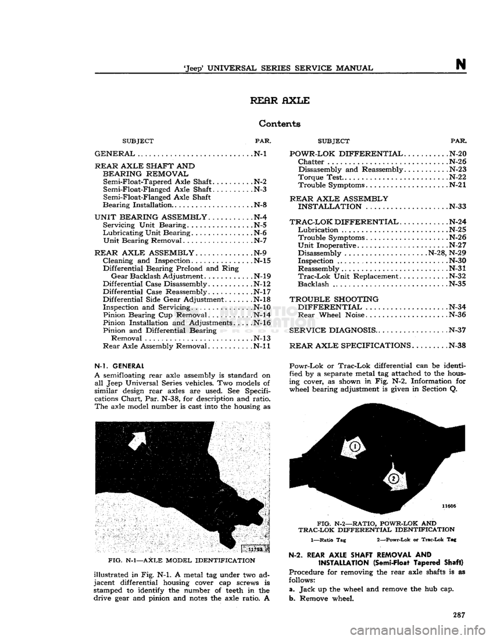
FIG.
N-l—AXLE MODEL IDENTIFICATION
illustrated in Fig. N-l. A metal tag under two ad
jacent differential
housing
cover cap screws is
stamped to
identify
the number of
teeth
in the
drive
gear
and pinion and
notes
the axle ratio. A
REAR
AXLE ASSEMBLY
INSTALLATION
N-33
TRAC-LOK
DIFFERENTIAL.
..........
.N-24
Lubrication
N-25 Trouble Symptoms N-26
Unit
Inoperative N-2 7 Disassembly N-28, N-29 Inspection .N-30
Reassembly .N-31
Trac-Lok
Unit Replacement .N-32
Backlash
N-35
TROUBLE
SHOOTING
DIFFERENTIAL
N-34
Rear
Wheel
Noise
.N-36
SERVICE
DIAGNOSIS
.N-37
REAR
AXLE SPECIFICATIONS.
. N-38
Powr-Lok
or
Trac-Lok
differential can be identi
fied by a separate metal tag attached to the
hous
ing cover, as shown in Fig. N-2. Information for wheel bearing adjustment is
given
in Section Q.
FIG.
N-2—RATIO,
POWR-LOK
AND
TRAC-LOK
DIFFERENTIAL IDENTIFICATION
1—Ratio Tag 2—Powr-Lok or
Trac-Lok
Tag
N-2.
REAR AXLE SHAFT REMOVAL
AND
INSTALLATION
(Semi-Float Tapered Shaft)
Procedure for removing the rear axle
shafts
is as
follows:
a.
Jack
up the wheel and
remove
the hub cap.
b. Remove wheel. 287
Page 288 of 376
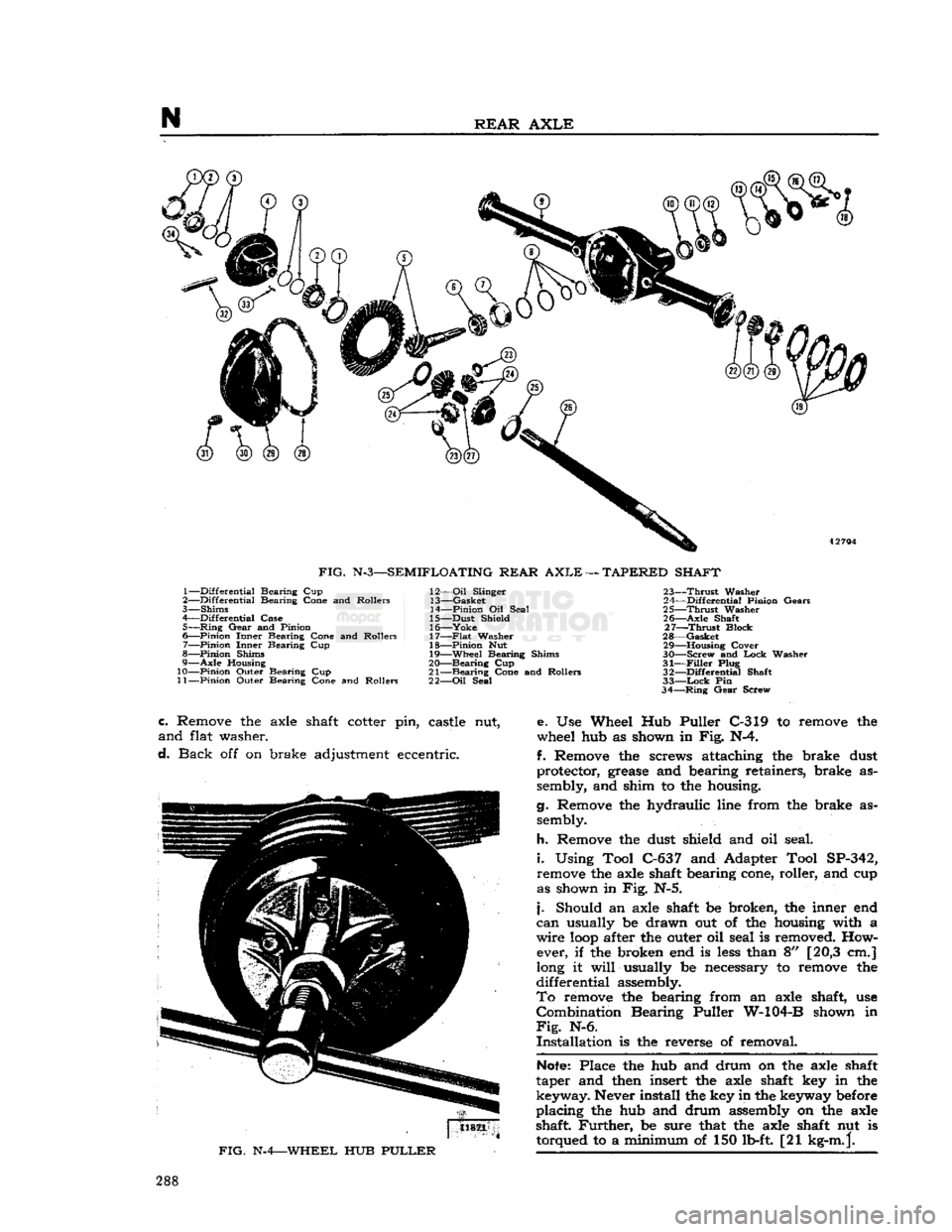
FIG.
N-3—SEMIFLOATING REAR
AXLE
—
TAPERED SHAFT
1— Differential Bearing Cup
2— Differential Bearing Cone and Rollers
3— Shims
4— Differential Case 5—
Ring
Gear and Pinion
6— Pinion Inner Bearing Cone and Rollers
7— Pinion Inner Bearing Cup
8— Pinion Shims
9— Axle
Housing
10— Pinion Outer Bearing Cup
11— Pinion Outer Bearing Cone and Rollers 12—
Oil
Slinger
13— Gasket
14— Pinion Oil Seal
15— Dust Shield
16— Yoke
17—
Flat
Washer
18— Pinion Nut 19— Wheel Bearing Shims
20— Bearing Cup
21— Bearing Cone and Rollers
22—
Oil
Seal 23—
Thrust
Washer
24— Differential Pinion Gears
25—
Thrust
Washer
26— Axle Shaft 27—
Thrust
Block
28— Gasket 29—
—Housing
Cover
30— —Screw and Lock Washer
31—
Filler
Plug 32— Differential Shaft
33—
Lock
Pin
34—
Ring
Gear Screw
c.
Remove the axle shaft cotter pin, castle nut,
and
flat washer.
d.
Back
off on brake adjustment eccentric.
FIG.
N-4—WHEEL
HUB
PULLER
e. Use Wheel Hub Puller C-319 to remove the
wheel hub as shown in Fig. N-4.
f. Remove the screws attaching the brake dust
protector, grease and bearing retainers, brake as
sembly, and shim to the housing.
g. Remove the hydraulic line from the brake as sembly.
h.
Remove the dust shield and oil seal.
i.
Using Tool C-637 and Adapter Tool SP-342,
remove the axle shaft bearing cone, roller, and cup
as shown in Fig. N-5.
j.
Should an axle shaft be broken, the inner end
can
usually be drawn out of the housing with a
wire
loop
after the outer oil seal is removed. How ever, if the broken end is
less
than 8" [20,3 cm.]
long it
will
usually be necessary to remove the
differential
assembly.
To
remove the bearing from an axle shaft, use
Combination
Bearing Puller W-104-B shown in
Fig.
N-6.
Installation
is the reverse of removal.
Note:
Place the hub and drum on the axle shaft
taper and then insert the axle shaft key in the
keyway.
Never install the key in the keyway before
placing
the hub and drum assembly on the axle
shaft
Further,
be sure that the axle shaft nut is torqued to a minimum of 150 lb-ft. [21 kg-m.j. 288
Page 292 of 376
N
REAR
AXLE
FIG.
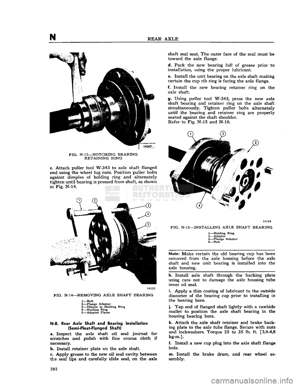
N-l3—NOTCHING
BEARING
RETAINING
RING
c.
Attach puller
tool
W-343 to axle shaft flanged
end using the wheel lug nuts. Position puller
bolts
against dimples of holding ring and alternately tighten until bearing is pressed from shaft, as shown
in
Fig. N-14. 14152
FIG.
N-14—REMOVING
AXLE
SHAFT
BEARING
1—
Bolt
2—
Flange
Adapter
3—
Dimple
in Holding
Ring
4 Holding
Ring
5—
Adapter
Plates N-8.
Rear
Axle
Shaft and Bearing Installation
(Semi-Float-Flanged
Shaft)
a.
Inspect the axle shaft oil seal
journal
for
scratches and polish with fine crocus cloth if
necessary.
b.
Install
retainer plate on the axle shaft
c.
Apply grease to the new oil seal cavity
between
the seal lips and carefully slide seal, on the axle shaft seal seat. The outer face of the seal must be
toward
the axle flange.
d.
Pack
the new bearing
full
of grease
prior
to
installation,
using the proper lubricant.
e.
Install
the unit bearing on the axle shaft making
certain
the cup rib ring is facing the axle flange.
f.
Install
the new bearing retainer ring on the axle shaft.
g. Using puller
tool
W-343, press the new axle shaft bearing and retainer ring on the axle shaft
simultaneously. Tighten puller
bolts
alternately
until
the bearing and retainer ring are properly
seated
against the shaft shoulder.
Refer
to Fig. N-15 and N-16. 14154
FIG.
N-15—INSTALLING
AXLE
SHAFT
BEARING
1—
Holding
Ring
2—
Adapter
3—
Flange
Adapter
4—
Bolt
Note:
Make certain the old bearing cup has
been
removed from the axle housing
before
the axle
shaft and new unit bearing is installed
into
the
axle housing.
h.
Install
axle shaft through the backing plate
using care not to damage the axle housing
tube
inner
oil seal.
i.
Apply a thin coating of lubricant to the
outside
diameter of the bearing cup
prior
to installing in
the bearing bore.
j.
Tap end of flanged shaft lightly with a rawhide
mallet to position the axle shaft bearing in the
housing bearing bore.
k.
Attach the axle shaft retainer and brake back
ing plate to the axle
tube
flange. Secure with nuts
and
lockwashers. Torque 25 to 35 lb. ft
[3,4-4,8
kg-m.].
I.
Install
a new cup plug
into
the axle shaft
flange
hole.
m.
Install
the brake
drum,
and
rear
wheel as
sembly. 292
Page 298 of 376
N
REAR
AXLE
with
a micrometer and add
together
to get total
shim
pack thickness from original buildup.
Note
the (-j-) or (—) etching on both the old pinion and the new one, and adjust the thickness of new shim
pack
to compensate for the difference
between
these
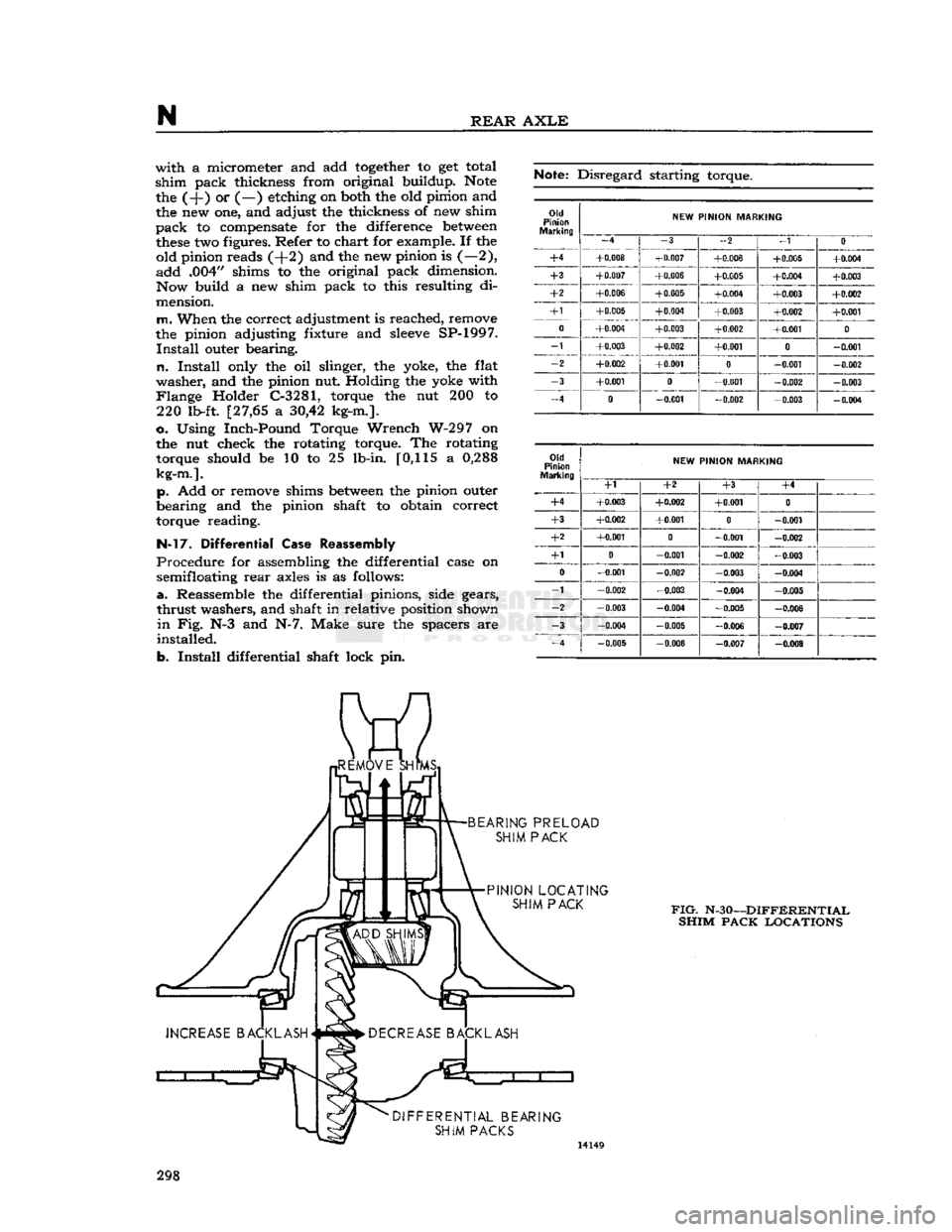
two figures. Refer to chart for example. If the old pinion reads (+2) and the new pinion is (—2),
add
.004" shims to the original pack dimension. Now build a new shim pack to this resulting di
mension.
m.
When the correct adjustment is reached, remove
the pinion adjusting fixture and
sleeve
SP-1997.
Install
outer bearing.
n.
Install
only the oil slinger, the yoke, the flat
washer,
and the pinion nut Holding the yoke with
Flange
Holder C-3281, torque the nut 200 to 220 lb-ft. [27,65 a
30,42
kg-m.].
o. Using Inch-Pound Torque Wrench W-297 on
the nut check the rotating torque. The rotating torque should be 10 to 25 lb-in. [0,115 a
0,288
kg-m.].
p. Add or remove shims
between
the pinion outer
bearing and the pinion shaft to obtain correct
torque reading.
N-l7.
Differential Case Reassembly
Procedure
for assembling the differential case on semifloating
rear
axles is as follows:
a.
Reassemble the differential pinions, side gears,
thrust
washers, and shaft in relative position shown
in
Fig. N-3 and N-7. Make sure the spacers are
installed.
b.
Install
differential shaft lock pin.
Note:
Disregard starting torque.
Old
Pinion
NEW
PINION MARKING
-4 -3
-2 _1
0
+4
+0.008
+0.007
+0.006 +0.005 +0.004
+3
+0.007 +0.006
+0.005 +0.004
+0.003
+2
+0.006
+0.005
+0.004 +0.003 +0.002
+1
+0.005 +0.004
+0.003 +0.002 +0.001
0
+0.004
+0.003 +0.002
+0.001
0
_1
+0.003 +0.002 +0.001
0
-0.001
-2
+0.002 +0.001
0
-0.001 -0.002
-3
+0.001
0
-0.001 -0.002
-0.003
-4
0
-0.001 -0.002
-0.003 -0.004
Old
Pinion
Marking
NEW
PINION MARKING
Old
Pinion
Marking
+1 +2
+3
+4
+4
+0.003 +0.002 +0.001
0
+3
+0.002
+0.001
0
-0.001
+2
+0.001
0
-0.001 -0.002
+1 0
-0.001
-0.002 -0.003
0
-0.001 -0.002
-0.003 -0.004
-1
-0.002 -0.003
-0.004
-0 005
-2
-0.003 -0.004 -0.005 -0.006
-3
-0.004 -0.005
-0.006 -0.007
_4
-0.005 -0.006
-0.007 -0.008
FIG.
N-30—DIFFERENTIAL
SHIM PACK LOCATIONS
298