ESP JEEP CJ 1953 Service Manual
[x] Cancel search | Manufacturer: JEEP, Model Year: 1953, Model line: CJ, Model: JEEP CJ 1953Pages: 376, PDF Size: 19.96 MB
Page 21 of 376
'Jeep'
UNIVERSAL SERIES SERVICE
MANUAL
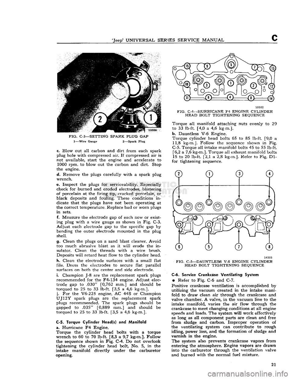
FIG.
C-3—SETTING SPARK PLUG
GAP
1—Wire
Gauge 2—Spark Plug
c.
Blow out all carbon and
dirt
from each
spark
plug hole with compressed air. If compressed air is
not available, start the engine and accelerate to 1000 rpm. to blow out the carbon and
dirt.
Stop
the engine.
d.
Remove the plugs carefully with a
spark
plug
wrench.
e. Inspect the plugs for serviceability. Especially
check
for burned and eroded electrodes, blistering
of porcelain at the firing tip, cracked porcelain, or
black
deposits and fouling. These conditions in
dicate that the plugs have not been operating at
the correct temperature. Replace bad or worn plugs
in
sets.
f. Measure the electrode gap of each new or exist
ing plug with a wire
gauge
as shown in Fig. C-3.
Adjust
each electrode gap to the specific gap by
bending the outer electrode mounted in the plug
shell.
g.
Clean
the plugs on a sand blast cleaner. Avoid
too much abrasive blast as it
will
erode the in
sulator.
Clean
the threads with a wire
brush.
Deposits
will
retard
heat flow to the cylinder head.
h.
Clean
the electrode surfaces with a small flat
file. Dress the electrodes to secure flat parallel surfaces on both the center and side electrode.
i.
Champion J-8 are the replacement
spark
plugs
recommended for the F4-134 engine. Adjust elec
trode gap to .030" [0,762 mm.] and should be
torqued to 25 to 33 lb-ft. [3,5 a 4,6 kg-m.].
j.
For the V6-225 engine, AC 44S or Champion
UJ12Y
spark
plugs are the replacement
spark
plugs recommended. The
spark
plugs should be gapped to .035" [0,889 mm.] and should be
torqued to 25 to 33 lb-ft. [3,5 a 4,6 kg-m.].
C-5. Torque Cylinder
Head(s)
and
Manifold
a.
Hurricane
F4 Engine.
Torque
the cylinder head bolts with a torque
wrench
to 60 to 70 lb-ft [8,3 a 9,7 kg-m.]. Follow
the sequence shown in Fig. C-4. Do not overlook
tightening the cylinder head bolt, No. 5, in the
intake
manifold directly under the carburetor
opening. 10102
FIG.
C-4—HURRICANE
F4
ENGINE CYLINDER HEAD BOLT TIGHTENING SEQUENCE
Torque
all manifold attaching nuts evenly to 29
to 33 lb-ft. [4,0 a 4,6 kg-m.].
b.
Dauntless V-6 Engine.
Torque
cylinder head bolts 65 to 85 lb-ft. [9,0 a 11,8 kg-m.]. Follow the sequence shown in Fig.
C-5.
Torque all intake manifold bolts 45 to 55 lb-ft. [6,2 a 7,6 kg-m.]. Torque all exhaust manifold bolts
15 to 20 lb-ft. [2,1 a 2,8 kg-m.]. Refer to Fig. Dl-
for tightening sequence. 14203
FIG.
C-5—DAUNTLESS
V-6
ENGINE CYLINDER HEAD BOLT TIGHTENING SEQUENCE C-6.
Service
Crankcase
Ventilating System
•
Refer to Fig. C-6 and C-7.
Positive crankcase ventilation is accomplished by
utilizing
the vacuum created in the intake mani
fold to draw clean air through the crankcase and
valve chamber. A valve, in the vacuum line to the
intake
manifold, varies the air flow through the
crankcase
to
meet
changing conditions at all engine
speeds
and loads. The system
will
work effectively as long as all component parts are clean and free
from
sludge and carbon. Improper operation of the ventilating system can contribute to rough
idling,
power loss, and the formation of sludge and
varnish
in the engine.
The
system also prevents crankcase vapors from
entering the atmosphere. Engine vapors are drawn
into the carburetor through the ventilation valve
and
burned with the normal fuel mixture. 21
Page 24 of 376
c
TUNE-UP
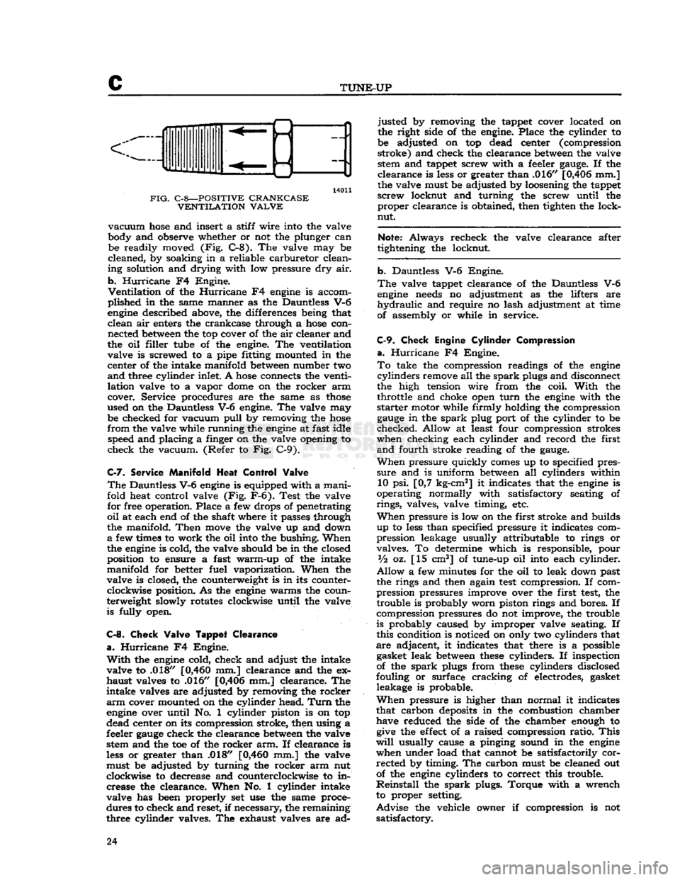
14011
FIG.
C-8—POSITIVE CRANKCASE VENTILATION VALVE
vacuum
hose
and insert a stiff wire into the valve
body and observe whether or not the plunger can be readily moved (Fig. C-8). The valve may be
cleaned, by soaking in a reliable carburetor clean
ing solution and drying with low pressure dry air.
b.
Hurricane
F4 Engine.
Ventilation
of the
Hurricane
F4
engine
is accom
plished in the same manner as the Dauntless V-6
engine
described above, the differences being that clean air enters the crankcase through a
hose
con nected
between
the top cover of the air cleaner and
the oil filler tube of the engine. The ventilation valve is screwed to a pipe fitting mounted in the
center of the intake manifold
between
number two
and
three cylinder inlet. A
hose
connects the venti
lation valve to a vapor
dome
on the rocker arm
cover. Service procedures are the same as
those
used on the Dauntless V-6 engine. The valve may be checked for vacuum
pull
by removing the
hose
from
the valve while running the
engine
at fast idle speed and placing a finger on the valve opening to
check the vacuum. (Refer to Fig. C-9).
C-7.
Service
Manifold
Heat
Control
Valve
The
Dauntless V-6
engine
is equipped with a manifold heat control valve (Fig. F-6). Test the valve
for free operation. Place a few drops of penetrating
oil
at each end of the shaft where it passes through
the manifold.
Then
move
the valve up and down
a
few times to work the oil into the bushing. When
the
engine
is cold, the valve should be in the closed
position to ensure a fast warm-up of the intake
manifold for better fuel vaporization. When the
valve is closed, the counterweight is in its counter clockwise position. As the
engine
warms the coun
terweight slowly rotates clockwise until the valve is fully open.
C-8.
Check
Valve
Tappet
Clearance
a.
Hurricane
F4 Engine.
With
the
engine
cold, check and adjust the intake
valve to .018"
[0,460
mm.] clearance and the ex
haust valves to .016" [0,406 mm.] clearance. The
intake valves are adjusted by removing the rocker
arm
cover mounted on the cylinder head.
Turn
the
engine
over until No. 1 cylinder piston is on top
dead center on its compression stroke, then using a
feeler
gauge
check the clearance
between
the valve stem and the toe of the rocker arm. If clearance is
less
or greater than .018"
[0,460
mm.] the valve
must be adjusted by turning the rocker arm nut
clockwise to decrease and counterclockwise to in crease the clearance. When No. 1 cylinder intake
valve has been properly set use the same proce
dures to check and reset, if necessary, the remaining
three cylinder valves. The exhaust valves are ad justed by removing the tappet cover located on
the right side of the engine. Place the cylinder to
be adjusted on top dead center (compression stroke) and check the clearance
between
the valve stem and tappet screw with a feeler
gauge.
If the
clearance is
less
or greater than .016" [0,406 mm.]
the valve must be adjusted by loosening the tappet
screw locknut and turning the screw until the proper clearance is obtained, then tighten the lock-
nut.
Note:
Always recheck the valve clearance after
tightening the locknut.
b. Dauntless V-6 Engine.
The
valve tappet clearance of the Dauntless V-6
engine
needs
no adjustment as the lifters are
hydraulic
and require no lash adjustment at time
of assembly or while in service.
C-9.
Check
Engine
Cylinder
Compression
a.
Hurricane
F4 Engine.
To
take the compression readings of the
engine
cylinders
remove all the
spark
plugs and disconnect
the high tension wire from the coil.
With
the throttle and choke open
turn
the
engine
with the
starter
motor while firmly holding the compression
gauge
in the
spark
plug port of the cylinder to be
checked. Allow at least four compression strokes
when checking each cylinder and record the first
and
fourth stroke reading of the
gauge.
When
pressure quickly
comes
up to specified pres
sure
and is uniform
between
all cylinders within 10 psi. [0,7 kg-cm2] it indicates that the
engine
is
operating normally with satisfactory seating of
rings,
valves, valve timing, etc.
When
pressure is low on the first stroke and builds
up to
less
than specified pressure it indicates com
pression leakage usually attributable to rings or
valves. To determine which is responsible, pour
Vz
oz. [15 cm3] of tune-up oil into each cylinder.
Allow
a few minutes for the oil to leak down past
the rings and then again
test
compression. If com
pression pressures improve over the first
test,
the trouble is probably worn piston rings and bores. If
compression pressures do not improve, the trouble
is probably caused by improper valve seating. If
this condition is noticed on only two cylinders that
are adjacent, it indicates that there is a possible gasket leak
between
these
cylinders. If inspection
of the
spark
plugs from
these
cylinders disclosed
fouling or surface cracking of electrodes, gasket leakage is probable.
When
pressure is higher than normal it indicates
that carbon
deposits
in the combustion chamber have reduced the side of the chamber enough to
give
the
effect
of a raised compression ratio.
This
will
usually cause a pinging sound in the
engine
when under load that cannot be satisfactorily corrected by timing. The carbon must be cleaned out
of the
engine
cylinders to correct this trouble.
Reinstall
the
spark
plugs. Torque with a wrench
to proper setting.
Advise
the vehicle owner if compression is not satisfactory. 24
Page 25 of 376
'Jeep*
UNIVERSAL SERIES SERVICE
MANUAL
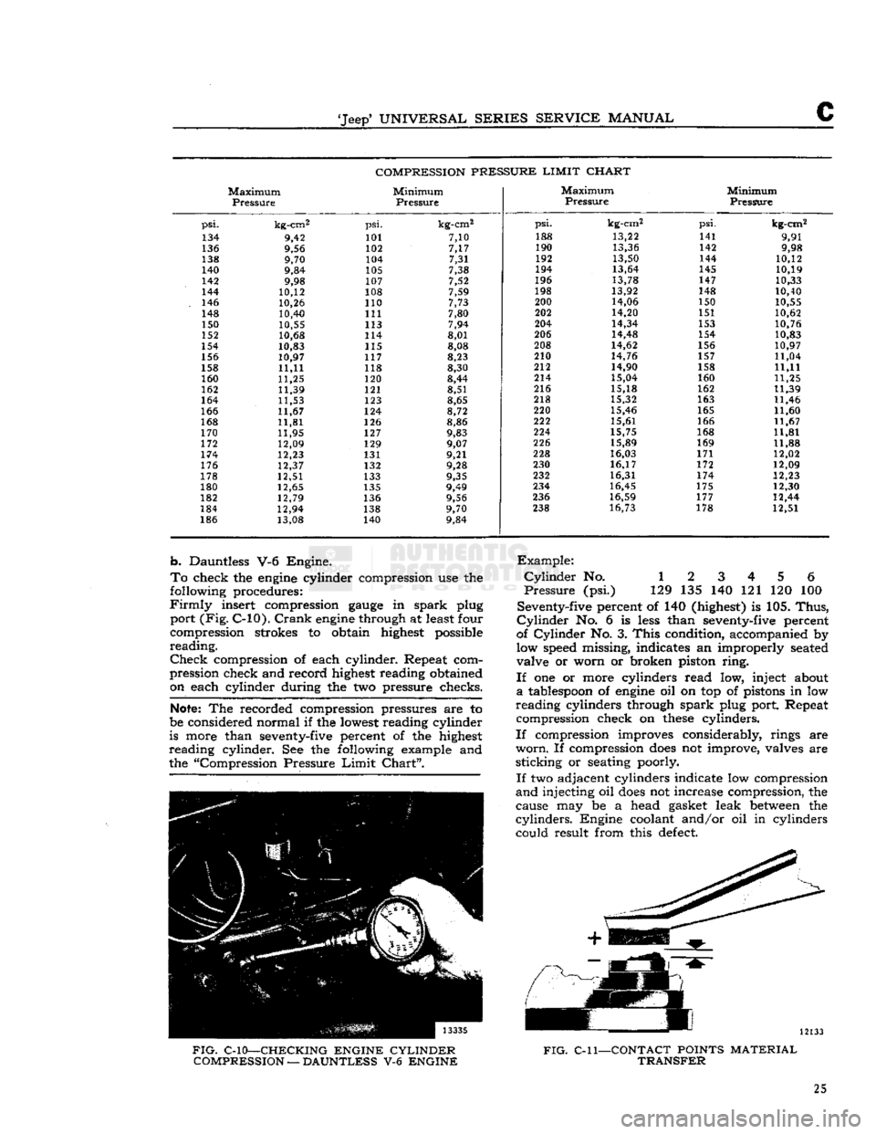
COMPRESSION PRESSURE LIMIT CHART
Maximum
Pressure
Minimum
Pressure
Maximum
Pressure
Minimum
Pressure
psi.
kg-cm2
psi.
kg-cm2
psi.
kg-cm2
psi.
kg-cm2
134 9,42 101 7,10
188
13,22 141
9,91
136 9,56 102 7,17 190
13,36 142
9,98
138 9,70 104 7,31 192
13,50 144 10,12
140 9,84 105 7,38 194
13,64 145
10,19
142 9,98 107 7,52 196
13,78 147 10,33
144 10,12 108 7,59 198
13,92
148 10,40
146 10,26 110 7,73 200
14,06 150 10,55
148 10,40 111 7,80
202
14,20 151
10,62
150 10,55 113 7,94 204
14,34 153
10,76
152 10,68 114 8,01 206
14,48 154 10,83
154 10,83
115 8,08 208
14,62 156
10,97
156 10,97 117 8,23
210
14,76 157 11,04
158 11,11 118 8,30 212
14,90
158 11,11
160 11,25 120
8,44 214
15,04 160
11,25
162 11,39 121 8,51 216
15,18 162 11,39
164 11,53
123 8,65 218
15,32 163
11,46
166 11,67 124 8,72 220
15,46 165 11,60
168 11,81 126 8,86 222
15,61 166
11,67
170 11,95 127 9,83 224
15,75 168 11,81
172 12,09 129 9,07 226
15,89 169
11,88
174 12,23 131 9,21 228
16,03 171 12,02
176 12,37 132 9,28 230
16,17 172
12,09
178 12,51 133 9,35 232
16,31
174 12,23
180 12,65 135 9,49
234
16,45 175 12,30
182 12,79 136 9,56 236
16,59 177 12,44
184 12,94 138 9,70
238
16,73 178 12,51
186 13,08 140 9,84
b.
Dauntless V-6 Engine.
To
check the
engine
cylinder compression use the
following procedures:
Firmly
insert compression
gauge
in
spark
plug
port
(Fig.
C-10).
Crank
engine
through at least four
compression strokes to obtain highest possible
reading.
Check
compression of each cylinder. Repeat com
pression check and record highest reading obtained on each cylinder during the two pressure checks.
Note:
The recorded compression pressures are to
be considered normal if the lowest reading cylinder
is more than seventy-five percent of the highest
reading
cylinder. See the following example and
the "Compression Pressure
Limit
Chart".
Example:
Cylinder
No. 1 2 3 4 5 6
Pressure
(psi.) 129 135 140 121 120 100
Seventy-five percent of 140 (highest) is 105.
Thus,
Cylinder
No. 6 is
less
than seventy-five percent
of
Cylinder
No. 3.
This
condition, accompanied by low speed missing, indicates an improperly seated
valve or worn or broken piston
ring.
If
one or more cylinders read low, inject about
a
tablespoon of
engine
oil on top of pistons in low
reading
cylinders through
spark
plug port. Repeat compression check on
these
cylinders.
If
compression improves considerably, rings are
worn.
If compression
does
not improve, valves are
sticking
or seating poorly.
If
two adjacent cylinders indicate low compression
and
injecting oil
does
not increase compression, the
cause may be a head gasket leak
between
the
cylinders.
Engine coolant and/or oil in cylinders could result from this
defect.
FIG.
C-10—CHECKING ENGINE CYLINDER
COMPRESSION
—
DAUNTLESS
V-6
ENGINE
FIG.
C-l
1—CONTACT
POINTS
MATERIAL
TRANSFER
25
Page 53 of 376
'Jeep'
UNIVERSAL
SERIES
SERVICE
MANUAL
D
satisfactory bearing replacement cannot be made
and
it
will
be necessary to regrind the crankshaft.
Install
the bearing lower
half
and the connecting
rod
cap and draw the cap bolt nuts down equally
and
only slightly tight. Move the connecting rod
endwise, one way or the other, on the crankshaft to be sure the bearing is not tight.
Pull
the nuts tighter, first one then the other, a little at a time,
and
keep trying the fit of the rod on the crankshaft by hand until the recommended torque of 35 to 45 lb-ft. [4,8 a 6,2 kg-m.] is reached. If the
bearings are of the correct size, and have been
properly
lubricated with light
engine
oil before in
stallation,
the connecting rod should be easy to
slide back and forth parallel to the
crankpin.
If
the connecting rod is tight on the crankshaft, a
larger
bearing is required. If there is no binding
or
tightness, it is
still
necessary to check clearance
to guard against too
loose
a fit. The use of "Plasti
gage"
or shim stock of the proper size to measure .001" [0,025 mm.] clearance is recommended for
checking
connecting rod bearing clearances.
This
is the same material recommended for checking
crankshaft
main bearings and the method of check
ing is
similar.
Refer to
Par.
D-45 or D-46. Connect
ing rod bearings are fitted to the same clearance as the main bearings but the torque specified for con
necting rod cap
bolts
is different.
D-50.
Connecting
Rod
Side Play
Check
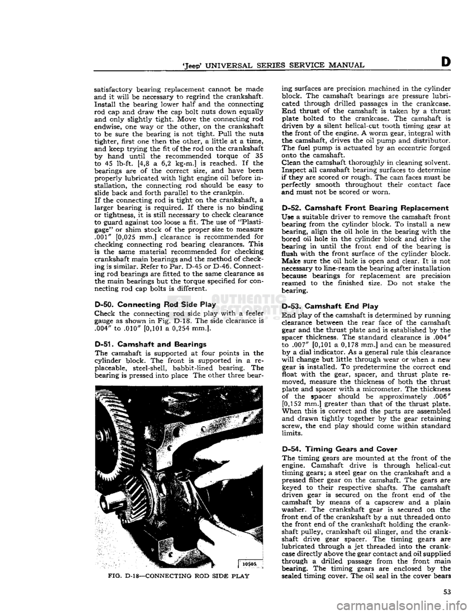
the connecting rod side play with a feeler
gauge
as shown in Fig. D-l8. The side clearance is .004" to .010"
[0,101
a
0,254
mm.].
D-51.
Camshaft and Bearings
The
camshaft is supported at four points in the
cylinder
block. The front is supported in a re placeable, steel-shell, babbit-lined bearing. The
bearing
is pressed into place The other three bear-
FIG.
D-18—CONNECTING
ROD
SIDE
PLAY
ing surfaces are precision machined in the cylinder
block. The camshaft bearings are pressure
lubri
cated through drilled passages in the crankcase.
End
thrust of the camshaft is taken by a thrust plate bolted to the crankcase. The camshaft is
driven
by a silent helical-cut
tooth
timing gear at
the front of the engine. A worm gear, integral with
the camshaft, drives the oil pump and distributor.
The
fuel pump is actuated by an eccentric forged
onto
the camshaft.
Clean
the camshaft thoroughly in cleaning solvent.
Inspect
all camshaft bearing surfaces to determine
if
they are scored or rough. The cam faces must be
perfectly smooth throughout their contact face
and
must not be scored or worn.
D-52.
Camshaft
Front Bearing Replacement
Use
a suitable driver to remove the camshaft front
bearing
from the cylinder block. To install a new
bearing,
align the oil
hole
in the bearing with the
bored oil
hole
in the cylinder block and drive the
bearing
in until the front end of the bearing is
flush
with the front surface of the cylinder block.
Make
sure the oil
hole
is open and clear. It is not
necessary to line-ream the bearing after installation because bearings for replacement are precision
reamed
to the finished size. Do not stake the
bearing.
D-53-
Camshaft End Play
End
play of the camshaft is determined by running
clearance
between
the
rear
face of the camshaft gear and the thrust plate and is established by the
spacer
thickness. The standard clearance is .004"
to .007"
[0,101
a 0,178 mm.] and can be measured by a
dial
indicator. As a general rule this clearance
will
change but little through wear or when a new gear is installed. To predetermine the correct end
float with the gear, spacer, and thrust plate re
moved, measure the thickness of both the thrust
plate and spacer with a micrometer. The thickness
of the spacer should be approximately .006" [0,152 mm.] greater than that of the thrust plate.
When
this is correct and the parts are assembled
and
drawn tightly
together
by the gear retaining
screw,
the end play should
come
within standard
limits.
D-54.
Timing Gears
and
Cover
The
timing gears are mounted at the front of the
engine. Camshaft drive is through helical-cut
timing gears; a steel gear on the crankshaft and a
pressed fiber gear on the camshaft. The gears are keyed to their respective shafts. The camshaft
driven
gear is secured on the front end of the
camshaft by means of a capscrew and a plain
washer.
The crankshaft gear is secured on the
front end of the crankshaft by a nut threaded
onto
the front end of the crankshaft holding the
crank
shaft pulley, crankshaft oil slinger, and the
crank
shaft drive gear spacer. The timing gears are
lubricated
through a jet threaded into the
crank
case directly above the gear contact and oil supplied
through a drilled passage from the front main
bearing.
The timing gears are enclosed by the
sealed timing cover. The oil seal in the cover bears 53
Page 55 of 376
'Jeep'
UNIVERSAL
SERIES SERVICE
MANUAL
develop
into surface cracks and cause failure.
Measure
the over all free length of the springs and
replace any that do not measure to standard: 1%" [35,7 mm.] for intake valve springs and 2j^"
[63,5 mm.] for exhaust valve springs. If possible,
check each valve spring in a valve spring testing
fixture C-647 or equivalent as shown in Fig. D-l9.
Test
each spring when compressed to the two
different spring lengths given (representing valve closed and valve open spring length). If any spring
fails to register spring tension equal to or greater
than
the minimum load limit in pounds specified for that spring length, replace the spring.
Length
Minimun
Load
Intake
valve spring. . .
1.660"
[4,216 cm.] 66 lb. [29,9 kg.]
1.400"
[3,556 cm.] 140 lb. [63,5 kg.]
Exhaust
valve spring. 2.109" [5,356 cm.] 47 lb. [21,3 kg.]
1.750"
[4,445 cm.] 110 lb. [49,9 kg.]
Note:
When using a spring checking fixture C-647
or
equivalent as shown in Fig. D-l9, it is necessary
to convert the torque wrench reading which is in pounds-feet to the static pound pressure specified above according to the instructions furnished with
the wrench. For example, should the torque wrench reading be 50 lb-ft. and the wrench is two
feet
long
the static pressure of the spring
will
be 50 x 2 or 100 lbs.
Clean
the valve
guides
with a standard valve guide
cleaner or a wire
brush.
Check
the valve
guides
in the cylinder block. Replace valve
guides
which are
broken
or worn enough to cause excessive valve
stem-to-guide
clearance. See Par. D-61.
Standard
intake valve clearance is .0007" to .0022"
[0,0178
a
0,0559
mm.] and the exhaust valve
clearance is .0025" to .0045" [0,0635 a
0,1143
mm.].
Excessive
clearance
between
the valve
stems
and
guides
will
cause improper seating and burned
valves. When there is a tendency to draw oil vapor
through the guide causing excessive oil consump tion, fouled
spark
plugs, and poor low-speed per
formance. To check the clearance of the valve stem
to the valve guide, take a new valve and place in
each valve guide.
Check
the clearance with a
suitably mounted
dial
indicator or feel the clearance by moving the valve stem back and forth. If this
check shows excessive clearance it
will
be necessary to replace the valve guide.
D-58.
Refacing Valves
Re
face the valves with a valve refacer. The valve
refacer
manufacturer's instructions should be fol
lowed carefully to ensure a valve face concentric
with
the valve stem. Reface both intake and ex
haust valves to an angle of 46°.
Take
off only the
minimum
of metal required to clean up the valve faces.
If
the thickness of the
edge
of the valve head is
reduced to
less
than
J^>"
[0>8 mm.] replace the valve.
Note:
Cocked or deformed valve springs or im
properly
installed or missing locks can be responsible
for valve problems.
D-59.
Valve Seat Inspection
and
Refacing
Inspect the valve
seats
for
cracks,
burns, pitting,
ridges, or improper angle.
During
any general
engine
overhaul it is advisable to reface the valve
seats
in both the cylinder block and head regardless
of their condition. If the valve
guides
are to be re placed, this must be
done
before refacing the valve
seats.
Note
that later
engines
have hardened
exhaust valve seat inserts.
Valve
seat inserts must be concentric with finish
ream
of valve stem
guides
(exhaust) within .002"
[0,051
mm.] total indicator reading.
When
necessary to reface the valve seats, use a
valve seat grinder in accordance with the grinder
manufacturer's
instructions. Any grinding of valve
seats
should be preceded by touching up the
grinding
stone
so that their angles are accurate and
the
stone
is not
clogged.
Grind
each valve seat to
a
true 45° angle. Never grind any more than is necessary to clean up pits, grooves, or to correct
the valve seat runout.
Check
the valve
seats
with
10465
FIG.
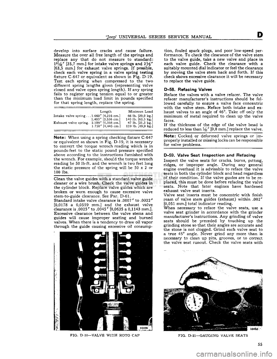
D-20—VALVE
WITH
ROTO
CAP
FIG.
D-21—GAUGING
VALVE
SEATS
55
Page 63 of 376
![JEEP CJ 1953 Service Manual
Jeep
UNIVERSAL SERIES SERVICE
MANUAL
D
is .004" to .007"
[0,102
a 0,178 mm.] as measured
by a dial indicator. Should a check
show
too little
end play, place a shim of suitable thickness
JEEP CJ 1953 Service Manual
Jeep
UNIVERSAL SERIES SERVICE
MANUAL
D
is .004" to .007"
[0,102
a 0,178 mm.] as measured
by a dial indicator. Should a check
show
too little
end play, place a shim of suitable thickness](/img/16/57040/w960_57040-62.png)
'Jeep'
UNIVERSAL SERIES SERVICE
MANUAL
D
is .004" to .007"
[0,102
a 0,178 mm.] as measured
by a dial indicator. Should a check
show
too little
end play, place a shim of suitable thickness
between
the camshaft shoulder and the spacer. Too much
end play may be corrected by removing shims or
dressing off the spacer a slight amount. See Fig. D-33.
D-82. Install Crankshaft and Bearings
Fit
the three upper main bearings
into
their
respective
locations
in the cylinder block. Fit the
three lower main bearings
into
their respective
bearing caps.
NOTE:
It is
possible
to incorrectly install the front main bearing. The bearing is properly installed in
the cap with the narrower of the two radial oil
grooves
toward the front
edge
of the cap. If this
bearing is not properly installed, the oil
grooves
in
the two halves of the bearing will not match at the
parting line and premature failure of the bearing
will
result.
Lubricate
all bearing surfaces
generously
with
clean, light
engine
oil. Place the crankshaft in
position
in the cylinder block and install the main
bearing caps. Torque the
bolts
65 to 75 lb-ft.
[9,0 a 10,4 kg-m.] rotating the crankshaft after
each bearing cap is
tightened
D-83. Check Crankshaft End-Play
End
play of the crankshaft is set by the running
clearance
between
the crankshaft thrust washer
and the front
face
of the front main bearing. The
standard end play is .004" to .006"
[0,102
a 0,152
mm.] which is controlled by .002"
[0,051
mm.]
shims placed
between
the thrust washer and the
shoulder on the crankshaft. Check the end play
with a dial indicator as shown in
Fig.
D-34. If clear ance is incorrect, adjustment is made by adding or
removing shims.
Install
the thrust washer with the
beveled
inner
edge
toward the front bearing.
10668
FIG.
D-33—VALVES, CAMSHAFT,
AND
TIMING GEARS
1— Nut
2—
Left
Rocker Arm
3—
Rocker
Arm Shaft Spring
4—
Rocker
Shaft
Lock
Screw 5—
Rocker
Shaft
6— Nut 7—
Right
Rocker Arm
8—
Rocker
Arm Shaft Bracket
9—
Intake
Valve Tappet Adjusting Screw
10—
Intake
Valve Upper Retainer
Lock
11—
Oil
Seal
12—
Intake
Valve Spring Upper Retainer 13—
Intake
Valve Spring
14—
Intake
Valve Push Rod 15—
Intake
Valve
16—
Intake
Valve Tappet
17—
Camshaft
18—
Camshaft
Front Bearing
19—
Camshaft
Thrust Plate Spacer
20—
Camshaft
Thrust Plate
21— Bolt and Lockwasher
22— Bolt 13—Lockwasher
24—Camshaft
Gear
Washer 25—
Crankshaft
Gear
26—
Camshaft
Gear
27— Woodruff Key No. 9
28—
Exhaust
Valve Tappet
29— Tappet Adjusting Screw
30—
Spring
Retainer
Lock
31— Roto Cap Assembly
32—
Exhaust
Valve Spring
33—
Exhaust
Valve
34—
Rocker
Shaft Support Stud
35—
Washer
36—
Rocker
Arm Cover Stud 63
Page 66 of 376
D
HURRICANE
F4
ENGINE
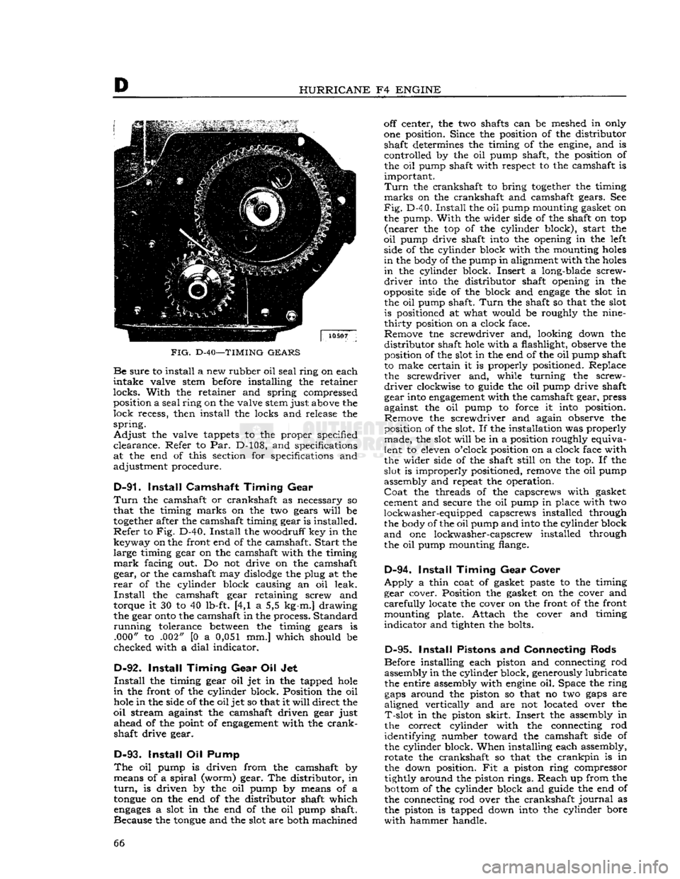
FIG.
D-40—TIMING
GEARS Be
sure
to install a new rubber oil
seal
ring on each
intake
valve stem before installing the retainer
locks.
With
the retainer and spring compressed position a
seal
ring
on the valve stem just above the
lock
recess, then install the locks and release the
spring.
Adjust
the valve tappets to the proper specified
clearance.
Refer to Par. D-108, and specifications
at the end of this section for specifications and
adjustment procedure.
D-91.
Install
Camshaft
Timing
Gear
Turn
the camshaft or crankshaft as necessary so
that the timing marks on the two gears
will
be
together
after the camshaft timing gear is installed.
Refer
to Fig. D-40.
Install
the woodruff key in the key way on the front end of the camshaft.
Start
the large timing gear on the camshaft with the timing
mark
facing out. Do not drive on the camshaft gear, or the camshaft may
dislodge
the plug at the
rear
of the cylinder block causing an oil leak.
Install
the camshaft gear retaining screw and
torque it 30 to 40 lb-ft. [4,1 a 5,5 kg-m.] drawing
the gear
onto
the camshaft in the process. Standard
running
tolerance
between
the timing gears is .000" to .002" [0 a 0,051 mm.] which should be
checked with a
dial
indicator.
D-92.
Install
Timing
Gear
Oil Jet
Install
the timing gear oil jet in the tapped
hole
in
the front of the cylinder block. Position the oil
hole
in the side of the oil jet so that it
will
direct the
oil
stream against the camshaft driven gear just
ahead
of the point of
engagement
with the
crank
shaft drive gear.
D-93.
Install
Oil Pump
The
oil pump is driven from the camshaft by means of a
spiral
(worm) gear. The distributor, in
turn,
is driven by the oil pump by means of a
tongue
on the end of the distributor shaft which
engages
a slot in the end of the oil pump shaft.
Because the
tongue
and the slot are both machined off center, the two shafts can be meshed in only
one position. Since the position of the distributor shaft determines the timing of the engine, and is
controlled by the oil pump shaft, the position of the oil pump shaft with respect to the camshaft is
important.
Turn
the crankshaft to bring
together
the timing
marks
on the crankshaft and camshaft gears. See
Fig.
D-4 0.
Install
the oil pump mounting gasket on
the pump.
With
the wider side of the shaft on top
(nearer
the top of the cylinder block), start the
oil
pump drive shaft into the opening in the left side of the cylinder block with the mounting
holes
in
the body of the pump in alignment with the
holes
in
the cylinder block. Insert a long-blade screw
driver
into the distributor shaft opening in the
opposite
side of the block and
engage
the slot in the oil pump shaft.
Turn
the shaft so that the slot is positioned at what would be roughly the nine-
thirty
position on a clock face. Remove tne screwdriver and, looking down the
distributor
shaft
hole
with a flashlight, observe the position of the slot in the end of the oil pump shaft
to make certain it is properly positioned. Replace the screwdriver and, while turning the screw
driver
clockwise to guide the oil pump drive shaft
gear into
engagement
with the camshaft gear, press
against the oil pump to force it into position. Remove the screwdriver and again observe the
position of the slot. If the installation was properly made, the slot
will
be in a position roughly equiva
lent to eleven o'clock position on a clock face with
the wider side of the shaft
still
on the top. If the
slot is improperly positioned, remove the oil pump
assembly and repeat the operation.
Coat
the threads of the capscrews with gasket
cement and secure the oil pump in place with two
lockwasher-equipped capscrews installed through the body of the oil pump and into the cylinder block
and
one lockwasher-capscrew installed through
the oil pump mounting flange.
D-94.
Install
Timing
Gear
Cover
Apply
a thin coat of gasket paste to the timing
gear cover. Position the gasket on the cover and
carefully
locate the cover on the front of the front mounting plate. Attach the cover and timing
indicator
and tighten the bolts.
D-95.
Install
Pistons and Connecting Rods
Before installing each piston and connecting rod assembly in the cylinder block, generously lubricate
the entire assembly with
engine
oil. Space the ring
gaps
around the piston so that no two
gaps
are
aligned vertically and are not located over the
T-slot
in the piston
skirt.
Insert the assembly in
the correct cylinder with the connecting rod
identifying number toward the camshaft side of
the cylinder block. When installing each assembly, rotate the crankshaft so that the
crankpin
is in
the down position. Fit a piston ring compressor
tightly around the piston rings. Reach up from the
bottom
of the cylinder block and guide the end of
the connecting rod over the crankshaft
journal
as
the piston is tapped down into the cylinder bore
with
hammer handle. 66
Page 79 of 376
'Jeep*
UNIVERSAL SERIES SERVICE
MANUAL
Dl
12710
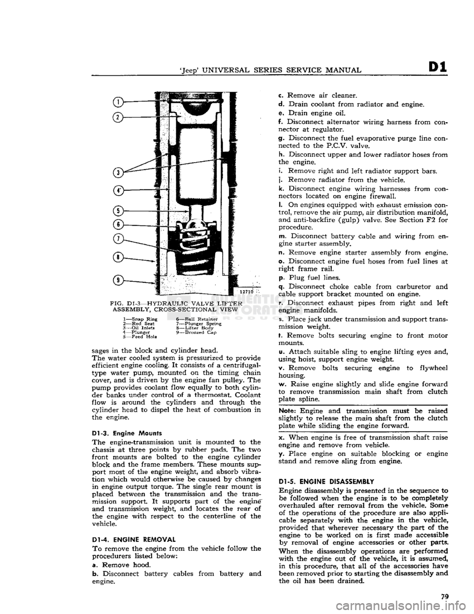
FIG.
D1
-3—HYDRAULIC VALVE
LIFTER
ASSEMBLY, CROSS-SECTIONAL VIEW
1—
Snap
Ring
6—Ball Retainer
2— Rod
Seat
7—Plunger Spring
3—
Oil
Inlets
8—Lifter
Body
4—
Plunger
9—Bronzed
Cap
5— Feed
Hole
sages
in the block and cylinder head.
The
water cooled system is pressurized to provide efficient
engine
cooling. It consists of a centrifugal-
type water pump, mounted on the timing chain cover, and is driven by the
engine
fan pulley. The
pump provides coolant flow equally to both
cylin
der banks under control of a thermostat. Coolant
flow is around the cylinders and through the
cylinder
head to dispel the heat of combustion in
the engine.
Dl-3.
Engine Mounts
The
engine-transmission unit is mounted to the chassis at three points by rubber pads. The two
front mounts are bolted to the
engine
cylinder
block and the frame members. These mounts sup port most of the
engine
weight, and absorb
vibra
tion which would otherwise be caused by changes
in
engine
output torque. The single
rear
mount is
placed
between
the transmission and the trans mission support. It supports part of the engine'
and
transmission weight, and locates the
rear
of
the
engine
with respect to the centerline of the
vehicle.
Dl-4. ENGINE REMOVAL
To
remove the
engine
from the vehicle follow the
procedurers listed below:
a.
Remove hood. b. Disconnect battery cables from battery and
engine. c. Remove air cleaner.
d.
Drain
coolant from radiator and engine.
e.
Drain
engine
oil.
f. Disconnect alternator wiring harness from con nector at regulator.
cj.
Disconnect the fuel evaporative purge line con nected to the
P.C.V.
valve.
h.
Disconnect upper and lower radiator
hoses
from
the engine.
i.
Remove right and left radiator support
bars,
j.
Remove radiator from the vehicle.
k.
Disconnect
engine
wiring harnesses from con
nectors located on
engine
firewall.
I.
On
engines
equipped with exhaust emission con
trol,
remove the air pump, air distribution manifold,
and
anti-backfire (gulp) valve. See Section F2 for
procedure.
m.
Disconnect battery cable and wiring from en
gine
starter assembly.
n.
Remove
engine
starter assembly from engine,
o.
Disconnect
engine
fuel
hoses
from fuel lines at
right
frame
rail,
p. Plug fuel lines.
q.
Disconnect choke cable from carburetor and cable support bracket mounted on engine,
r.
Disconnect exhaust pipes from right and left
engine
manifolds.
s. Place
jack
under transmission and support trans
mission weight.
f. Remove
bolts
securing
engine
to front motor mounts.
u.
Attach suitable sling to
engine
lifting
eyes
and,
using hoist, support
engine
weight.
v. Remove
bolts
securing
engine
to flywheel housing.
w. Raise
engine
slightly and slide
engine
forward
to remove transmission main shaft from clutch plate spline.
Note:
Engine and transmission must be raised
slightly to release the main shaft from the clutch
plate while sliding the
engine
forward.
x. When
engine
is free of transmission shaft raise
engine
and remove from vehicle,
y. Place
engine
on suitable blocking or
engine
stand and remove sling from engine.
Dl-5.
ENGINE DISASSEMBLY
Engine
disassembly is presented in the sequence to be followed when the
engine
is to be completely
overhauled after removal from the vehicle. Some of the operations of the procedure are also applicable separately with the
engine
in the vehicle,
provided that wherever necessary the part of the
engine
to be worked on is first made accessible by removal of
engine
accessories or other parts.
When
the disassembly operations are performed
with
the
engine
out of the vehicle, it is assumed,
in
this procedure, that all of the accessories have
been removed
prior
to starting the disassembly and
the oil has been drained.
Page 86 of 376
Dl
DAUNTLESS
V-6
ENGINE
Dl-38.
Crankshaft
Cleaning
Clean
the crankshaft thoroughly with a suitable
cleaning solvent.
Clean
drilled oil
passages
in its
journals
with a small rifle brush to remove all
sludge
or gum deposits; dry
passages
with com
pressed air.
Dl-39.
Crankshaft
Inspection
and
Repair
If
the crankshaft has not
been
removed from the
cylinder
block for inspection, disconnect two con necting rods at a time from crankshaft. Inspect
the bearings and crankpin journals. While turning
crankshaft,
it is necessary to temporarily reconnect
the rods to crankshaft to avoid possibility of dam aging the journals through contact with uncon
nected rods.
Inspect the crankpins visually for excessive or ir
regular
wear, and for scoring. Use an
outside
micrometer to check crankpins for out-of-round.
Standard
crankpin
diameter is
2.0000"
[5,080
cm.].
If
crankpins are more than .0015"
[0,0381
mm.]
out-of-round, new bearings cannot be
expected
to
have satisfactory life.
If
the crankshaft has
been
removed from the
cyl
inder
block for inspection support it on V-blocks
at its main bearing journals 1 and 4. Inspect the
main
bearing journals visually for excessive or ir
regular
wear, and for scoring. Standard main bear
ing
journal
diameter is 2.4995"
[6,349
cm.].
Total
indicator readings at each
journal
should not ex
ceed .003"
[0,076
mm.].
Check
run out at all four journals and
note
high
spot
(maximum eccentricity) of each
journal.
High
spot
of each
journal
should
come
at the same
angular
location. If high
spots
do not coincide,
crankshaft
is misaligned and unsatisfactory for
service.
If
crankpin or main bearing journals are scored,
ridged, or out-of-round, the crankshaft must be replaced or reground to a standard undersize bear
ing diameter to ensure satisfactory life of bearings. Slight roughness can be removed with a fine grit
polishing cloth thoroughly
wetted
with
engine
oil.
Burrs
can
be
honed with a fine oil
stone,
so long as
bearing clearances
will
remain within specified
limits.
Dl-40.
Crankshaft
Main
Bearings
A
crankshaft bearing consists of two halves which
are
neither alike nor interchangeable. One half is
carried
in the corresponding main bearing cap; the
other half is located
between
the crankshaft and
cylinder
block. The upper (cylinder block) half
of the bearing is grooved to supply oil to the con necting rod bearings, while the lower (bearing cap)
half
of the bearing is not grooved. The two bearing
halves must not be interchanged. All crankshaft
bearings
except
the thrust bearing and the
rear
main
bearing are identical. The thrust bearing (No. 2) is longer and it is flanged to take
crank
shaft end thrust. When the bearing halves are
placed in cylinder block and bearing cap, the
ends
extend slightly beyond the parting surfaces. When
cap
bolts
are tightened, the halves are clamped
tightly in place to ensure positive seating and to
prevent turning. The
ends
of bearing halves must never be filed flush with parting surface of
crank
case or bearing cap.
Crankshaft
bearings are the precision type which
do not require reaming to size or other fitting.
Shims
are not provided for adjustment since worn
bearings are readily replaced with new bearings of proper size. Bearings for service replacement are
furnished
in standard size and undersizes. Under no circumstances should crankshaft bearing caps
be filed to adjust for wear in old bearings.
Dl-41.
Crankshaft
Main
Bearing
Cleaning
and
Inspection
Clean
main bearing surfaces. Inspect the bearings
visually
for excessive or uneven wear, scoring, and
flaking.
Visibly worn or damaged bearings must
be replaced. It is necessary to check
radial
clear ance of each new or used crankshaft main bearing
before installation.
This
can be
done
by either of two methods, which are described in
Pars.
Dl-42
and
Dl-43.
a.
The desired
radial
clearance of a new bearing
is .0005" to .0021"
[0,0127
a
0,0534
mm.].
b. Replacement bearings are furnished in standard
size, and in several undersizes, including undersizes
for reground journals. If a new bearing is to be installed, try a standard size; then try each under
size in turn until one is found that
meets
the
specified clearance limits.
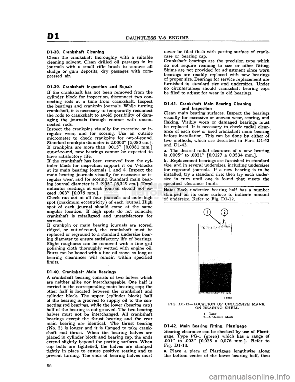
Note:
Each
undersize bearing half has a number
stamped on its outer surface to indicate amount of undersize. Refer to Fig. Dl-12. 14288
FIG.
Dl-12—LOCATION
OF
UNDERSIZE
MARK
ON
BEARING
SHELL
1—
Tang
2—
Undersize
Mark
Dl-42.
Main
Bearing
Fitting,
Plastigage
Bearing
clearance can be checked by use of Plasti
gage,
Type PG-1 (green) which has a range of
.001" to .003" [0,025 a
0,076
mm.]. Refer to
Fig.
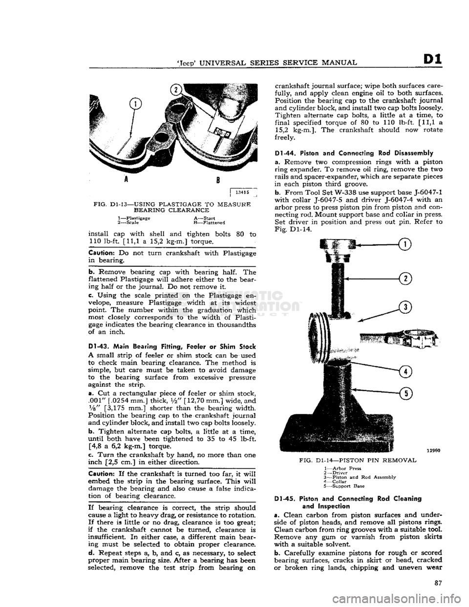
Dl-13.
a.
Place a piece of Plastigage lengthwise along the
bottom
center of the lower bearing half, then 86
Page 87 of 376
'Jeep'
UNIVERSAL
SERIES SERVICE
MANUAL
Dl
A 8
j
13415
FIG.
Dl-13—USING
PLASTIGAGE
TO
MEASURE
BEARING CLEARANCE
1— Plastigage
A—Start
2—
Scale
B—Flattened
install
cap with shell and tighten
bolts
80 to 110 lb-ft. [11,1 a 15,2 kg-m.] torque.
Caution:
Do not turn crankshaft with Plastigage
in
bearing.
b.
Remove bearing cap with bearing half. The
flattened Plastigage
will
adhere either to the bear ing half or the
journal.
Do not remove it.
c. Using the scale printed on the Plastigage en
velope,
measure Plastigage width at its widest
point. The number within the graduation which
most
closely corresponds to the width of Plasti
gage
indicates the bearing clearance in thousandths
of an inch.
DI-43.
Main Bearing
Fitting,
Feeler or
Shim
Stock
A
small strip of feeler or shim stock can be used
to check main bearing clearance. The method is
simple, but care must be taken to avoid damage
to the bearing surface from excessive pressure against the strip.
a.
Cut a rectangular piece of feeler or shim stock, .001"
[.0254
mm.] thick,
i/2"
[12,70
mm.] wide, and
Vs"
[3,175 mm.] shorter than the bearing width.
Position the bearing cap to the crankshaft journal
and
cylinder block, and install two cap
bolts
loosely.
b.
Tighten alternate cap bolts, a little at a time,
until
both have
been
tightened to 35 to 45 lb-ft. [4,8 a 6,2 kg-m.] torque.
c.
Turn
the crankshaft by hand, no more than one
inch
[2,5 cm.] in either direction.
Caution:
If the crankshaft is turned too far, it
will
embed the strip in the bearing surface.
This
will
damage the bearing and also cause a false indication of bearing clearance.
If
bearing clearance is correct, the strip should cause a light to heavy drag, or resistance to rotation.
If
there is little or no drag, clearance is too great;
if
the crankshaft cannot be turned, clearance is
insufficient. In either case, a different main bear ing must be
selected
to obtain proper clearance.
d.
Repeat
steps
a, b, and c, as necessary, to
select
proper main bearing size. After a bearing has
been
selected, remove the
test
strip from bearing on
crankshaft
journal surface; wipe both surfaces care
fully,
and apply clean
engine
oil to both surfaces. Position the bearing cap to the crankshaft journal
and
cylinder block, and install two cap
bolts
loosely.
Tighten
alternate cap bolts, a little at a time, to
final
specified torque of 80 to 110 lb-ft. [11,1 a 15,2 kg-m.]. The crankshaft should now rotate
freely.
Dl-44.
Piston
and
Connecting
Rod
Disassembly
a.
Remove two compression rings with a piston
ring
expander. To remove oil ring, remove the two
rails
and spacer-expander, which are separate
pieces
in
each piston third
groove.
b.
From
Tool Set W-338 use support base J-6047-1
with collar J-6047-5 and driver J-6047-4 with an
arbor
press to press piston pin from piston and con
necting rod. Mount support base and collar in press. Set driver in position and press out pin. Refer to
Fig.
Dl-14.
FIG.
Dl-14—PISTON
PIN
REMOVAL
1—
Arbor
Press
2—
Driver
3—
Piston
and Rod Assembly
4—
Collar
•
5—Support Base Dl-45.
Piston
and
Connecting
Rod
Cleaning
and Inspection
a.
Clean
carbon from piston surfaces and under
side of piston heads, and remove all pistons rings.
Clean
carbon from ring
grooves
with a suitable tool.
Remove any gum or varnish from piston skirts with a suitable solvent.
b.
Carefully examine pistons for rough or scored
bearing surfaces, cracks in
skirt
or head, cracked
or
broken ring lands, chipping and uneven wear 87