Electrical JEEP CJ 1953 Service Manual
[x] Cancel search | Manufacturer: JEEP, Model Year: 1953, Model line: CJ, Model: JEEP CJ 1953Pages: 376, PDF Size: 19.96 MB
Page 1 of 376
1953-71
SERVICE MANUAL
JeeP
UNIVERSAL
4-WHEEL DRIVE
CJ-3B CJ-5A
CJ-5
CJ-6
CJ-6A
2-WHEEL DRIVE DJ-5
DJ-6
Copyright®
1977
FI Jeep Corporation Corporate Publications
Printed
in USA
Reprinted
6-77
SM-1046
SECTION
INDEX
NAME
Section
General
Data
A
Lubrication
B
Tune-Up
C
Hurricane
F4 Engine
D
Dauntless V-6 Engine
Dl
Fuel
System
E
Exhaust
System
F
Exhaust
Emission Control System F4 Engine
Fl
Exhaust
Emission Control System V6-225 Engine
F2
Cooling System
G
Electrical
H
Clutch
I
3-Speed
Transmission
J
4-Speed
Transmission
Jl
Transfer
Case
K
Propeller Shafts
L
Front
Axle
M
Rear
Axle
N
Steering 0
Brakes
P
Wheels 0
Frame
R
Springs
Shock Absorbers
S
Body
T
Miscellaneous
U
Page 2 of 376
IMPORTANT
DEALER
INFORMATION
This
manual, SM-1046, covers current 'Jeep' Universal Series vehicles, and
past models,
except
as
noted
hereinafter:
SM-1037 should be retained in your service
library
for
information related to the
6-volt
electrical system, or the
single brake system.
SM-1002-R5
(no longer available) should be retained
for information related to the
CJ-2A, CJ-3A
or
DJ-3A
models
equipped with the L4-134
engine.
The
above
three manuals provide
full
service coverage since inception of the
'Jeep' Universal and
1
Jeep' Dispatcher model vehicles.
Page 10 of 376
B
LUBRICATION
B-2.
Special Lubricants
Special
lubricants are required for certain
lubri
cation points on the 'Jeep' Universal vehicles. The
special
lubricants are necessary for proper function ing and maintenance of the vehicle. The
Lubrica
tion
Chart
(Fig. B-l and B-2)
designates
the spe
cial
lubricating points and identifies them by type
or
part number.
B-3.
Applying
Fresh
Lubricant
When
servicing or lubricating the vehicle, it is important that all old lubricant and
dirt
be re moved from the fitting and/or plugs before servic
ing and that the recommended type of lubricant be used for the particular item being serviced.
Force
lubricant through the lube fittings until the lubricant being forced out of the joint is fresh
lubricant,
indicating that all old lubricant has
been removed.
B-4.
Engine
Lubrication
System —
Hurricane
F4 Engine
•
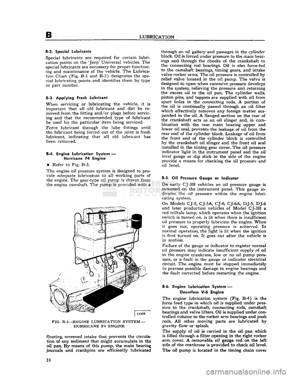
Refer to Fig. B-3.
The
engine
oil pressure system is designed to pro
vide adequate lubrication to all working parts of
the engine. The gear-type oil pump is driven from
the
engine
camshaft. The pump is provided with a
FIG.
B-3—ENGINE
LUBRICATION
SYSTEM
—
HURRICANE
F4
ENGINE
floating, screened intake that prevents the
circula
tion of any sediment that might accumulate in the
oil
pan. By means of this pump, the main bearing
journals
and crankpins are efficiently lubricated through an oil gallery and passages in the cylinder
block.
Oil
is forced under pressure to the main bear
ings and through the cheeks of the crankshaft to
the connecting rod bearings. Oil is also force-fed
to the camshaft bearings, timing gears, and intake valve rocker arms. The oil pressure is controlled by
relief
valve located in the oil pump. The valve is
designed to open when excessive pressure
develops
in
the system, relieving the pressure and returning the
excess
oil to the oil pan. The cylinder walls,
piston pins, and tappets are supplied with oil from
spurt
holes
in the connecting rods. A portion of the oil is continually passed through an oil filter
which
effectively removes any foreign matter sus pended in the oil. A flanged section on the
rear
of
the crankshaft acts as an oil slinger and, in com
bination with the
rear
main bearing upper and lower oil seal, prevents the leakage of oil from the
rear
end of the cylinder block. Leakage of oil from
the front end of the cylinder block is controlled by the crankshaft oil slinger and the front oil seal
installed in the timing gear cover. The oil pressure
indicator
light in the instrument panel and the oil level
gauge
or dip stick in the side of the
engine
provide a means for checking the oil pressure and
oil
level.
B-5.
Oil Pressure Gauge or Indicator
On
early
CJ-3B
vehicles an oil pressure
gauge
is
mounted on the instrument panel.
This
gauge
in dicates the oil pressure within the
engine
lubri
cating system.
On
Models
CJ-5,
CJ-5A,
CJ-6,
CJ-6A,
DJ-5, DJ-6
and
later production vehicles of Model
CJ-3B
a
red
telltale lamp, which operates when the ignition
switch is turned on, is lit when there is insufficient
oil
pressure to properly lubricate the engine. When
it
goes
out, operating pressure is achieved. In
normal
operation, the light is lit when the ignition
is first turned on. It
goes
out after the vehicle is
in
motion.
Failure
of the
gauge
or indicator to register normal
oil
pressure may indicate insufficient supply of oil
in
the
engine
crankcase, low or no oil pump pres
sure,
or a fault in the
gauge
or indicator electrical
circuit.
The
engine
must be stopped immediately to prevent possible damage to
engine
bearings and
the fault corrected before restarting the engine.
B-6.
Engine
Lubrication
System — Dauntless V-6 Engine
The
engine
lubrication system (Fig. B-4) is the
force
feed
type in which oil is supplied under pres
sure
to the crankshaft, connecting rods, camshaft bearings and valve lifters. Oil is supplied under controlled volume to the rocker arm bearings and push
rods.
All other moving parts are lubricated by gravity flow or splash.
The
supply of oil is
carried
in the oil pan which is filled through a filter opening in the right rocker
arm
cover. A removable oil
gauge
rod on the left side of the crankcase is provided to check oil level.
The
oil pump is located in the timing chain cover 10
Page 20 of 376
c
TUNE-UP
C-2.
TUNE-UP SEQUENCE
The
following
Pars.
C-3 through
C-2
7
give the
sequence and describe the services to be performed
when tuning the engine.
C-3.
Clean
and
Check
Battery
Inspect
battery and cables. If the battery is not
satisfactory, install a fully-charged battery to allow
completion of the tune-up.
Note: If the battery fails any of the following tests,
remember that the cause may be other electrical
trouble, and not necessarily only a defective battery.
Refer
to Section H for electrical troubleshooting
and
tests.
a.
Check
the specific gravity of the eletrolyte in
each cell of the battery. A hydrometer reading of 1.260 indicates that the battery is fully charged.
If
the reading is 1.225 or below, the battery
needs
recharging.
If one or more cells is 25 "points" (.025)
or
more lower than the other cells, this indicates
that the cell is shorted, the cell is about to
fail,
or
there is a
crack
in the battery partition in the case.
Unless the battery is repaired or replaced, battery trouble
will
soon be experienced.
b.
Check
the electrolyte level in each cell, add
distilled
water to maintain the solution %" [9.5
mm.] above the plates. Avoid overfilling. Replace
the filler caps and tighten securely. It is important
to keep the electrolyte level above the plates at
all
times because plates that are exposed for any
length of time
will
be seriously damaged.
c.
Check
the wing nuts on the hold-down frame
for tightness. Tighten them only with finger pres
sure,
never with pliers or a wrench. Excessive pres
sure
could damage the battery case.
d.
Clean
the battery terminals and cable connec-
FIG.
C-l—FRAME
GROUND
STRAP
—
HURRICANE
F4
1—
Right
Front
Engine Mount
2—
Frame
Ground
Strap
DAUNTLESS
V-6
tors.
Prepare a strong solution of baking soda and
water
and brush it around the terminals to remove
any
corrosion that is present. The cell caps must
be tight and their vents sealed to prevent cleaning
solution entering the cells. After cleaning install
cable connectors on terminals and coat the ter
minals
and connectors with heavy grease.
e. Inspect the battery cables and replace if badly
corroded
or frayed.
Check
tightness of terminal
screws to ensure
good
electrical connections.
Check
the tightness of the negative ground cable connec tion at the engine to ensure a
good
ground con nection.
f.
Load
test
the battery. Connect a voltmeter across the battery. Run the starting motor for 15 seconds.
If
the voltage
does
not drop below 10 volts on a 12 volt battery the battery is satisfactory. If the
voltage falls below
these
values, yet the specific
gravity
is above
1.225,
the condition of the battery
is questionable.
g.
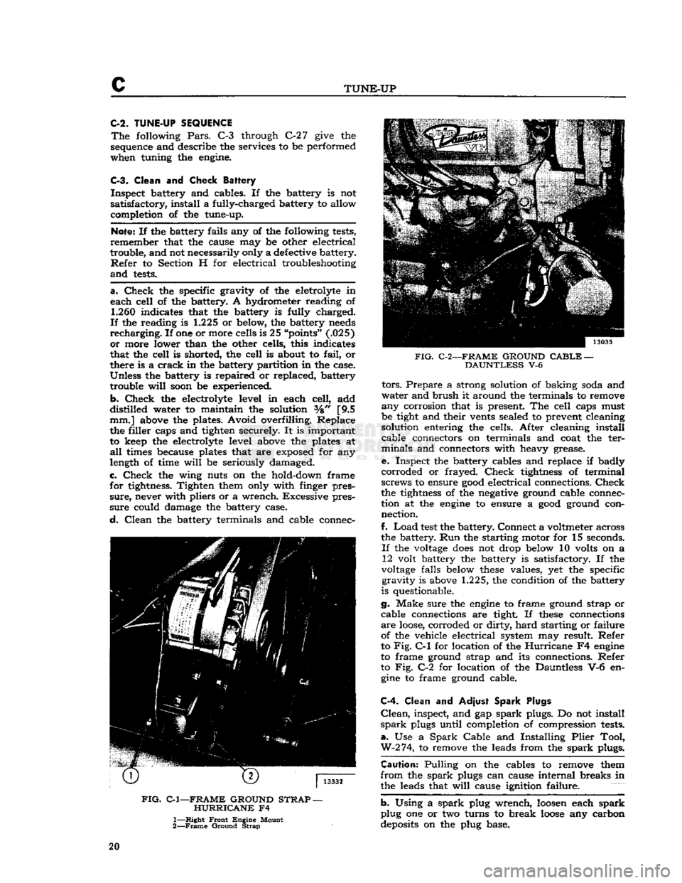
Make sure the engine to frame ground strap or
cable connections are tight. If
these
connections
are
loose,
corroded or dirty,
hard
starting or failure
of the vehicle electrical system may result. Refer
to
Fig.
C-l
for location of the
Hurricane
F4 engine
to frame ground strap and its connections. Refer to Fig. C-2 for location of the Dauntless V-6 en gine to frame ground cable.
C-4.
Clean and
Adjust
Spark Plugs
Clean,
inspect, and gap
spark
plugs. Do not install
spark
plugs until completion of compression tests.
a.
Use a
Spark
Cable
and Installing
Plier
Tool,
W-2
74,
to remove the leads from the
spark
plugs.
Caution:
Pulling on the cables to remove them
from
the
spark
plugs can cause internal breaks in
the leads that
will
cause ignition failure.
b.
Using a
spark
plug wrench, loosen each
spark
plug one or two turns to break
loose
any carbon
deposits on the plug base. 20
Page 31 of 376
'Jeep'
UNIVERSAL
SERIES
SERVICE
MANUAL
C
FIG.
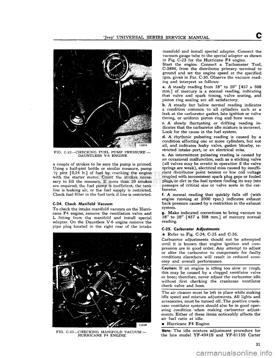
C-22—-CHECKING
FUEL
PUMP
PRESSURE
—
DAUNTLESS
V-6
ENGINE a
couple of strokes to be sure the pump is primed.
Using
a half-pint
bottle
or similar measure, pump
Vi
pint [0,24 It] of fuel by cranking the
engine
with
the starter motor. Count the strokes neces
sary
to
fill
the measure. If more than 20 strokes
are
required, the fuel pump is inefficient, the tank
line is leaking air, or the fuel supply is restricted.
Check
fuel filter in the fuel tank if line is restricted.
C-24.
Check Manifold Vacuum
To
check the intake manifold vacuum on the
Hurri
cane F4 engine, remove the ventilation valve and
L
fitting from the manifold and install special adapter. On the Dauntless V-6
engine
remove the
pipe plug located in the right
rear
of the intake
FIG.
C-23—CHECKING MANIFOLD VACUUM
—
HURRICANE
F4
ENGINE
manifold and install special adapter. Connect the
vacuum
gauge
tube to the special adapter as shown
in
Fig. C-23 for the
Hurricane
F4 engine.
Start
the engine. Connect a Tachometer
Tool,
C-3896,
from the distributor
primary
terminal to ground and set the
engine
speed at the specified
rpm.
given in Par. C-30. Observe the vacuum
read
ing and interpret as follows:
a.
A steady reading from 18" to 20" [457 a 508
mm.] of mercury is a normal reading, indicating
that valve and
spark
timing, valve seating, and
piston ring sealing are all satisfactory.
b. A steady but below normal reading indicates
a
condition common to all cylinders such as a
leak
at the carburetor gasket, late ignition or valve
timing, or uniform piston ring and bore wear.
c.
A slowly fluctuating or drifting reading in dicates that the carburetor idle mixture is incorrect
Look
for the cause in the fuel system.
d.
A rhythmic pulsating reading is caused by a
condition affecting one or more cylinders, but not
all,
and indicates leaky valve, gasket blowby, re
stricted intake port, or an electrical miss.
e. An intermittent pulsating reading is caused by
an
occasional malfunction, such as a sticking valve
(all
valves may be
erratic
in operation if the valve
springs are weak), electrical miss caused by insuffi
cient distributor point tension or low coil
voltage
coupled with inconsistent
spark
plug
gaps
or fouled
plugs, or
dirt
in the fuel system finding its way into
passages of
critical
size or valve
seats
in the
car
buretor.
f.
A normal reading that quickly falls off (with
engine
running at
2000
rpm.) indicates exhaust
back
pressure caused by a restriction in the exhaust
system.
g.
Make indicated corrections to bring vacuum to 18" to 20" [457 a 508 mm.] of mercury normal
reading.
C-25.
Carburetor Adjustments
•
Refer to Fig. C-24, C-25 and C-26.
Carburetor
adjustments should not be attempted
until
it is known that
engine
ignition and com
pression are in
good
order. Any attempt to adjust
or
alter the carburetor to compensate for faulty conditions elsewhere
will
result in reduced econ
omy and overall performance.
Caution:
If an
engine
is idling too slow or rough,
this may be caused by a
clogged
ventilator valve
or
hose;
therefore, never adjust the carburetor idle
without first checking the crankcase ventilator
check valve and
hose.
The
air cleaner must be left in place while making
idle speed and mixture adjustments. All lights and accessories, must be turned off. The positive
crank
case ventilator system should also be in
good
oper
ating condition when making carburetor adjust ments.
Either
of
these
items noticeably affects the
air
fuel ratio at idle.
•
Hurricane
F4 Engine.
Note:
The idle mixture adjustment procedure for
the late model
YF-4941S
and
YF-6115S
Carter
31
Page 41 of 376
'Jeep*
UNIVERSAL SERIES
SERVICE
MANUAL
D
insulator
mountings attached to the frame side
rail
brackets. The
rear
of the engine-transmission
assembly is supported by a rubber insulator
mounting under the
rear
of the transmission on
the frame center cross member.
This
cross member
is bolted to the frame side
rails
so that it can be
dropped when removing the transmission or engine-
transmission
assembly. The rubber insulators allow
free side and vertical oscillation to effectively
neutralize
engine
vibration at the source.
The
rubber
insulator mountings should be inspected
for separation and deterioration by jacking the
power plant away from the frame, near the sup
ports. Vibration cannot be effectively absorbed by
separated or worn insulators. They should be re placed if faulty.
D-4.
Engine
Ground
Strap
To
be sure of an
effective
ground for the electrical
circuits,
a ground strap bridges the right front
engine
support to the chassis. The connections of this strap must be kept clean and tight for proper
operation of the electrical system.
D-5. ENGINE REMOVAL
Should
the
engine
require overhauling, it is neces
sary
to remove it from the vehicle. The following procedure covers removal of the
engine
only.
The
engine, transmission and transfer case may be
removed as a unit by removing (in addition to the following procedure) the radiator guard and the
access plates in the floor pan.
a.
Drain
the cooling system by opening the
drain
cocks at the
bottom
of the radiator and lower right
side of the cylinder block.
b.
Disconnect the battery at the positive terminal
to avoid the possibility of short
circuit.
c. Remove the air cleaner horn from the carburetor
and
disconnect the breather
hose
at the oil filler
pipe.
d.
Disconnect the carburetor choke and throttle controls by loosening the clamp
bolts
and set
screws.
e. Disconnect the fuel-tank-to-fuel-pump line at the fuel pump by unscrewing the connecting nut.
f- Plug the fuel line to prevent fuel leakage.
g. Remove the radiator and radiator grille support
rods.
h. Remove the upper and lower radiator
hoses
by
loosening the
hose
clamps and slipping the clamps
back
on the
hose.
If so equipped, remove the heater
hoses
(one to the water pump, one to the
rear
of
the cylinder head) in the same manner.
i.
Remove the four
bolts
from the fan hub and re
move
the fan hub and fan blades.
j.
Remove the four radiator attaching screws. Re
move
the radiator and shroud as one unit, k. Remove the starting motor cables. Remove the
starting
motor.
I.
Disconnect the wires from the alternator or
generator. Disconnect the ignition
primary
wire
at the ignition coil.
NOTE:
ON
ENGINES EQUIPPED WITH EX
HAUST
EMISSION CONTROL, REMOVE THE
AIR
PUMP,
AIR
DISTRIBUTION
MANI
FOLD,
AND
ANTI-BACKFIRE (DIVERTER)
VALVE.
SEE SECTION
Fl
FOR PROCEDURE.
m.
Disconnect the oil pressure and temperature
sending unit wires at the units.
n.
Disconnect the exhaust pipe at the exhaust
manifold by removing the stud nuts.
o.
Disconnect the
spark
plug cables at the plugs
and
remove the cable bracket from the rocker arm cover stud.
p.
Remove the rocker arm cover by removing the
attaching stud nuts.
q.
Attach a lifting bracket to the
engine
using
existing head bolt locations. Be sure the
bolts
selected
will
hold the
engine
with the weight
balanced.
Attach lifting bracket to a boom hoist,
or
other lifting device, and take up all slack,
r.
Remove the two nuts and
bolts
from each front
engine
support. Disconnect the
engine
ground strap.
Remove the
engine
supports.
Lower
the
engine
slightly to permit access to the two top
bolts
on
the flywheel housing.
s. Remove the
bolts
which attach the flywheel
housing to the engine.
t.
Pull
the
engine
forward, or
roll
the vehicle back
wards,
until the clutch clears the flywheel housing.
Lift
the
engine
from the vehicle.
D-6. ENGINE DISASSEMBLY
Engine
disassembly is presented in the sequence to be followed when the
engine
is to be completely
overhauled after removal from the vehicle. Some
of the operations of the procedure are also ap
plicable
separately with the
engine
in the vehicle,
provided
that wherever necessary the part of the
engine
to be worked on is first made accessible by
removal
of
engine
accessories or other parts.
When
the disassembly operations are performed
with
the
engine
out of the vehicle, it is assumed,
in
this procedure, that all of the accessories have been removed
prior
to starting the disassembly
and
the oil has been drained.
In
addition to the instructions covering operations
for disassembling the
engine
out of the vehicle,
special
instructions are given to cover different
operations required when disassembly is
done
with the
engine
installed.
During
disassembly operations, the
engine
should
be mounted in a suitable
engine
repair
stand. Where
practicable,
modify or adapt an existing repair
stand
as necessary to accommodate the engine. If
an
engine
repair stand is not used, take care to
perform
disassembly operations in a manner that
will
protect personnel against an accident and the
engine
and its parts against damage.
NOTE:
If the
engine
is being disassembled because
of possible valve failure, check the valve tappet
clearance
before disassembly. Improper valve
clearance
could be the possible cause of valve
failure,
indicating a need for more frequent valve
checks and adjustments. 41
Page 70 of 376
D
HURRICANE
F4
ENGINE
D-112.
SERVICE
DIAGNOSIS
Poor
Fuel
Economy Ignition Timing Slow or Spark Advance Stuck
Carburetor
Float High
Accelerator Pump Not Properly Adjusted
High
Fuel
Pump Pressure
Fuel
Leakage
Leaky
Fuel
Pump Diaphragm
Loose Engine Mounting Causing High
Fuel
Level
in
Carburetor
Low
Compression Valves Sticking
Spark
Plugs Bad
Spark
Plug Cables Bad Weak
Coil
or Condenser Improper Valve Tappet Clearance
Carburetor
Air Cleaner Dirty
High Oil Level in Air Cleaner Dragging Brakes
Front
Wheels Out of Alignment
Tires
Improperly Inflated Inaccurate Odometer
Faulty
Fuel
Tank
Cap
Clogged
Muffler or Bent Exhaust Pipe
Lack
of Power
Low
Compression Ignition System (Timing Late)
Improper Functioning Carburetor or
Fuel
Pump
Fuel
Lines
Clogged
Air
Cleaner Restricted
Engine Temperature High Improper Tappet Clearance
Sticking Valves Valve Timing Late
Leaky
Gaskets
Muffler
Clogged
Bent Exhaust Pipe
Defective
Spark Plugs—Clean or Replace
Defective
Breaker Points—Replace
Points
Incorrect Breaker Point Gap—Reset
Points
Defective
Condenser or Coil—Replace
Loose Electrical Connections—Locate and Tighten
Broken Valve Spring—Replace Spring Broken Piston or Rings—Replace
Defective
Head Gasket—Replace Gasket
Cracked
Distributor Cap—Replace Cap
Low
Compression
Leaky
Valves
Poor Piston Ring Seal Sticking Valves
Valve Spring Weak or Broken
Cylinder
Scored or Worn
Tappet Clearance Incorrect
Piston Clearance too Large
Leaky
Cylinder Head Gasket
Burned Valves and
Seats
Sticking Valves or too Loose in Guides Improper Timing
Excessive Carbon Around Valve Head and Seat Overheating
Valve Spring Weak or Broken Burned Valves and Seats—Continued
Valve Tappet Sticking
Valve Tappet Clearance Incorrect
Clogged
Exhaust System
Valves Sticking Warped Valve Improper Tappet Clearance
Carbonized or Scored Valve
Stems
Insufficient Clearance Valve Stem to Guide
Weak or Broken Valve Spring Valve Spring Cocked Contaminated Oil
Overheating Inoperative Cooling System
Thermostat Inoperative Improper Ignition Timing
Improper Valve Timing
Excessive Carbon Accumulation
Fan
Belt too Loose
Clogged
Muffler or Bent Exhaust Pipe
Oil
System Failure
Scored or Leaky Piston Rings
Popping-Spitting-Detonation
Improper Ignition
Improper Carburetion
Excessive Carbon
Deposit
in Combustion
Cham
bers
Poor Valve Seating Sticking Valves
Broken Valve Spring Tappets Adjusted too Close
Spark
Plug Electrodes Burned
Water or Dirt in
Fuel
Clogged
Lines Improper Valve Timing
Excessive Oil Comsumption Piston Rings Stuck in Grooves, Worn or Broken Piston Rings Improperly Fitted or Weak Piston Ring Oil Return
Holes
Clogged
Excessive Clearance, Main and Connecting Rod
Bearings
Oil
Leaks at Gaskets or Oil Seals
Excessive Clearance, Valve Stem to Valve Guide (Intake)
Cylinder
Bores Scored, Out-of-Round or Tapered Too Much Clearance, Piston to Cylinder Bore
Misaligned Connecting Rods
High Road
Speeds
or Temperature
Crankcase
Ventilator Not Operating
Bearing Failure
Crankshaft
Bearing Journal Out-of-Round
Crankshaft
Bearing Journal Rough
Lack
of Oil
Oil
Leakage
Dirty
Oil
Low
Oil Pressure or Oil Pump Failure
Drilled
Passages
in Crankcase or Crankshaft
Clogged
Oil
Screen Dirty Connecting Rod Bent 70
Page 102 of 376
![JEEP CJ 1953 Service Manual
Dl
DAUNTLESS
V-6
ENGINE
FIG.
Dl-41—WATER
PUMP
AND
TIMING CHAIN COVER BOLT LOCATION
Cover
Bolts
alternately and evenly 8 to 12 lb-ft. [1,10 a 1,66
kg-m.].
Dl-88.
Install
Cranksh](/img/16/57040/w960_57040-101.png "JEEP CJ 1953 Service Manual
Dl
DAUNTLESS
V-6
ENGINE
FIG.
Dl-41—WATER
PUMP
AND
TIMING CHAIN COVER BOLT LOCATION
Cover
Bolts
alternately and evenly 8 to 12 lb-ft. [1,10 a 1,66
kg-m.].
Dl-88.
Install
Cranksh")
Dl
DAUNTLESS
V-6
ENGINE
FIG.
Dl-41—WATER
PUMP
AND
TIMING CHAIN COVER BOLT LOCATION
Cover
Bolts
alternately and evenly 8 to 12 lb-ft. [1,10 a 1,66
kg-m.].
Dl-88.
Install
Crankshaft
Vibration
Damper
a.
Lubricate
the vibration damper hub
before
in
stallation to prevent
damage
to the crankshaft
front oil seal during installation and when the
engine
is first started.
b.
Install
the vibration damper on the crankshaft.
Secure it with its attaching flat washer and screw.
Torque
the screw to a minimum of 140 lb-ft.
[19,35
kg-m.].
Dl-89.
Install
Crankshaft Pulley
Secure the crankshaft pulley to the crankshaft
vibration
damper with six screws. Torque screws 18 to 25 lb-ft. [2,5 a 3,4 kg-m.].
Dl-90.
Install
Oil
Level
Dipstick
Insert
oil level dipstick
into
the dipstick tube.
Dl-91.
Install
Oil
Pressure Sending Unit
Install
oil pressure sending unit in cylinder block.
Connect electrical wiring harness to unit.
Dl-92.
Install Starting Motor
Secure starting motor and
solenoid
assembly to
the flywheel housing and cylinder block with two attaching screws. Torque screw, which attaches this
assembly to the flywheel housing, 30 to 40 lb-ft. [4,1 a 5,5 kg-m.]. Torque screw, which attaches
bracket
to cylinder block, 10 to 12 lb-ft. [1,4 a 1,7 kg-m.].
Dl-93.
Install
Oil
Filter
Install
a new oil filter
element
at oil filter nipple,
at
left
side
of timing chain cover. Torque 10 to 15 lb-ft. [1,38 a 2,07 kg-m.].
D1-94. Install Water Pump
Be
certain that mating surfaces of the water pump
and
timing chain cover are clean.
Install
a new
gasket
on the pump flange. Secure the pump and
alternator adjustment bracket to the cover with
nine attaching bolts. Torque
bolts
6 to 8 lb-ft. [0,83 a 1,10 kg-m.]. Refer to Fig. Dl-41.
D1-9S.
Install
Cooling Fan
Secure the cooling fan, fan hub, and fan drive
pulley to the water pump shaft
flange
with four
attaching screws. Torque screws 17 to 23 lb-ft. [2,35 a 3,18 kg-m.].
Dl-96.
Install
Alternator
and Fan
Belt
Mount the alternator and bracket assembly on
right
cylinder head with two attaching screws.
Torque
screws 30 to 40 lb-ft. [4,1 a 5,5 kg-m.].
Fasten
the alternator
loosely
to its adjustment
bracket
with attaching flat washer and nut.
Install
the fan
belt
on its pulleys. Pivot the alternator
outward,
away from cylinder block, to apply fan
belt
tension. Adjust fan
belt
tension to 80 lb. [36,2 kg.];
tighten
alternator-to-adjustment bracket
nut to secure adjustment
setting.
Connect wiring
harness to alternator.
Dl-97.
Install
Fuel Pump
Install
two mounting
bolts
and new
gasket
on
flange
of fuel pump. Secure pump to timing chain cover with screws; torque screws 17 to 23 lb-ft. [2,35 a 3,8 kg-m.]. Connect
output
fuel line to
pump.
Dl-98.
Install Exhaust Manifold
Secure each of two exhaust manifolds to corre
sponding cylinder head with five attaching screws,
and
one nut. Torque screws and nut 15 to 20 lb-ft. [2,07 a 2,8 kg-m.]. See Fig. Dl-42.
Dl-99.
Install Distributor
Insert
distributor drive gear
into
distributor mount-
FIG.
Dl-42—EXHAUST
MANIFOLD INSTALLATION
1—Torque
Bolts—15
to 20
lb-ft.
[2,07 a 2,8
kg-m.]
102
Page 104 of 376
Dl
DAUNTLESS
V-6
ENGINE
e.
Connect electrical wiring harness to coolant
temperature sending unit. Connect two distributor leads to ignition coil. Connect fuel line
between
fuel pump and carburetor, vacuum
hose
between
distributor and carburetor, and crankcase vent
hose
to intake manifold
below
rear
of carburetor.
FIG.
D1-46—-INTAKE
MANIFOLD
INSTALLATION
1—Long Bolt 2—Open Bolt Hole
Dl-102.
ENGINE INSTALLATION
Install
the
engine
in the vehicle in the following
procedure listed
below:
a.
Attach suitable sling to
engine
lifting
eyes
and,
using a hoist, lift the
engine
from blocks or
engine
stand.
b. When
engine
is free of the stand lower it slowly
into
the
engine
compartment of the vehicle.
Note:
The
engine
and transmission must be lined
up to
engage
the main shaft and clutch plate spline
while sliding the
engine
rearward
into
the mounting
position.
c.
Install
and tighten up
bolts
securing
engine
to
flywheel housing.
d.
Install
and tighten front
engine
mounting bolts.
e.
Remove sling from the
engine.
I.
Connect exhaust pipes to right and
left
engine
manifolds.
g. Connect choke cable support bracket to
car
buretor.
h.
Connect
engine
fuel
hoses
and fuel lines at right
frame
rail.
I.
Connect fuel lines.
j.
Mount
engine
starter motor assembly to
engine.
k.
Connect battery cable and wiring to
engine
starter
motor.
I.
Connect
engine
wiring harnesses to connectors
located on
engine
firewall.
Note:
On
engines
equipped with exhaust emission
control, replace the air pump, air distributor mani
fold, and anti-backfire (gulp) valve. See Section F2.
m. Replace radiator, and secure with bolts,
n.
Replace and tighten right and
left
radiator sup
port rods.
0. Connect upper and lower radiator
hoses
to the
engine.
p. Connect alternator wiring harness from connec
tor at regulator,
q.
Replace air cleaner.
r.
Connect battery ground cable from the battery
to the
engine
and the
engine
ground strap,
s.
Replace the hood.
After
the
engine
is installed in the vehicle,
fill
radiator
with coolant and
engine
with oil (Refer to
Lubrication
Section B), then perform an
engine
Tune-up
and road
test
(Refer to Tune-up Sec
tion C).
Dl-103.
FINAL IN-VEHICLE ADJUSTMENTS
a.
Clean
battery terminals and check battery.
b.
Check
ignition wires and connections.
c. Service carburetor air cleaner.
d.
Service positive crankcase ventilation valve.
e.
Check
fuel lines.
f. Gap and install new
spark
plugs.
g.
Check
distributor
points
and capacitor; replace
if
necessary.
h.
Check
ignition (distributor) timing; reset if
necessary. 1.
Check
carburetor adjustments; reset if necessary,
j.
With
engine
fully warmed up, tighten cylinder
head and manifold
bolts
and nuts to specified
torque.
Check
cylinder head
gaskets
and
bolts
for
air
or coolant leaks.
Note:
Tightness of cylinder head
bolts
should be
checked and corrected after 500 miles [800 km.]
of normal operation and again at 1000 miles [1600
km.].
k.
Check
fan belt tension; adjust if necessary.
I.
Check
for and correct any oil leak, fuel leak or
coolant leak. 104
Page 105 of 376
'Jeep'
UNIVERSAL
SERIES SERVICE
MANUAL
Dl
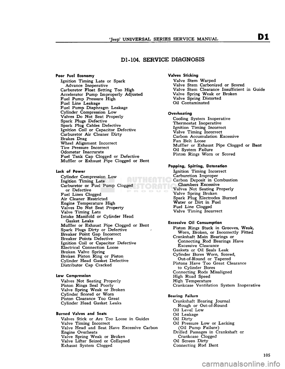
Dl-104.
SERVICE
DIAGNOSIS
Poor Fuel Economy
Ignition Timing Late or Spark Advance Inoperative
Carburetor
Float Setting Too High
Accelerator Pump Improperly Adjusted
Fuel
Pump Pressure High
Fuel
Line
Leakage
Fuel
Pump Diaphragm Leakage
Cylinder
Compression Low
Valves Do Not Seat Properly
Spark
Plugs
Defective
Spark
Plug Cables
Defective
Ignition
Coil
or Capacitor
Defective
Carburetor
Air Cleaner Dirty
Brakes
Drag
Wheel Alignment Incorrect
Tire
Pressure Incorrect Odometer Inaccurate
Fuel
Tank
Cap Clogged or
Defective
Muffler or Exhaust Pipe Clogged or Bent
Lack
of
Power
Cylinder
Compression Low
Ingitdon Timing Late
Carburetor
or
Fuel
Pump Clogged or
Defective
Fuel
Lines Clogged
Air
Cleaner Restricted
Engine Temperature High Valves Do Not Seat Property
Valve
Timing Late Intake Manifold or Cylinder Head
Gasket Leaks
Muffler or Exhaust Pipe Clogged or Bent
Spark
Plugs Dirty or
Defective
Breaker
Point Gap Incorrect
Breaker
Points
Defective
Ignition
Coil
or Capacitor
Defective
Electrical
Connection Loose
Broken
Valve Spring
Broken
Piston Ring or Piston
Cylinder
Head Gasket
Defective
Distributor Cap Cracked
Low
Compression
Valves Not Seating Properly Piston Rings Seal Poorly
Valve
Spring Weak or Broken
Cylinder
Scored or Worn
Piston Clearance Too Great
Cylinder
Head Gasket Leaks
Burned
Valves and
Seats
Valves Stick or Are Too Loose in Guides
Valve
Timing Incorrect
Valve
Head and Seat Have Excessive Carbon
Engine Overheats
Valve
Spring Weak or Broken
Valve
Lifter Seized or Collapsed
Exhaust
System Clogged
Valves Sticking
Valve
Stem Warped
Valve
Stem Carbonized or Scored
Valve
Stem Clearance Insufficient in Guide
Valve
Spring Weak or Broken
Valve
Spring Distorted
Oil
Contaminated
Overheating
Cooling System Inoperative
Thermostat Inoperative Ignition Timing Incorrect
Valve
Timing Incorrect
Carbon
Accumulation Excessive
Fan
Belt Loose
Muffler or Exhaust Pipe Clogged or Bent
Oil
System Failure
Piston Rings Worn or Scored
Popping,
Spitting,
Detonation
Ignition Timing Incorrect
Carburetion
Improper
Carbon
Deposit
in Combustion
Chambers Excessive
Valves Not Seating Properly
Valve
Spring Broken
Spark
Plug Electrodes Burned
Water or Dirt in
Fuel
Fuel
Line
Clogged
Valve
Timing Incorrect
Excessive
Oil
Consumption
Piston Rings Stuck in Grooves, Weak,
Worn,
Broken, or Incorrectly Fitted
Crankshaft
Main Bearings or
Connecting Rod Bearings Have
Excessive Clearance
Gaskets or Oil Seals
Leak
Cylinder
Bores Worn, Scored,
Out-of-Round or Tapered
Pistons Have Too Great Clearance to Cylinder Bores
Connecting Rods Misaligned High Road Speed
High Temperature
Crankcase
Ventilation System Inoperative
Bearing Failure
Crankshaft
Bearing Journal Rough or Out-of-Round
Oil
Level Low
Oil
Leakage
Oil
Dirty
Oil
Pressure Low or Lacking
(Oil
Pump Failure)
Drilled
Passages
in Crankshaft or
Crankcase
Clogged
Oil
Screen Dirty
Connecting Rod Bent 105