battery JEEP COMPASS 2013 1.G User Guide
[x] Cancel search | Manufacturer: JEEP, Model Year: 2013, Model line: COMPASS, Model: JEEP COMPASS 2013 1.GPages: 116, PDF Size: 2.71 MB
Page 54 of 116
STEERING WHEEL AUDIO CONTROLS
•The steering wheel audio controls are
located on the rear surface of the steer-
ing wheel.
Right Switch
•Press the switch up or down to increase
or decrease the volume.
• Press the button in the center to change modes AM/FM/CD/SAT.
Left Switch
• Press the switch up or down to search for the next listenable station or select the
next or previous CD track.
• Press the button in the center to select the next preset station (radio) or to change CDs if equipped with a CD Changer.
iPod®/USB/MP3 CONTROL
• There are many ways to play music from iPod®/MP3 players or USB devices
through your vehicle's sound system.
• The remote USB port, located within the front storage area, allows you to plug an iPod
®into the vehicle's sound system.
• Non-Touch-Screen Radios: To hear audio from devices connected to the USB port, press the “AUX” button on the radio faceplate.
• Touch-Screen Radios: To hear audio from devices connected to the USB port, press the “MEDIA” hard-key, then touch the “AUX” or “iPod
®” soft-key.
• When connected to this feature: •
The iPod®can be controlled using the
radio buttons to Play, Browse, and List
the iPod
®or external devices contents.
• The iPod®battery charges when
plugged into the USB port (if sup-
ported by the specific audio device).
• Compatible iPod
®devices may also
be controllable using voice commands. Refer to the Owner's Manual on the DVD
for details.
ELECTRONICS
52
Page 64 of 116
Auto Door Lock
• To have the doors lock automatically when the vehicle’s speed exceeds 15 mph(24 km/h):
• Enter your vehicle and close all the doors.
• Cycle the ignition switch between LOCK and ON and then back to LOCK fourtimes, ending up in the LOCK position (do not start the engine).
• Press the power door LOCK switch to lock the doors. A single chime will indicate that programming is complete.
Sound Horn With Lock
• To turn the horn chirp on or off when the doors are locked: • Press the LOCK button for at least 4 seconds, but no longer than 10 seconds.
Then, press the PANIC button while still holding the LOCK button.
• Release both buttons at the same time.
Flashing Lights With Lock
• The turn signal lights flashing, when the doors are locked or unlocked, feature can be turned on or off. To turn this feature on or off:• Press and hold the UNLOCK button for at least 4 seconds, but no longer than
10 seconds. Then, press and hold the LOCK button while still holding the
UNLOCK button.
• Release both buttons at the same time.
UNIVERSAL GARAGE DOOR OPENER (HomeLink®)
• HomeLink®replaces up to three hand-held transmitters that operate devices such
as garage door openers, motorized gates, lighting or home security systems.
The HomeLink
®unit is powered by your vehicles 12 Volt battery.
• The HomeLink
®buttons that are located in the overhead console or sunvisor
designate the three different HomeLink®channels.
• The HomeLink
®indicator is located above the center button.
ELECTRONICS
62
Page 65 of 116
Before You Begin Programming HomeLink®
•Ensure that your vehicle is parked outside of the garage before you begin program-
ming.
•For efficient programming and accurate transmission of the radio-frequency signal,
it is recommended that a new battery be placed in the hand-held transmitter of the
device that is being programmed to the HomeLink
®system.
• Erase all channels before you begin programming. To erase the channels, place the ignition switch into the ON/RUN position, then press and hold the two outside
HomeLink
®buttons (I and III) for up 20 seconds or until the red indicator flashes.
NOTE:
Erasing all channels should only be performed when programming HomeLink
®for
the first time. Do not erase channels when programming additional buttons.
•
If you have any problems, or require assistance, please call toll-free 1–800–355–3515
or, on the Internet at www.HomeLink.com for information or assistance.
Programming A Rolling Code
• For programming Garage Door Openers that were manufactured after 1995. These Garage Door Openers can be identified by the “LEARN” or “TRAIN” button
located where the hanging antenna is attached to the Garage Door Opener. It is
NOT the button that is normally used to open and close the door. The name and
color of the button may vary by manufacturer.
• Place the ignition switch into the ON/RUN position.
• Place the hand-held transmitter 1 to 3 in (3 to 8 cm) away from the HomeLink
®
button you wish to program while keeping the HomeLink®indicator light in view.
• Simultaneously press and hold both the HomeLink
®button you want to program
and the hand-held transmitter button.
• Continue to hold both buttons and observe the indicator light. The HomeLink
®
indicator will flash slowly and then rapidly after HomeLink®has received the
frequency signal from the hand-held transmitter. Release both buttons after the
indicator light changes from slow to rapid.
•
At the garage door opener motor (in the garage), locate the “LEARN” or “TRAINING”
button. This can usually be found where the hanging antenna wire is attached to the
garage door opener motor. Firmly press and release the “LEARN” or “TRAINING”
button.
NOTE:
You have 30 seconds in which to initiate the next step after the LEARN button has
been pressed.
• Return to the vehicle and press the programmed HomeLink
®button twice
(holding the button for two seconds each time). If the device is plugged in and
activates, programming is complete.
ELECTRONICS
63
Page 83 of 116
JUMP-STARTING PROCEDURES
• If your vehicle has a discharged battery it can be jump-started using a set ofjumper cables and a battery in another vehicle or by using a portable battery
booster pack. Jump-starting can be dangerous if done improperly so please follow
the procedures in this section carefully.
NOTE:
When using a portable battery booster pack follow the manufacturer’s operating
instructions and precautions.
Preparations For Jump-Start
• The battery in your vehicle is located in the front of the engine compartment below the air intake duct. To access the battery remove the air intake duct by turning the
two finger screws, located on the radiator support.
1.
Set the parking brake, shift the auto-
matic transmission into PARK and turn
the ignition to LOCK.
2.Turn off the heater, radio, and all un-
necessary electrical accessories.
3.If using another vehicle to jump-start
the battery, park the vehicle within the
jumper cables reach, set the parking
brake and make sure the ignition is
OFF.
WHAT TO DO IN EMERGENCIES
81
Page 84 of 116
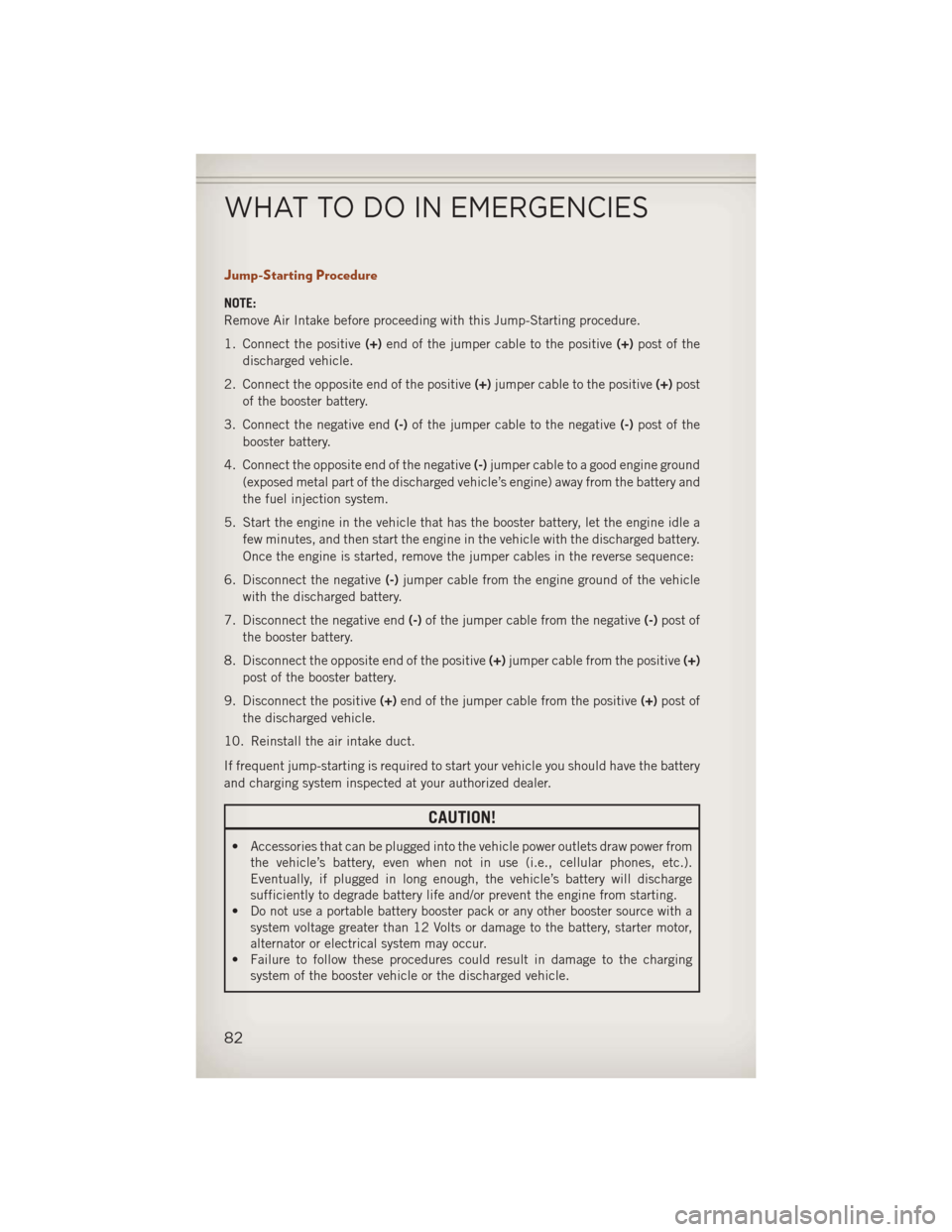
Jump-Starting Procedure
NOTE:
Remove Air Intake before proceeding with this Jump-Starting procedure.
1. Connect the positive(+)end of the jumper cable to the positive (+)post of the
discharged vehicle.
2. Connect the opposite end of the positive (+)jumper cable to the positive (+)post
of the booster battery.
3. Connect the negative end (-)of the jumper cable to the negative (-)post of the
booster battery.
4. Connect the opposite end of the negative (-)jumper cable to a good engine ground
(exposed metal part of the discharged vehicle’s engine) away from the battery and
the fuel injection system.
5. Start the engine in the vehicle that has the booster battery, let the engine idle a few minutes, and then start the engine in the vehicle with the discharged battery.
Once the engine is started, remove the jumper cables in the reverse sequence:
6. Disconnect the negative (-)jumper cable from the engine ground of the vehicle
with the discharged battery.
7. Disconnect the negative end (-)of the jumper cable from the negative (-)post of
the booster battery.
8. Disconnect the opposite end of the positive (+)jumper cable from the positive (+)
post of the booster battery.
9. Disconnect the positive (+)end of the jumper cable from the positive (+)post of
the discharged vehicle.
10. Reinstall the air intake duct.
If frequent jump-starting is required to start your vehicle you should have the battery
and charging system inspected at your authorized dealer.
CAUTION!
• Accessories that can be plugged into the vehicle power outlets draw power from the vehicle’s battery, even when not in use (i.e., cellular phones, etc.).
Eventually, if plugged in long enough, the vehicle’s battery will discharge
sufficiently to degrade battery life and/or prevent the engine from starting.
• Do not use a portable battery booster pack or any other booster source with a
system voltage greater than 12 Volts or damage to the battery, starter motor,
alternator or electrical system may occur.
• Failure to follow these procedures could result in damage to the charging
system of the booster vehicle or the discharged vehicle.
WHAT TO DO IN EMERGENCIES
82
Page 85 of 116
WARNING!
• Do not attempt jump-starting if the battery is frozen. It could rupture or explodeand cause personal injury.
•
Take care to avoid the radiator cooling fan whenever the hood is raised. It can start
anytime the ignition switch is on. You can be injured by moving fan blades.
• Remove any metal jewelry such as watch bands or bracelets that might make
an inadvertent electrical contact. You could be seriously injured.
• Batteries contain sulfuric acid that can burn your skin or eyes and generate
hydrogen gas which is flammable and explosive. Keep open flames or sparks
away from the battery.
• Do not allow vehicles to touch each other as this could establish a ground
connection and personal injury could result.
• Failure to follow this procedure could result in personal injury or property
damage due to battery explosion.
• Do not connect the cable to the negative post (-)of the discharged battery.
The resulting electrical spark could cause the battery to explode and could
result in personal injury.
SHIFT LEVER OVERRIDE
• If a malfunction occurs and the shift lever cannot be moved out of the PARK position, you can use the following procedure to temporarily move the shift lever:
• To access the shift lever override, locate and remove the removable plug in theright side of the shift lever housing.
• Firmly set the parking brake.
• Turn the ignition switch to the ACC or ON position without starting the engine.
• Press and maintain firm pressure on the brake pedal.
• Using a screwdriver or similar tool, press and hold the override tab through the access port on the center console.
• Move the shift lever into the NEUTRAL position.
• The vehicle may then be started in NEUTRAL.
• Reinstall the override cover.
WHAT TO DO IN EMERGENCIES
83
Page 94 of 116
Your authorized dealer will reset the oil change indicator message after completing
the scheduled oil change. If a scheduled oil change is performed by someone other
than your authorized dealer, the message can be reset by referring to the steps
described under “Electronic Vehicle Information Center (EVIC)/Oil Change Re-
quired” in “Understanding Your Instrument Panel” or under “Instrument Cluster
Description/Odometer/Trip Odometer” in “Understanding Your Instrument Panel” for
further information.
NOTE:
Under no circumstances should oil change intervals exceed 10,000 miles (16,000 km)
or twelve months, whichever comes first.
Once A Month Or Before A Long Trip:
• Check engine oil level
• Check windshield washer fluid level
• Check the tire inflation pressures and look for unusual wear or damage
• Check the fluid levels of the coolant reservoir, brake master cylinder, powersteering and fill as needed
• Check function of all interior and exterior lights
Required Maintenance Intervals.
Refer to the maintenance schedules on the following page for the required mainte-
nance intervals.
At Every Oil Change Interval As Indicated By Oil Change Indicator System:
• Change oil and filter
• Rotate the tires. Rotate at the first sign of irregular wear, even if it occurs before the oil
indicator system turns on.
• Inspect battery and clean and tighten terminals as required
• Inspect brake pads, shoes, rotors, drums, hoses and park brake
• Inspect engine cooling system protection and hoses
• Inspect exhaust system
• Inspect engine air cleaner if using in dusty or off-road conditions
MAINTAINING YOUR VEHICLE
92
Page 98 of 116
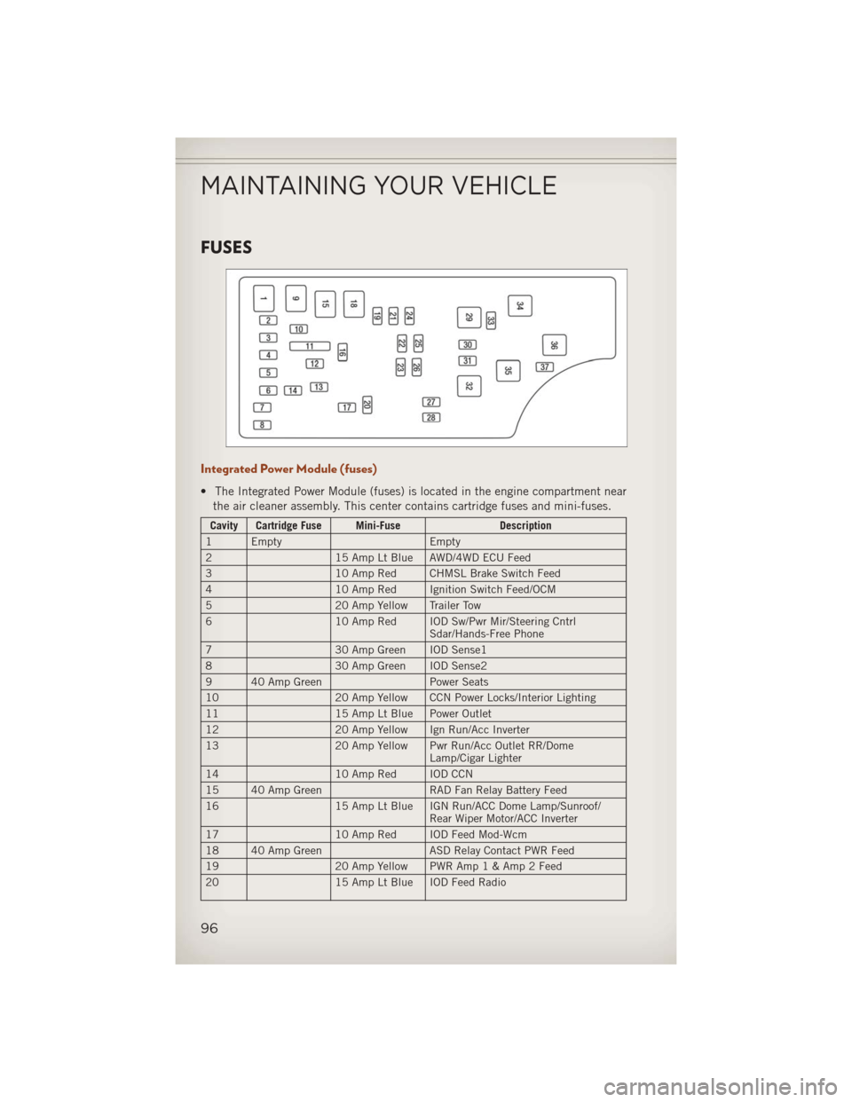
FUSES
Integrated Power Module (fuses)
• The Integrated Power Module (fuses) is located in the engine compartment nearthe air cleaner assembly. This center contains cartridge fuses and mini-fuses.
Cavity Cartridge Fuse Mini-Fuse Description
1 Empty Empty
2 15 Amp Lt Blue AWD/4WD ECU Feed
3 10 Amp Red CHMSL Brake Switch Feed
4 10 Amp Red Ignition Switch Feed/OCM
5 20 Amp Yellow Trailer Tow
6 10 Amp Red IOD Sw/Pwr Mir/Steering Cntrl
Sdar/Hands-Free Phone
7 30 Amp Green IOD Sense1
8 30 Amp Green IOD Sense2
9 40 Amp Green Power Seats
10 20 Amp Yellow CCN Power Locks/Interior Lighting
11 15 Amp Lt Blue Power Outlet
12 20 Amp Yellow Ign Run/Acc Inverter
13 20 Amp Yellow Pwr Run/Acc Outlet RR/Dome
Lamp/Cigar Lighter
14 10 Amp Red IOD CCN
15 40 Amp Green RAD Fan Relay Battery Feed
16 15 Amp Lt Blue IGN Run/ACC Dome Lamp/Sunroof/
Rear Wiper Motor/ACC Inverter
17 10 Amp Red IOD Feed Mod-Wcm
18 40 Amp Green ASD Relay Contact PWR Feed
19 20 Amp Yellow PWR Am p1&Amp2Feed
20 15 Amp Lt Blue IOD Feed Radio
MAINTAINING YOUR VEHICLE
96