fuel JEEP COMPASS 2015 1.G User Guide
[x] Cancel search | Manufacturer: JEEP, Model Year: 2015, Model line: COMPASS, Model: JEEP COMPASS 2015 1.GPages: 132, PDF Size: 21.94 MB
Page 10 of 132
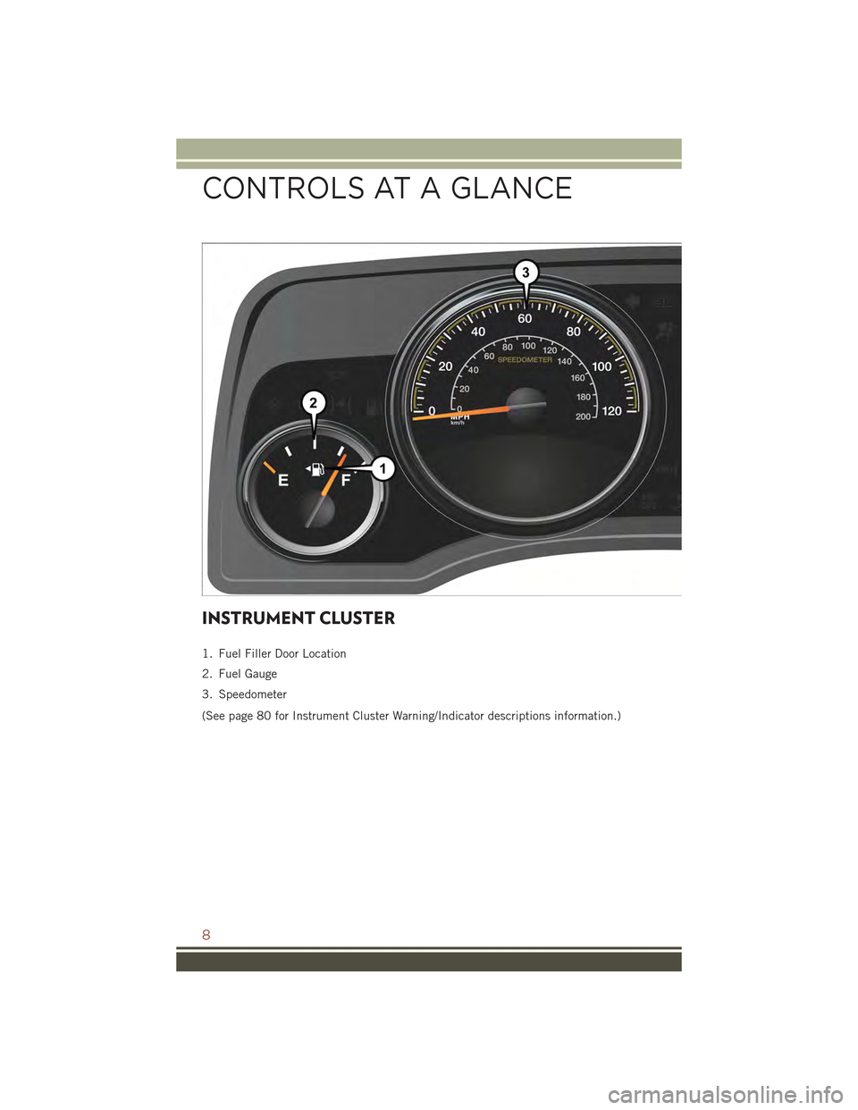
INSTRUMENT CLUSTER
1. Fuel Filler Door Location
2. Fuel Gauge
3. Speedometer
(See page 80 for Instrument Cluster Warning/Indicator descriptions information.)
CONTROLS AT A GLANCE
8
Page 33 of 132
CONTINUOUSLY VARIABLE AUTOMATIC
TRANSMISSION (CVT)
While conventional automatic transmissions typically have 4, 5 or 6 speeds, the
Continuously Variable Transmission (CVT) has an infinite number of speeds. This
allows it to adjust to exactly the right ratio to optimize performance and fuel
economy.
Under hard acceleration, you may hear more engine noise than with a conventional
transmission. The CVT may also occasionally feel like it is “shifting.” These
characteristics are perfectly normal and contribute to the CVT's efficiency.
SIX-SPEED AUTOMATIC TRANSMISSION
This electronically-controlled transmission provides a precise shift schedule. The
transmission electronics are self-calibrating; therefore, the first few shifts on a new
vehicle may be somewhat abrupt. This is a normal condition, and precision shifts will
develop within a few hundred miles (kilometers).
The transmission shift lever has only PARK, REVERSE, NEUTRAL, and DRIVE shift
positions. Manual shifts can be made using the Autostick®shift control. Moving the
shift lever to the left or right (-/+) while in the DRIVE position will manually select the
transmission gear, and will display the current gear in the instrument cluster as 6, 5,
4, 3, 2, 1.
Refer to your Owner’s Manual on the DVD for further information.
OPERATING YOUR VEHICLE
31
Page 62 of 132
SiriusXM Travel Link (Uconnect® 730N & Uconnect® 430N Only)
NOTE:
• SiriusXM Travel Link requires a subscription, sold separately after the five year
trial subscription included with your vehicle purchase.
• SiriusXM Travel Link is only available in the United States.
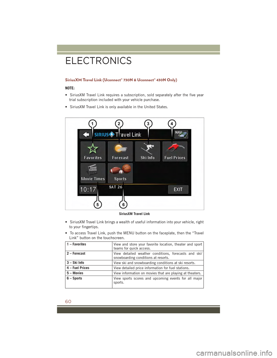
• SiriusXM Travel Link brings a wealth of useful information into your vehicle, right
to your fingertips.
• To access Travel Link, push the MENU button on the faceplate, then the “Travel
Link” button on the touchscreen.
1 – FavoritesView and store your favorite location, theater and sportteams for quick access.
2 – ForecastView detailed weather conditions, forecasts and ski/snowboarding conditions at resorts.
3 – Ski InfoView ski and snowboarding conditions at ski resorts.
4 – Fuel PricesView detailed price information for fuel stations.
5 – MoviesView information on movies that are playing at theaters.
6 – SportsView sports scores and upcoming events for all majorsports.
SiriusXM Travel Link
ELECTRONICS
60
Page 70 of 132
ELECTRONIC VEHICLE INFORMATION CENTER
(EVIC)
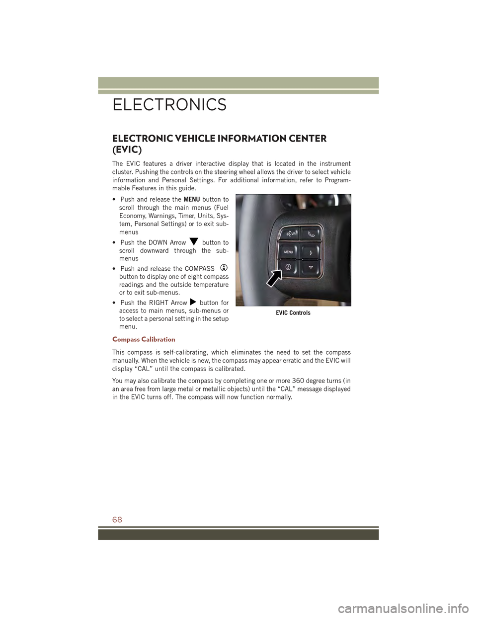
The EVIC features a driver interactive display that is located in the instrument
cluster. Pushing the controls on the steering wheel allows the driver to select vehicle
information and Personal Settings. For additional information, refer to Program-
mable Features in this guide.
• Push and release theMENUbutton to
scroll through the main menus (Fuel
Economy, Warnings, Timer, Units, Sys-
tem, Personal Settings) or to exit sub-
menus
• Push the DOWN Arrowbutton to
scroll downward through the sub-
menus
• Push and release the COMPASS
button to display one of eight compass
readings and the outside temperature
or to exit sub-menus.
• Push the RIGHT Arrowbutton for
access to main menus, sub-menus or
to select a personal setting in the setup
menu.
Compass Calibration
This compass is self-calibrating, which eliminates the need to set the compass
manually. When the vehicle is new, the compass may appear erratic and the EVIC will
display “CAL” until the compass is calibrated.
You may also calibrate the compass by completing one or more 360 degree turns (in
an area free from large metal or metallic objects) until the “CAL” message displayed
in the EVIC turns off. The compass will now function normally.
EVIC Controls
ELECTRONICS
68
Page 82 of 132
ROADSIDE ASSISTANCE
Dial toll-free 1-800-521-2779 for U.S. Residents or 1-800-363-4869 for Canadian
Residents.
• Provide your name, vehicle identification number, license plate number, and your
location, including the telephone number from which you are calling.
• Briefly describe the nature of the problem and answer a few simple questions.
• You will be given the name of the service provider and an estimated time of arrival.
If you feel you are in an “unsafe situation”, please let us know. With your consent,
we will contact local police or safety authorities.
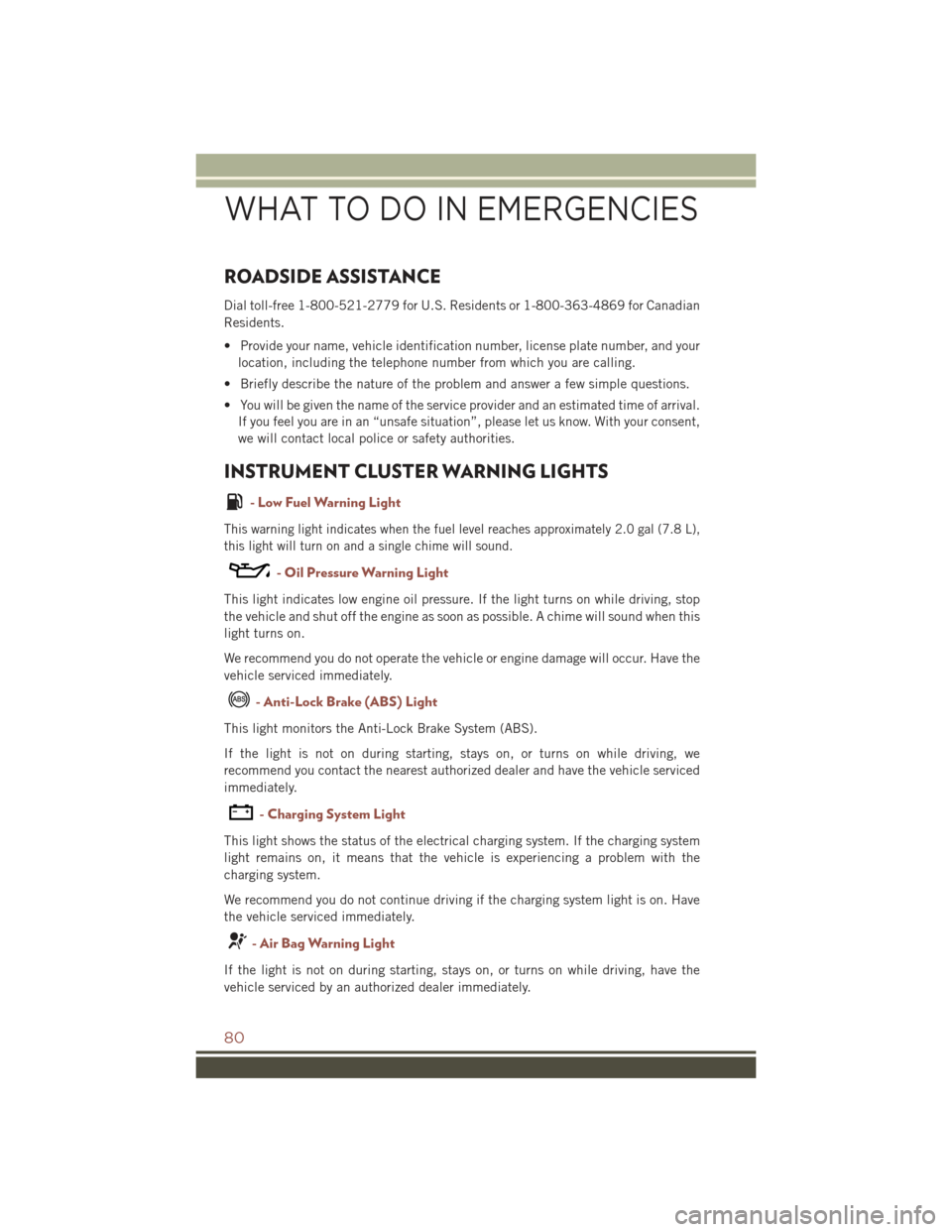
INSTRUMENT CLUSTER WARNING LIGHTS
- Low Fuel Warning Light
This warning light indicates when the fuel level reaches approximately 2.0 gal (7.8 L),
this light will turn on and a single chime will sound.
- Oil Pressure Warning Light
This light indicates low engine oil pressure. If the light turns on while driving, stop
the vehicle and shut off the engine as soon as possible. A chime will sound when this
light turns on.
We recommend you do not operate the vehicle or engine damage will occur. Have the
vehicle serviced immediately.
- Anti-Lock Brake (ABS) Light
This light monitors the Anti-Lock Brake System (ABS).
If the light is not on during starting, stays on, or turns on while driving, we
recommend you contact the nearest authorized dealer and have the vehicle serviced
immediately.
-ChargingSystemLight
This light shows the status of the electrical charging system. If the charging system
light remains on, it means that the vehicle is experiencing a problem with the
charging system.
We recommend you do not continue driving if the charging system light is on. Have
the vehicle serviced immediately.
- Air Bag Warning Light
If the light is not on during starting, stays on, or turns on while driving, have the
vehicle serviced by an authorized dealer immediately.
WHAT TO DO IN EMERGENCIES
80
Page 83 of 132
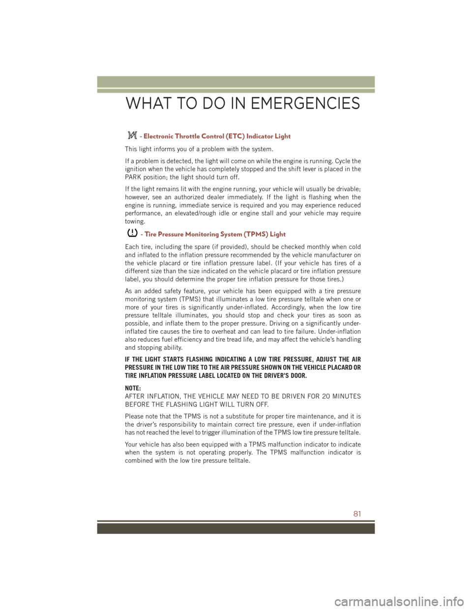
- Electronic Throttle Control (ETC) Indicator Light
This light informs you of a problem with the system.
If a problem is detected, the light will come on while the engine is running. Cycle the
ignition when the vehicle has completely stopped and the shift lever is placed in the
PARK position; the light should turn off.
If the light remains lit with the engine running, your vehicle will usually be drivable;
however, see an authorized dealer immediately. If the light is flashing when the
engine is running, immediate service is required and you may experience reduced
performance, an elevated/rough idle or engine stall and your vehicle may require
towing.
-TirePressureMonitoringSystem(TPMS)Light
Each tire, including the spare (if provided), should be checked monthly when cold
and inflated to the inflation pressure recommended by the vehicle manufacturer on
the vehicle placard or tire inflation pressure label. (If your vehicle has tires of a
different size than the size indicated on the vehicle placard or tire inflation pressure
label, you should determine the proper tire inflation pressure for those tires.)
As an added safety feature, your vehicle has been equipped with a tire pressure
monitoring system (TPMS) that illuminates a low tire pressure telltale when one or
more of your tires is significantly under-inflated. Accordingly, when the low tire
pressure telltale illuminates, you should stop and check your tires as soon as
possible, and inflate them to the proper pressure. Driving on a significantly under-
inflated tire causes the tire to overheat and can lead to tire failure. Under-inflation
also reduces fuel efficiency and tire tread life, and may affect the vehicle’s handling
and stopping ability.
IF THE LIGHT STARTS FLASHING INDICATING A LOW TIRE PRESSURE, ADJUST THE AIR
PRESSURE IN THE LOW TIRE TO THE AIR PRESSURE SHOWN ON THE VEHICLE PLACARD OR
TIRE INFLATION PRESSURE LABEL LOCATED ON THE DRIVER'S DOOR.
NOTE:
AFTER INFLATION, THE VEHICLE MAY NEED TO BE DRIVEN FOR 20 MINUTES
BEFORE THE FLASHING LIGHT WILL TURN OFF.
Please note that the TPMS is not a substitute for proper tire maintenance, and it is
the driver’s responsibility to maintain correct tire pressure, even if under-inflation
has not reached the level to trigger illumination of the TPMS low tire pressure telltale.
Your vehicle has also been equipped with a TPMS malfunction indicator to indicate
when the system is not operating properly. The TPMS malfunction indicator is
combined with the low tire pressure telltale.
WHAT TO DO IN EMERGENCIES
81
Page 86 of 132
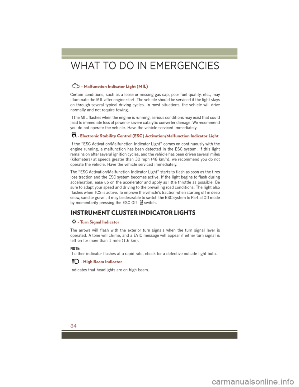
- Malfunction Indicator Light (MIL)
Certain conditions, such as a loose or missing gas cap, poor fuel quality, etc., may
illuminate the MIL after engine start. The vehicle should be serviced if the light stays
on through several typical driving cycles. In most situations, the vehicle will drive
normally and not require towing.
If the MIL flashes when the engine is running, serious conditions may exist that could
lead to immediate loss of power or severe catalytic converter damage. We recommend
you do not operate the vehicle. Have the vehicle serviced immediately.
-ElectronicStabilityControl(ESC)Activation/MalfunctionIndicatorLight
If the “ESC Activation/Malfunction Indicator Light” comes on continuously with the
engine running, a malfunction has been detected in the ESC system. If this light
remains on after several ignition cycles, and the vehicle has been driven several miles
(kilometers) at speeds greater than 30 mph (48 km/h), we recommend you do not
operate the vehicle. Have the vehicle serviced immediately.
The “ESC Activation/Malfunction Indicator Light” starts to flash as soon as the tires
lose traction and the ESC system becomes active. If the light begins to flash during
acceleration, ease up on the accelerator and apply as little throttle as possible. Be
sure to adapt your speed and driving to the prevailing road conditions. The light also
flashes when TCS is active. To improve the vehicle's traction when starting off in deep
snow, sand or gravel, it may be desirable to switch the ESC system to Partial Off mode
by momentarily pressing the ESC Offswitch.
INSTRUMENT CLUSTER INDICATOR LIGHTS
- Turn Signal Indicator
The arrows will flash with the exterior turn signals when the turn signal lever is
operated. A tone will chime, and a EVIC message will appear if either turn signal is
left on for more than 1 mile (1.6 km).
NOTE:
If either indicator flashes at a rapid rate, check for a defective outside light bulb.
- High Beam Indicator
Indicates that headlights are on high beam.
WHAT TO DO IN EMERGENCIES
84
Page 97 of 132
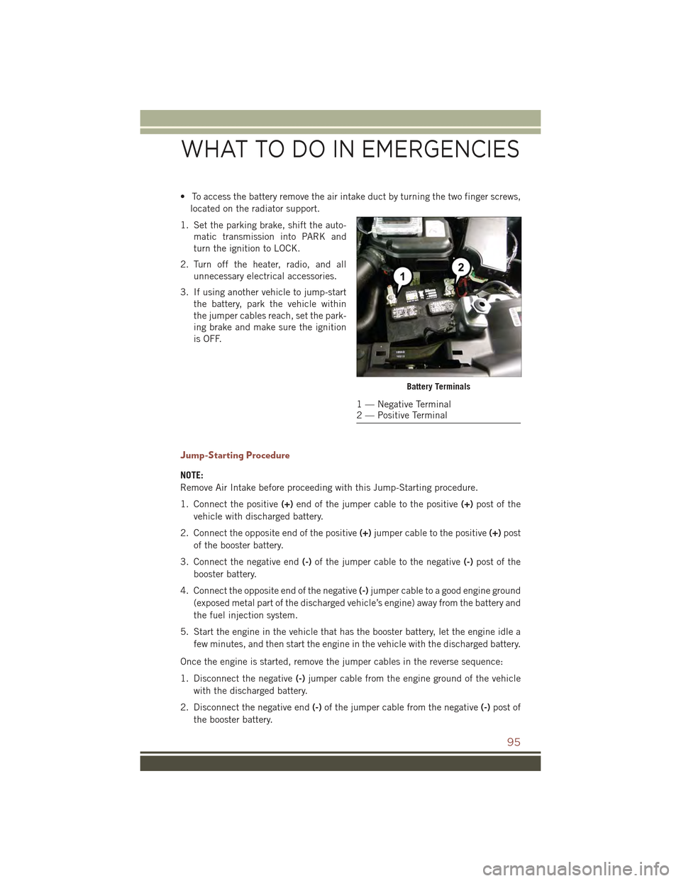
• To access the battery remove the air intake duct by turning the two finger screws,
located on the radiator support.
1. Set the parking brake, shift the auto-
matic transmission into PARK and
turn the ignition to LOCK.
2. Turn off the heater, radio, and all
unnecessary electrical accessories.
3. If using another vehicle to jump-start
the battery, park the vehicle within
the jumper cables reach, set the park-
ing brake and make sure the ignition
is OFF.
Jump-Starting Procedure
NOTE:
Remove Air Intake before proceeding with this Jump-Starting procedure.
1. Connect the positive(+)end of the jumper cable to the positive(+)post of the
vehicle with discharged battery.
2. Connect the opposite end of the positive(+)jumper cable to the positive(+)post
of the booster battery.
3. Connect the negative end(-)of the jumper cable to the negative(-)post of the
booster battery.
4. Connect the opposite end of the negative(-)jumper cable to a good engine ground
(exposed metal part of the discharged vehicle’s engine) away from the battery and
the fuel injection system.
5. Start the engine in the vehicle that has the booster battery, let the engine idle a
few minutes, and then start the engine in the vehicle with the discharged battery.
Once the engine is started, remove the jumper cables in the reverse sequence:
1. Disconnect the negative(-)jumper cable from the engine ground of the vehicle
with the discharged battery.
2. Disconnect the negative end(-)of the jumper cable from the negative(-)post of
the booster battery.
Battery Terminals
1 — Negative Terminal2 — Positive Terminal
WHAT TO DO IN EMERGENCIES
95
Page 108 of 132
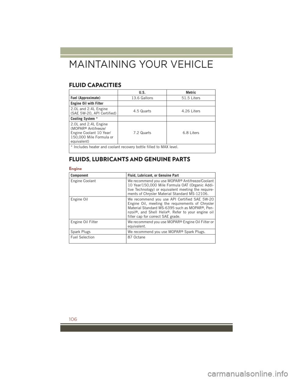
FLUID CAPACITIES
U.S.Metric
Fuel (Approximate)13.6 Gallons51.5 Liters
Engine Oil with Filter
2.0L and 2.4L Engine(SAE 5W-20, API Certified)4.5 Quarts4.26 Liters
Cooling System *
2.0L and 2.4L Engine(MOPAR®Antifreeze/Engine Coolant 10 Year/150,000 Mile Formula orequivalent)
7.2 Quarts 6.8 Liters
* Includes heater and coolant recovery bottle filled to MAX level.
FLUIDS, LUBRICANTS AND GENUINE PARTS
Engine
ComponentFluid, Lubricant, or Genuine Part
Engine CoolantWe recommend you use MOPAR®Antifreeze/Coolant10 Year/150,000 Mile Formula OAT (Organic Addi-tive Technology) or equivalent meeting the require-ments of Chrysler Material Standard MS-12106.
Engine OilWe recommend you use API Certified SAE 5W-20Engine Oil, meeting the requirements of ChryslerMaterial Standard MS-6395 such as MOPAR®,Pen-nzoil®, and Shell Helix®. Refer to your engine oilfiller cap for correct SAE grade.
Engine Oil Filter We recommend you use MOPAR®Engine Oil Filter orequivalent.
Spark Plugs We recommend you use MOPAR®Spark Plugs.
Fuel Selection87 Octane
MAINTAINING YOUR VEHICLE
106
Page 116 of 132
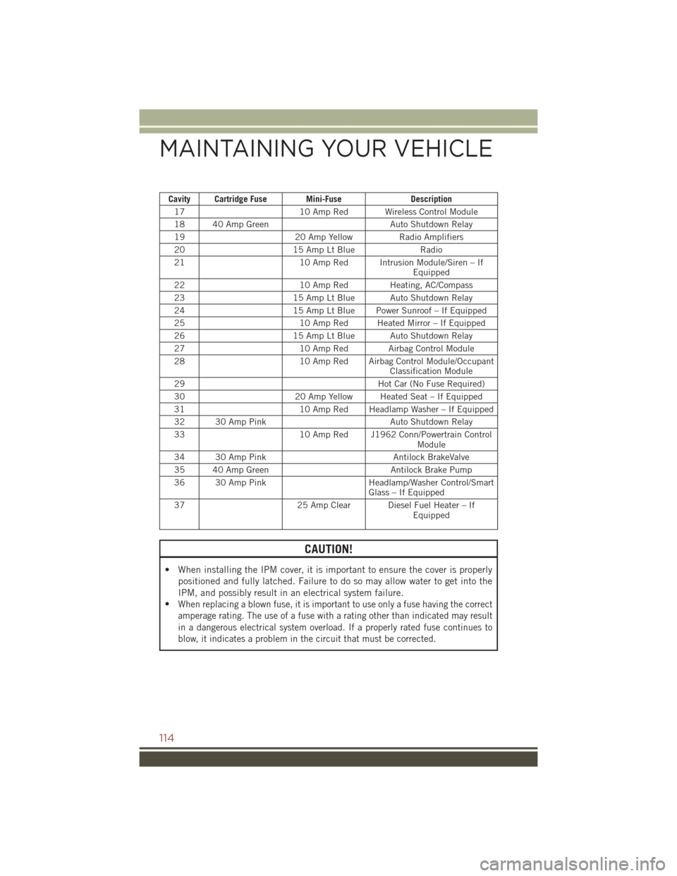
Cavity Cartridge Fuse Mini-FuseDescription
1710 Amp Red Wireless Control Module
18 40 Amp GreenAuto Shutdown Relay
1920 Amp YellowRadio Amplifiers
2015 Amp Lt BlueRadio
2110 Amp Red Intrusion Module/Siren – IfEquipped
2210 Amp Red Heating, AC/Compass
2315 Amp Lt Blue Auto Shutdown Relay
2415 Amp Lt Blue Power Sunroof – If Equipped
2510 Amp Red Heated Mirror – If Equipped
2615 Amp Lt Blue Auto Shutdown Relay
2710 Amp Red Airbag Control Module
2810 Amp Red Airbag Control Module/OccupantClassification Module
29Hot Car (No Fuse Required)
3020 Amp Yellow Heated Seat – If Equipped
3110 Amp Red Headlamp Washer – If Equipped
32 30 Amp PinkAuto Shutdown Relay
3310 Amp Red J1962 Conn/Powertrain ControlModule
34 30 Amp PinkAntilock BrakeValve
35 40 Amp GreenAntilock Brake Pump
36 30 Amp PinkHeadlamp/Washer Control/SmartGlass – If Equipped
3725 Amp Clear Diesel Fuel Heater – IfEquipped
CAUTION!
• When installing the IPM cover, it is important to ensure the cover is properly
positioned and fully latched. Failure to do so may allow water to get into the
IPM, and possibly result in an electrical system failure.
•When replacing a blown fuse, it is important to use only a fuse having the correct
amperage rating. The use of a fuse with a rating other than indicated may result
in a dangerous electrical system overload. If a properly rated fuse continues to
blow, it indicates a problem in the circuit that must be corrected.
MAINTAINING YOUR VEHICLE
114