light JEEP COMPASS 2023 Owners Manual
[x] Cancel search | Manufacturer: JEEP, Model Year: 2023, Model line: COMPASS, Model: JEEP COMPASS 2023Pages: 344, PDF Size: 18.8 MB
Page 5 of 344
3
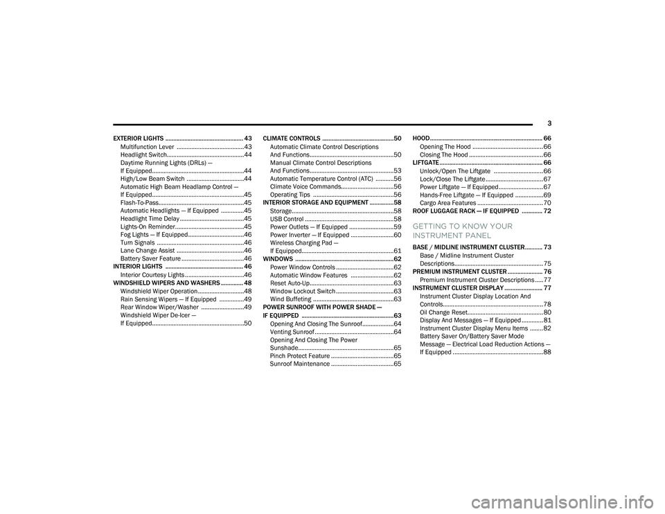
EXTERIOR LIGHTS ................................................. 43 Multifunction Lever .........................................43
Headlight Switch...............................................44
Daytime Running Lights (DRLs) —
If Equipped........................................................44
High/Low Beam Switch ...................................44
Automatic High Beam Headlamp Control —
If Equipped........................................................45
Flash-To-Pass....................................................45
Automatic Headlights — If Equipped ..............45
Headlight Time Delay .......................................45
Lights-On Reminder..........................................45
Fog Lights — If Equipped ..................................46
Turn Signals .....................................................46
Lane Change Assist .........................................46
Battery Saver Feature ......................................46
INTERIOR LIGHTS ................................................. 46
Interior Courtesy Lights ....................................46
WINDSHIELD WIPERS AND WASHERS .............. 48
Windshield Wiper Operation ............................48
Rain Sensing Wipers — If Equipped ...............49
Rear Window Wiper/Washer ..........................49
Windshield Wiper De-Icer —
If Equipped........................................................50 CLIMATE CONTROLS .............................................50
Automatic Climate Control Descriptions
And Functions ...................................................50
Manual Climate Control Descriptions
And Functions ...................................................53
Automatic Temperature Control (ATC) ...........56
Climate Voice Commands................................56
Operating Tips .................................................56
INTERIOR STORAGE AND EQUIPMENT ............... 58
Storage..............................................................58
USB Control ......................................................58
Power Outlets — If Equipped ...........................59
Power Inverter — If Equipped ..........................60
Wireless Charging Pad —
If Equipped........................................................61
WINDOWS ..............................................................62
Power Window Controls ...................................62
Automatic Window Features ..........................62
Reset Auto-Up...................................................63
Window Lockout Switch ...................................63
Wind Buffeting .................................................63
POWER SUNROOF WITH POWER SHADE —
IF EQUIPPED .......................................................... 63
Opening And Closing The Sunroof...................64
Venting Sunroof................................................64
Opening And Closing The Power
Sunshade..........................................................65
Pinch Protect Feature ......................................65
Sunroof Maintenance ......................................65 HOOD....................................................................... 66
Opening The Hood ........................................... 66
Closing The Hood ............................................. 66
LIFTGATE ................................................................. 66
Unlock/Open The Liftgate .............................. 66
Lock/Close The Liftgate................................... 67
Power Liftgate — If Equipped........................... 67
Hands-Free Liftgate — If Equipped ................. 69
Cargo Area Features ........................................ 70
ROOF LUGGAGE RACK — IF EQUIPPED ............. 72
GETTING TO KNOW YOUR
INSTRUMENT PANEL
BASE / MIDLINE INSTRUMENT CLUSTER........... 73
Base / Midline Instrument Cluster
Descriptions...................................................... 75
PREMIUM INSTRUMENT CLUSTER ...................... 76
Premium Instrument Cluster Descriptions ..... 77
INSTRUMENT CLUSTER DISPLAY ........................ 77
Instrument Cluster Display Location And
Controls............................................................. 78
Oil Change Reset.............................................. 80
Display And Messages — If Equipped ............. 81
Instrument Cluster Display Menu Items ........ 82
Battery Saver On/Battery Saver Mode
Message — Electrical Load Reduction Actions —
If Equipped .......................................................88
22_MP_OM_EN_USC_t.book Page 3
Page 6 of 344
4
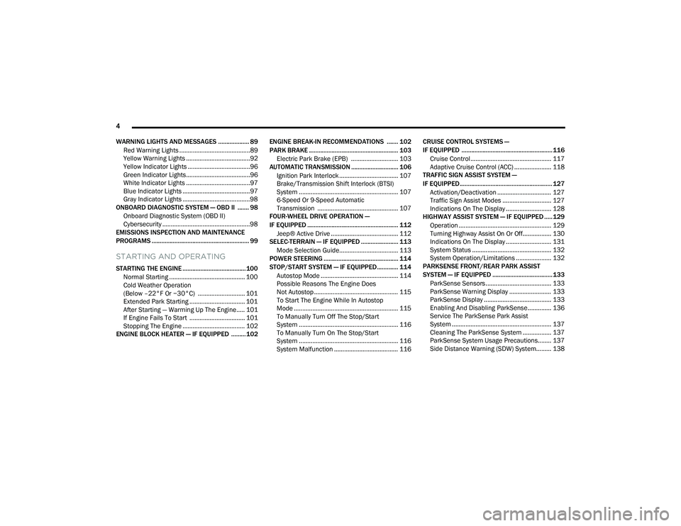
WARNING LIGHTS AND MESSAGES ................... 89 Red Warning Lights ..........................................89
Yellow Warning Lights ......................................92
Yellow Indicator Lights .....................................96
Green Indicator Lights......................................96
White Indicator Lights ......................................97
Blue Indicator Lights ........................................97
Gray Indicator Lights ........................................98
ONBOARD DIAGNOSTIC SYSTEM — OBD II ....... 98
Onboard Diagnostic System (OBD II)
Cybersecurity ....................................................98
EMISSIONS INSPECTION AND MAINTENANCE
PROGRAMS ............................................................ 99
STARTING AND OPERATING
STARTING THE ENGINE ....................................... 100
Normal Starting ............................................. 100
Cold Weather Operation
(Below –22°F Or −30°C) ............................ 101
Extended Park Starting ................................. 101After Starting — Warming Up The Engine..... 101
If Engine Fails To Start ................................. 101Stopping The Engine ..................................... 102
ENGINE BLOCK HEATER — IF EQUIPPED ......... 102 ENGINE BREAK-IN RECOMMENDATIONS ....... 102
PARK BRAKE ....................................................... 103
Electric Park Brake (EPB) ............................ 103
AUTOMATIC TRANSMISSION ............................. 106
Ignition Park Interlock ................................... 107Brake/Transmission Shift Interlock (BTSI)
System ........................................................... 107
6-Speed Or 9-Speed Automatic
Transmission ................................................ 107
FOUR-WHEEL DRIVE OPERATION —
IF EQUIPPED ........................................................ 112
Jeep® Active Drive ........................................ 112
SELEC-TERRAIN — IF EQUIPPED ....................... 113
Mode Selection Guide................................... 113
POWER STEERING .............................................. 114
STOP/START SYSTEM — IF EQUIPPED ............. 114
Autostop Mode .............................................. 114
Possible Reasons The Engine Does
Not Autostop .................................................. 115
To Start The Engine While In Autostop
Mode .............................................................. 115
To Manually Turn Off The Stop/Start
System ........................................................... 116
To Manually Turn On The Stop/Start
System ........................................................... 116
System Malfunction ...................................... 116 CRUISE CONTROL SYSTEMS —
IF EQUIPPED ........................................................ 116
Cruise Control................................................ 117
Adaptive Cruise Control (ACC) ...................... 118
TRAFFIC SIGN ASSIST SYSTEM —
IF EQUIPPED ......................................................... 127
Activation/Deactivation ................................ 127Traffic Sign Assist Modes ............................. 127Indications On The Display ........................... 128
HIGHWAY ASSIST SYSTEM — IF EQUIPPED ..... 129
Operation ....................................................... 129Turning Highway Assist On Or Off................. 130
Indications On The Display ........................... 131
System Status ............................................... 132System Operation/Limitations ..................... 132
PARKSENSE FRONT/REAR PARK ASSIST
SYSTEM — IF EQUIPPED ..................................... 133
ParkSense Sensors ....................................... 133
ParkSense Warning Display ......................... 133
ParkSense Display ........................................ 133
Enabling And Disabling ParkSense.............. 136
Service The ParkSense Park Assist
System ........................................................... 137
Cleaning The ParkSense System ................. 137
ParkSense System Usage Precautions........ 137Side Distance Warning (SDW) System......... 138
22_MP_OM_EN_USC_t.book Page 4
Page 12 of 344
10
VEHICLE MODIFICATIONS/ALTERATIONS
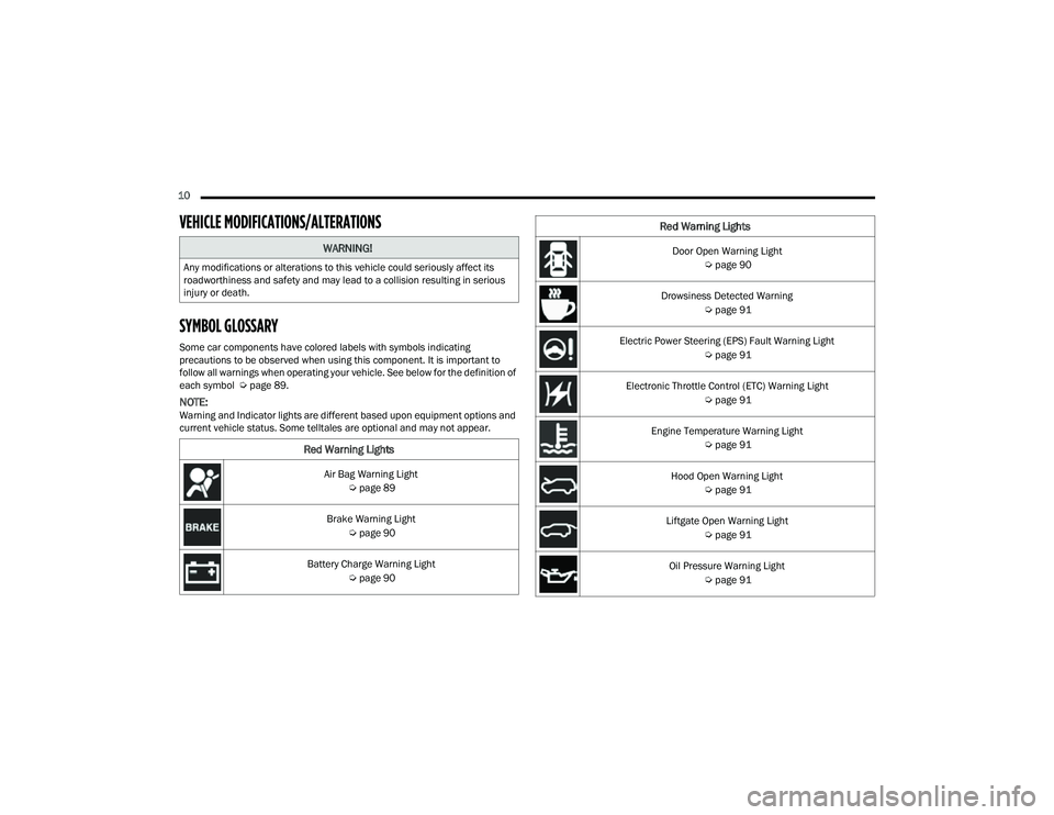
SYMBOL GLOSSARY
Some car components have colored labels with symbols indicating
precautions to be observed when using this component. It is important to
follow all warnings when operating your vehicle. See below for the definition of
each symbol Úpage 89.
NOTE:Warning and Indicator lights are different based upon equipment options and
current vehicle status. Some telltales are optional and may not appear.
WARNING!
Any modifications or alterations to this vehicle could seriously affect its
roadworthiness and safety and may lead to a collision resulting in serious
injury or death.
Red Warning Lights
Air Bag Warning Light
Úpage 89
Brake Warning Light Úpage 90
Battery Charge Warning Light Úpage 90
Door Open Warning Light
Úpage 90
Drowsiness Detected Warning Úpage 91
Electric Power Steering (EPS) Fault Warning Light Úpage 91
Electronic Throttle Control (ETC) Warning Light Úpage 91
Engine Temperature Warning Light Úpage 91
Hood Open Warning Light Úpage 91
Liftgate Open Warning Light Úpage 91
Oil Pressure Warning Light Úpage 91
Red Warning Lights
22_MP_OM_EN_USC_t.book Page 10
Page 13 of 344
11
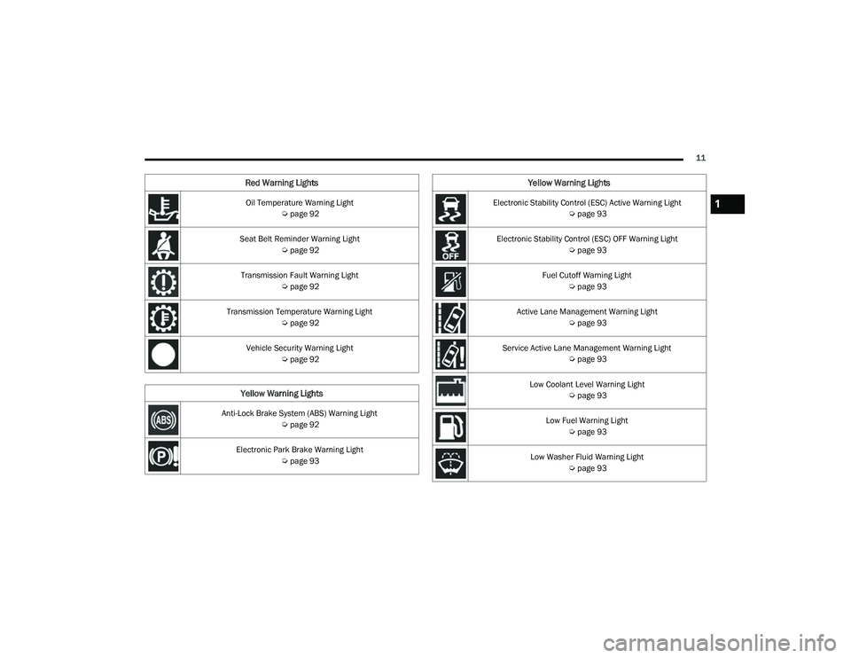
Oil Temperature Warning Light Úpage 92
Seat Belt Reminder Warning Light Úpage 92
Transmission Fault Warning Light Úpage 92
Transmission Temperature Warning Light Úpage 92
Vehicle Security Warning Light Úpage 92
Yellow Warning Lights
Anti-Lock Brake System (ABS) Warning Light
Úpage 92
Electronic Park Brake Warning Light Úpage 93
Red Warning Lights
Electronic Stability Control (ESC) Active Warning Light
Úpage 93
Electronic Stability Control (ESC) OFF Warning Light Úpage 93
Fuel Cutoff Warning Light Úpage 93
Active Lane Management Warning Light Úpage 93
Service Active Lane Management Warning Light Úpage 93
Low Coolant Level Warning Light Úpage 93
Low Fuel Warning Light Úpage 93
Low Washer Fluid Warning Light Úpage 93
Yellow Warning Lights
1
22_MP_OM_EN_USC_t.book Page 11
Page 14 of 344
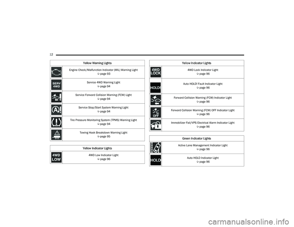
12 Engine Check/Malfunction Indicator (MIL) Warning Light Úpage 93
Service 4WD Warning Light Úpage 94
Service Forward Collision Warning (FCW) Light Úpage 94
Service Stop/Start System Warning Light Úpage 94
Tire Pressure Monitoring System (TPMS) Warning Light Úpage 94
Towing Hook Breakdown Warning Light Úpage 95
Yellow Indicator Lights
4WD Low Indicator Light
Úpage 96
Yellow Warning Lights
4WD Lock Indicator Light
Úpage 96
Auto HOLD! Fault Indicator Light Úpage 96
Forward Collision Warning (FCW) Indicator Light Úpage 96
Forward Collision Warning (FCW) OFF Indicator Light Úpage 96
Immobilizer Fail/VPS Electrical Alarm Indicator Light Úpage 96
Green Indicator Lights
Active Lane Management Indicator Light
Úpage 96
Auto HOLD Indicator Light Úpage 96
Yellow Indicator Lights
22_MP_OM_EN_USC_t.book Page 12
Page 15 of 344
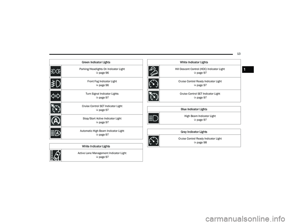
13
Parking/Headlights On Indicator Light Úpage 96
Front Fog Indicator Light Úpage 96
Turn Signal Indicator Lights Úpage 97
Cruise Control SET Indicator Light Úpage 97
Stop/Start Active Indicator Light Úpage 97
Automatic High Beam Indicator Light Úpage 97
White Indicator Lights
Active Lane Management Indicator Light
Úpage 97
Green Indicator Lights
Hill Descent Control (HDC) Indicator Light
Úpage 97
Cruise Control Ready Indicator Light Úpage 97
Cruise Control SET Indicator Light Úpage 97
Blue Indicator Lights
High Beam Indicator Light
Úpage 97
Gray Indicator Lights
Cruise Control Ready Indicator Light
Úpage 98
White Indicator Lights
1
22_MP_OM_EN_USC_t.book Page 13
Page 17 of 344
GETTING TO KNOW YOUR VEHICLE15
NOTE:In case the ignition switch does not change with
the push of a button, the key fob may have a low or
fully depleted battery. A low key fob battery can be
verified by referring to the instrument cluster,
which will display directions to follow Úpage 328.
To Unlock/Lock The Doors And Liftgate
Push and release the unlock button on the key fob
once to unlock the driver’s door. If selected within
Uconnect Settings, pushing the unlock button
twice within five seconds will unlock all the doors
and the liftgate. To lock all the doors and the
liftgate, push the lock button once Ú page 165.
When the doors are unlocked, the turn signals will
flash and the illuminated entry system will be
activated. When the doors are locked, the turn
signals will flash and the horn will chirp.
Key Left Vehicle Feature
If a valid key fob is no longer detected inside the
vehicle while the vehicle’s ignition system is in the
ON/RUN or START position, the message “Key Left
Vehicle” will be shown in the instrument cluster
display along with an interior chime. An exterior
audible and visual alert will also be activated to
warn the driver. The vehicle’s horn will rapidly chirp three times
along with a single flash of the vehicle’s exterior
lights.
NOTE:
The doors have to be open and then closed in
order for the vehicle to check for the presence of
a key fob; the Key Left Vehicle feature will not
activate until all of the doors are closed.
These alerts will not be activated in situations
where the vehicle’s engine is left running with
the key fob inside.
Replacing The Battery In The Key Fob
The replacement battery is one CR2032 battery.
NOTE:
Customers are recommended to use a battery
obtained from Mopar®. Aftermarket coin
battery dimensions may not meet the original
OEM coin battery dimensions.
Perchlorate Material — special handling may
apply. See www.dtsc.ca.gov/hazard
-
ouswaste/perchlorate for further information.
Do not touch the battery terminals that are on
the back housing or the printed circuit board. Key Fob:
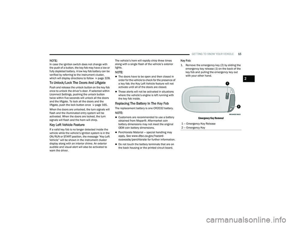
1. Remove the emergency key (2) by sliding the
emergency key release (1) on the back of the
key fob and pulling the emergency key out
with your other hand.
Emergency Key Removal
1 — Emergency Key Release
2 — Emergency Key
2
22_MP_OM_EN_USC_t.book Page 15
Page 19 of 344
GETTING TO KNOW YOUR VEHICLE17
Duplication of key fobs may be performed at an
authorized dealer. This procedure consists of
programming a blank key fob to the vehicle
electronics. A blank key fob is one that has never
been programmed.
NOTE:
When having the Sentry Key Immobilizer system
serviced, bring all vehicle keys with you to an
authorized dealer.
Keys must be ordered to the correct key cut to
match the vehicle locks.
SENTRY KEY
The Sentry Key Immobilizer system prevents
unauthorized vehicle operation by disabling the
engine. The system does not need to be armed or
activated. Operation is automatic, regardless of
whether the vehicle is locked or unlocked.
The system uses a key fob, keyless push button
ignition and a Radio Frequency (RF) receiver to
prevent unauthorized vehicle operation. Therefore,
only key fobs that are programmed to the vehicle
can be used to start and operate the vehicle. The
system cannot reprogram a key fob obtained from
another vehicle. After placing the ignition in the ON/RUN position,
the Vehicle Security Light will turn on for three
seconds for a bulb check. If the light remains on
after the bulb check, it indicates that there is a
problem with the electronics. In addition, if the light
begins to flash after the bulb check, it indicates
that someone attempted to start the engine with
an invalid key fob. In the event that a valid key fob
is used to start the engine but there is an issue
with the vehicle electronics, the engine will start
and shut off after two seconds.
If the Vehicle Security Light turns on during normal
vehicle operation (vehicle running for longer than
10 seconds), it indicates that there is a fault in the
electronics. Should this occur, have the vehicle
serviced as soon as possible by an authorized
dealer.
All of the key fobs provided with your new vehicle
have been programmed to the vehicle electronics
Ú
page 328.
IGNITION SWITCH
KEYLESS ENTER ‘N GO™ IGNITION
This feature allows the driver to operate the
ignition with the push of a button as long as the
key fob is in the passenger compartment.
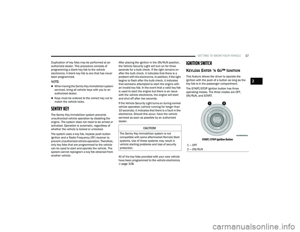
The START/STOP ignition button has three
operating modes. The three modes are OFF,
ON/RUN, and START.
START/STOP Ignition Button
CAUTION!
The Sentry Key Immobilizer system is not
compatible with some aftermarket Remote Start
systems. Use of these systems may result in
vehicle starting problems and loss of security
protection.
1 — OFF
2 — ON/RUN
2
22_MP_OM_EN_USC_t.book Page 17
Page 21 of 344
GETTING TO KNOW YOUR VEHICLE19
(Continued)
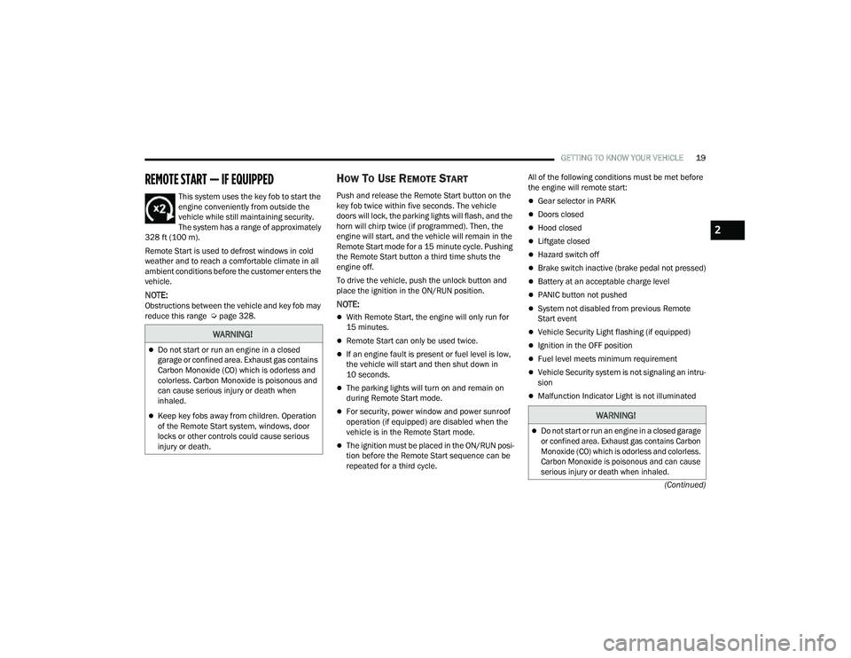
REMOTE START — IF EQUIPPED
This system uses the key fob to start the
engine conveniently from outside the
vehicle while still maintaining security.
The system has a range of approximately
328 ft (100 m).
Remote Start is used to defrost windows in cold
weather and to reach a comfortable climate in all
ambient conditions before the customer enters the
vehicle.
NOTE:Obstructions between the vehicle and key fob may
reduce this range Ú page 328.
HOW TO USE REMOTE START
Push and release the Remote Start button on the
key fob twice within five seconds. The vehicle
doors will lock, the parking lights will flash, and the
horn will chirp twice (if programmed). Then, the
engine will start, and the vehicle will remain in the
Remote Start mode for a 15 minute cycle. Pushing
the Remote Start button a third time shuts the
engine off.
To drive the vehicle, push the unlock button and
place the ignition in the ON/RUN position.
NOTE:
With Remote Start, the engine will only run for
15 minutes.
Remote Start can only be used twice.
If an engine fault is present or fuel level is low,
the vehicle will start and then shut down in
10 seconds.
The parking lights will turn on and remain on
during Remote Start mode.
For security, power window and power sunroof
operation (if equipped) are disabled when the
vehicle is in the Remote Start mode.
The ignition must be placed in the ON/RUN posi -
tion before the Remote Start sequence can be
repeated for a third cycle. All of the following conditions must be met before
the engine will remote start:
Gear selector in PARK
Doors closed
Hood closed
Liftgate closed
Hazard switch off
Brake switch inactive (brake pedal not pressed)
Battery at an acceptable charge level
PANIC button not pushed
System not disabled from previous Remote
Start event
Vehicle Security Light flashing (if equipped)
Ignition in the OFF position
Fuel level meets minimum requirement
Vehicle Security system is not signaling an intru
-
sion
Malfunction Indicator Light is not illuminated
WARNING!
Do not start or run an engine in a closed
garage or confined area. Exhaust gas contains
Carbon Monoxide (CO) which is odorless and
colorless. Carbon Monoxide is poisonous and
can cause serious injury or death when
inhaled.
Keep key fobs away from children. Operation
of the Remote Start system, windows, door
locks or other controls could cause serious
injury or death.WARNING!
Do not start or run an engine in a closed garage
or confined area. Exhaust gas contains Carbon
Monoxide (CO) which is odorless and colorless.
Carbon Monoxide is poisonous and can cause
serious injury or death when inhaled.
2
22_MP_OM_EN_USC_t.book Page 19
Page 23 of 344
GETTING TO KNOW YOUR VEHICLE21
adjusted by the driver while the vehicle is in Remote
Start mode. This includes turning the climate
controls off using the OFF button.
REMOTE START WINDSHIELD WIPER
D
E–ICER ACTIVATION — IF EQUIPPED
When Remote Start is active and the outside
ambient temperature is less than 33°F (0.6°C),
the Windshield Wiper De-Icer will activate. Exiting
Remote Start will resume its previous operation. If
the Windshield Wiper De-Icer was active, the timer
and operation will continue.
REMOTE START ABORT MESSAGE —
I
F EQUIPPED
The following messages will display in the
instrument cluster display if the vehicle fails to
remote start or exits Remote Start prematurely:
Remote Start Aborted — Door Open
Remote Start Aborted — Hood Open
Remote Start Aborted — Fuel Low
Remote Start Aborted — Liftgate Open
Remote Start Disabled — Start Vehicle To Reset
Remote Start Aborted — Too Cold
Remote Start Aborted — Time Expired
Remote Start Disabled — Start Vehicle To Reset
The message will stay active until the ignition is
placed in the ON/RUN position.
VEHICLE SECURITY SYSTEM — IF EQUIPPED
The Vehicle Security system monitors the vehicle
doors, hood, liftgate, and the Keyless Enter ‘n Go™
Ignition for unauthorized operation. While the
Vehicle Security system is armed, interior switches
for door locks and liftgate release are disabled. If
something triggers the system, the Vehicle Security
system will provide the following audible and
visible signals:
The horn will pulse
The turn signals will flash
The Vehicle Security Light in the instrument
cluster will flash
NOTE:
The Vehicle Security system is factory adjusted
to standards from different countries.
The Vehicle Security system is a complementary
security system developed to hinder the occur -
rence of vehicle theft and prevent vandalism. It
does not prevent the theft of your vehicle; the
system is a deterrent.
The Vehicle Security system does not monitor
glass breakage or the movement of objects or
people inside the vehicle. The alarm does not
intervene in the case of vehicle tilt variations
when it is parked.
TO ARM THE SYSTEM
Follow these steps to arm the Vehicle Security
system:
1. Make sure the vehicle’s ignition is placed in the OFF position.
For vehicles equipped with Keyless Entry,
make sure the vehicle’s keyless ignition
system is OFF.
2. Perform one of the following methods to lock the vehicle:
Push the lock button on the interior power
door lock switch with the driver and/or
passenger door open.
Push the lock button on the exterior Passive
Entry door handle with a valid key fob avail -
able in the same exterior zone Ú page 23.
Push the lock button on the key fob.
3. If any doors are open, close them.
When the Vehicle Security system is armed, the
Vehicle Security Light (located in the lower left
portion of the instrument cluster display) will begin
to flash every three seconds until it is disarmed.
2
22_MP_OM_EN_USC_t.book Page 21