light JEEP COMPASS 2023 Owner's Manual
[x] Cancel search | Manufacturer: JEEP, Model Year: 2023, Model line: COMPASS, Model: JEEP COMPASS 2023Pages: 344, PDF Size: 18.8 MB
Page 49 of 344
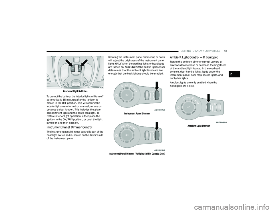
GETTING TO KNOW YOUR VEHICLE47
Overhead Light Switches
To protect the battery, the interior lights will turn off
automatically 15 minutes after the ignition is
placed in the OFF position. This will occur if the
interior lights were turned on manually or are on
because a door is open. This includes the glove
compartment light and the cargo area light. To
restore interior light operation, either place the
ignition in the ON/RUN position, or push the light
switch on and then back off.
Instrument Panel Dimmer Control
The instrument panel dimmer control is part of the
headlight switch and is located on the driver’s side
of the instrument panel. Rotating the instrument panel dimmer up or down
will adjust the brightness of the instrument panel
lights
ONLY when the parking lights or headlights
are turned on, AND ONLY if the built in light sensor
determines that the ambient light levels are low
enough that the backlighting should be enabled.
Instrument Panel Dimmer
Instrument Panel Dimmer (Vehicles Sold In Canada Only)
Ambient Light Control — If Equipped
Rotate the ambient dimmer control upward or
downward to increase or decrease the brightness
of the ambient light located in the overhead
console, door handle lights, lights under the
instrument panel, door map pocket lights, and
cubby bin lights.
Ambient lights are only enabled when the
headlights are active.
Ambient Light Dimmer
2
22_MP_OM_EN_USC_t.book Page 47
Page 50 of 344
48GETTING TO KNOW YOUR VEHICLE
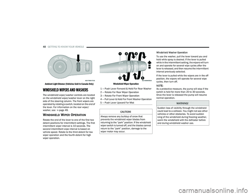
Ambient Light Dimmer (Vehicles Sold In Canada Only)
WINDSHIELD WIPERS AND WASHERS
The windshield wiper/washer controls are located
on the windshield wiper/washer lever on the right
side of the steering column. The front wipers are
operated by rotating a switch, located on the end of
the lever. For information on the rear wiper/
washer, see Ú page 49.
WINDSHIELD WIPER OPERATION
Rotate the end of the lever to one of the first two
detent positions for intermittent settings. The first
intermittent wiper interval is 10 seconds. The
second intermittent wipe interval is based on
vehicle speed. Rotate to the third detent for low
wiper operation and the fourth detent for high
wiper operation.
Windshield Wiper Operation
Windshield Washer Operation
To use the washer, pull the lever toward you and
hold while spray is desired. If the lever is pulled
while in the intermittent setting, the wipers will turn
on and operate for several wipe cycles after the
lever is released, and then resume the intermittent
interval previously selected.
If the lever is pulled while the wipers are in the off
position, the wipers will operate for several wipe
cycles, then turn off.
NOTE:As a protective measure, the pump will stop if the
switch is held for more than 20 to 30 seconds.
Once the lever is released the pump will resume
normal operation.1 — Push Lever Forward & Hold For Rear Washer
2 — Rotate For Rear Wiper Operation
3 — Rotate For Front Wiper Operation
4 — Pull Lever & Hold For Front Washer Operation
5 — Push Lever Upward For Mist
CAUTION!
Always remove any buildup of snow that
prevents the windshield wiper blades from
returning to the “park” position. If the windshield
wiper switch is turned off, and the blades cannot
return to the “park” position, damage to the
wiper motor may occur.
WARNING!
Sudden loss of visibility through the windshield
could lead to a collision. You might not see other
vehicles or other obstacles. To avoid sudden
icing of the windshield during freezing weather,
warm the windshield with the defroster before
and during windshield washer use.
22_MP_OM_EN_USC_t.book Page 48
Page 55 of 344
GETTING TO KNOW YOUR VEHICLE53
Panel Mode
Air comes from the outlets in the
instrument panel. Each of these outlets
can be individually adjusted to direct the
flow of air. The air vanes of the center
outlets and outboard outlets can be moved up and
down or side to side to regulate airflow direction.
There is a shut-off wheel located below the air
vanes to shut off or adjust the amount of airflow
from these outlets.
Bi-Level Mode
Air comes from the instrument panel
outlets and floor outlets. A slight amount
of air is directed through the defrost and
side window demister outlets.
NOTE:Bi-Level mode is designed under comfort condi -
tions to provide cooler air out of the panel outlets
and warmer air from the floor outlets.
Floor Mode
Air comes from the floor outlets. A slight
amount of air is directed through the
defrost, side window demister outlets,
and panel outboard outlets.
Defrost Mode
Air comes from the windshield and side
window demist outlets. When the defrost
button is selected, the blower level may
increase. Use Defrost mode with
maximum temperature settings for best
windshield and side window defrosting and
defogging. When toggling the front defrost mode
button, the Climate Control system will return to
the previous setting.
Mix Mode
Air is directed through the floor, defrost,
and side window demister outlets. This
setting works best in cold or snowy
conditions that require extra heat to the
windshield. This setting is good for maintaining
comfort while reducing moisture on the
windshield. A slight amount of air is also directed
through the panel outboard outlets.
Climate Control OFF Button
Press and release this button on the
touchscreen, or push and release the
button on the faceplate to turn the
Climate Control ON/OFF.
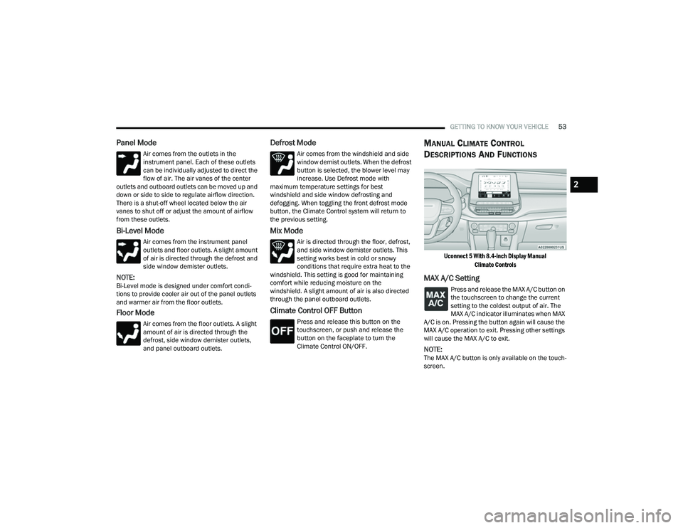
MANUAL CLIMATE CONTROL
D
ESCRIPTIONS AND FUNCTIONS
Uconnect 5 With 8.4-inch Display Manual
Climate Controls
MAX A/C Setting
Press and release the MAX A/C button on
the touchscreen to change the current
setting to the coldest output of air. The
MAX A/C indicator illuminates when MAX
A/C is on. Pressing the button again will cause the
MAX A/C operation to exit. Pressing other settings
will cause the MAX A/C to exit.
NOTE:The MAX A/C button is only available on the touch -
screen.
2
22_MP_OM_EN_USC_t.book Page 53
Page 57 of 344
GETTING TO KNOW YOUR VEHICLE55
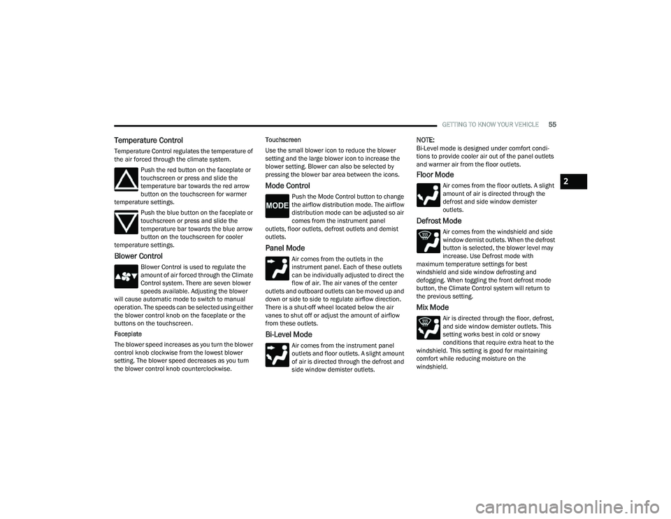
Temperature Control
Temperature Control regulates the temperature of
the air forced through the climate system.
Push the red button on the faceplate or
touchscreen or press and slide the
temperature bar towards the red arrow
button on the touchscreen for warmer
temperature settings.
Push the blue button on the faceplate or
touchscreen or press and slide the
temperature bar towards the blue arrow
button on the touchscreen for cooler
temperature settings.
Blower Control
Blower Control is used to regulate the
amount of air forced through the Climate
Control system. There are seven blower
speeds available. Adjusting the blower
will cause automatic mode to switch to manual
operation. The speeds can be selected using either
the blower control knob on the faceplate or the
buttons on the touchscreen.
Faceplate
The blower speed increases as you turn the blower
control knob clockwise from the lowest blower
setting. The blower speed decreases as you turn
the blower control knob counterclockwise. Touchscreen
Use the small blower icon to reduce the blower
setting and the large blower icon to increase the
blower setting. Blower can also be selected by
pressing the blower bar area between the icons.
Mode Control
Push the Mode Control button to change
the airflow distribution mode. The airflow
distribution mode can be adjusted so air
comes from the instrument panel
outlets, floor outlets, defrost outlets and demist
outlets.
Panel Mode
Air comes from the outlets in the
instrument panel. Each of these outlets
can be individually adjusted to direct the
flow of air. The air vanes of the center
outlets and outboard outlets can be moved up and
down or side to side to regulate airflow direction.
There is a shut-off wheel located below the air
vanes to shut off or adjust the amount of airflow
from these outlets.
Bi-Level Mode
Air comes from the instrument panel
outlets and floor outlets. A slight amount
of air is directed through the defrost and
side window demister outlets.
NOTE:Bi-Level mode is designed under comfort condi -
tions to provide cooler air out of the panel outlets
and warmer air from the floor outlets.
Floor Mode
Air comes from the floor outlets. A slight
amount of air is directed through the
defrost and side window demister
outlets.
Defrost Mode
Air comes from the windshield and side
window demist outlets. When the defrost
button is selected, the blower level may
increase. Use Defrost mode with
maximum temperature settings for best
windshield and side window defrosting and
defogging. When toggling the front defrost mode
button, the Climate Control system will return to
the previous setting.
Mix Mode
Air is directed through the floor, defrost,
and side window demister outlets. This
setting works best in cold or snowy
conditions that require extra heat to the
windshield. This setting is good for maintaining
comfort while reducing moisture on the
windshield.
2
22_MP_OM_EN_USC_t.book Page 55
Page 62 of 344
60GETTING TO KNOW YOUR VEHICLE
(Continued)
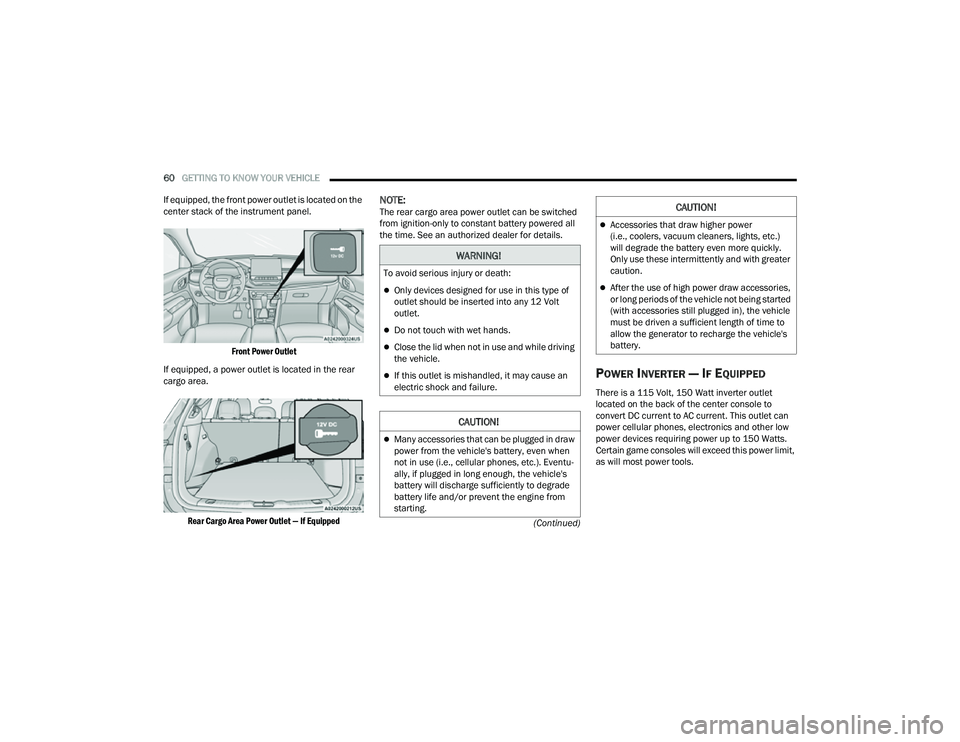
If equipped, the front power outlet is located on the
center stack of the instrument panel.
Front Power Outlet
If equipped, a power outlet is located in the rear
cargo area.
Rear Cargo Area Power Outlet — If Equipped
NOTE:The rear cargo area power outlet can be switched
from ignition-only to constant battery powered all
the time. See an authorized dealer for details.
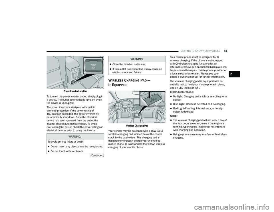
POWER INVERTER — IF EQUIPPED
There is a 115 Volt, 150 Watt inverter outlet
located on the back of the center console to
convert DC current to AC current. This outlet can
power cellular phones, electronics and other low
power devices requiring power up to 150 Watts.
Certain game consoles will exceed this power limit,
as will most power tools.
WARNING!
To avoid serious injury or death:
Only devices designed for use in this type of
outlet should be inserted into any 12 Volt
outlet.
Do not touch with wet hands.
Close the lid when not in use and while driving
the vehicle.
If this outlet is mishandled, it may cause an
electric shock and failure.
CAUTION!
Many accessories that can be plugged in draw
power from the vehicle's battery, even when
not in use (i.e., cellular phones, etc.). Eventu -
ally, if plugged in long enough, the vehicle's
battery will discharge sufficiently to degrade
battery life and/or prevent the engine from
starting.
Accessories that draw higher power
(i.e., coolers, vacuum cleaners, lights, etc.)
will degrade the battery even more quickly.
Only use these intermittently and with greater
caution.
After the use of high power draw accessories,
or long periods of the vehicle not being started
(with accessories still plugged in), the vehicle
must be driven a sufficient length of time to
allow the generator to recharge the vehicle's
battery.
CAUTION!
22_MP_OM_EN_USC_t.book Page 60
Page 63 of 344
GETTING TO KNOW YOUR VEHICLE61
(Continued)
Power Inverter Location
To turn on the power inverter outlet, simply plug in
a device. The outlet automatically turns off when
the device is unplugged.
The power inverter is designed with built-in
overload protection. If the power rating of
150 Watts is exceeded, the power inverter will
automatically shut down. Once the electrical
device has been removed from the outlet the
inverter should automatically reset. To avoid
overloading the circuit, check the power ratings on
electrical devices prior to using the inverter.
WIRELESS CHARGING PAD —
I
F EQUIPPED
Wireless Charging Pad
Your vehicle may be equipped with a 15W 3A Qi
wireless charging pad located below the center
stack by the cupholders. This charging pad is
designed to wirelessly charge your Qi enabled
mobile phone. Qi is a standard that allows wireless
charging of your mobile phone. Your mobile phone must be designed for Qi
wireless charging. If the phone is not equipped
with Qi wireless charging functionality, an
aftermarket sleeve or a specialized back plate can
be purchased from your mobile phone provider or
a local electronics retailer. Please see your
phone’s owner’s manual for further information.
The wireless charging pad is equipped with an
anti-slip mat to hold your mobile phone in place,
and an LED indicator light.
LED Indicator Status:
No Light: Charging pad is idle or searching for a
device.
Blue Light: Device is detected and is charging.
Red Light/Flashing: Internal error, or foreign
object is detected.
NOTE:
The wireless charging pad will not work if any of
the four doors are open, even if the engine is
running. Opening the liftgate will not interfere
with charging pad operation.
Using a phone case may interfere with wireless
charging.WARNING!
To avoid serious injury or death:
Do not insert any objects into the receptacles.
Do not touch with wet hands.
Close the lid when not in use.
If this outlet is mishandled, it may cause an
electric shock and failure.
WARNING!
2
22_MP_OM_EN_USC_t.book Page 61
Page 64 of 344
62GETTING TO KNOW YOUR VEHICLE
WINDOWS
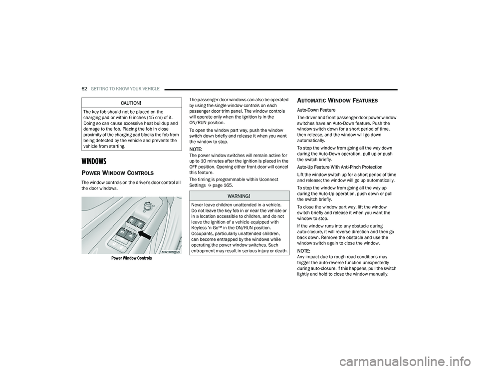
POWER WINDOW CONTROLS
The window controls on the driver's door control all
the door windows.
Power Window Controls
The passenger door windows can also be operated
by using the single window controls on each
passenger door trim panel. The window controls
will operate only when the ignition is in the
ON/RUN position.
To open the window part way, push the window
switch down briefly and release it when you want
the window to stop.
NOTE:The power window switches will remain active for
up to 10 minutes after the ignition is placed in the
OFF position. Opening either front door will cancel
this feature.
The timing is programmable within Uconnect
Settings Ú
page 165.
AUTOMATIC WINDOW FEATURES
Auto-Down Feature
The driver and front passenger door power window
switches have an Auto-Down feature. Push the
window switch down for a short period of time,
then release, and the window will go down
automatically.
To stop the window from going all the way down
during the Auto-Down operation, pull up or push
the switch briefly.
Auto-Up Feature With Anti-Pinch Protection
Lift the window switch up for a short period of time
and release; the window will go up automatically.
To stop the window from going all the way up
during the Auto-Up operation, push down or pull
the switch briefly.
To close the window part way, lift the window
switch briefly and release it when you want the
window to stop.
If the window runs into any obstacle during
auto-closure, it will reverse direction and then go
back down. Remove the obstacle and use the
window switch again to close the window.
NOTE:Any impact due to rough road conditions may
trigger the auto-reverse function unexpectedly
during auto-closure. If this happens, pull the switch
lightly and hold to close the window manually.
CAUTION!
The key fob should not be placed on the
charging pad or within 6 inches (15 cm) of it.
Doing so can cause excessive heat buildup and
damage to the fob. Placing the fob in close
proximity of the charging pad blocks the fob from
being detected by the vehicle and prevents the
vehicle from starting.
WARNING!
Never leave children unattended in a vehicle.
Do not leave the key fob in or near the vehicle or
in a location accessible to children, and do not
leave the ignition of a vehicle equipped with
Keyless ‘n Go™ in the ON/RUN position.
Occupants, particularly unattended children,
can become entrapped by the windows while
operating the power window switches. Such
entrapment may result in serious injury or death.
22_MP_OM_EN_USC_t.book Page 62
Page 65 of 344
GETTING TO KNOW YOUR VEHICLE63
RESET AUTO-UP
Should the Auto-Up feature stop working, the
window probably needs to be reset. To reset
Auto-Up:
1. Pull the window switch up to close the window
completely and continue to hold the switch up
for an additional two seconds after the
window is closed.
2. Push the window switch down firmly to open the window completely and continue to hold
the switch down for an additional two seconds
after the window is fully open.
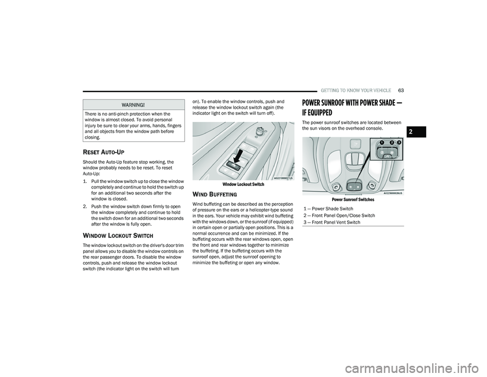
WINDOW LOCKOUT SWITCH
The window lockout switch on the driver's door trim
panel allows you to disable the window controls on
the rear passenger doors. To disable the window
controls, push and release the window lockout
switch (the indicator light on the switch will turn on). To enable the window controls, push and
release the window lockout switch again (the
indicator light on the switch will turn off).
Window Lockout Switch
WIND BUFFETING
Wind buffeting can be described as the perception
of pressure on the ears or a helicopter-type sound
in the ears. Your vehicle may exhibit wind buffeting
with the windows down, or the sunroof (if equipped)
in certain open or partially open positions. This is a
normal occurrence and can be minimized. If the
buffeting occurs with the rear windows open, open
the front and rear windows together to minimize
the buffeting. If the buffeting occurs with the
sunroof open, adjust the sunroof opening to
minimize the buffeting or open any window.
POWER SUNROOF WITH POWER SHADE —
IF EQUIPPED
The power sunroof switches are located between
the sun visors on the overhead console.
Power Sunroof Switches
WARNING!
There is no anti-pinch protection when the
window is almost closed. To avoid personal
injury be sure to clear your arms, hands, fingers
and all objects from the window path before
closing.
1 — Power Shade Switch
2 — Front Panel Open/Close Switch
3 — Front Panel Vent Switch
2
22_MP_OM_EN_USC_t.book Page 63
Page 70 of 344
68GETTING TO KNOW YOUR VEHICLE
The key fob and the overhead console switch will
open the liftgate when the liftgate is locked. The
outside handle requires the liftgate to be unlocked.
If the vehicle is equipped with Passive Entry, and a
valid Passive Entry key fob is within 5 ft (1.5 m) of the liftgate, pulling the outside handle will unlock
and open the liftgate.
NOTE:
Before closing the liftgate, make sure to be in
possession of the key because the liftgate may
be locked.
Use the interior door lock/unlock button on the
door panel or the key fob to lock and unlock the
liftgate. The manual door locks on the doors and
the exterior door lock cylinder will not lock and
unlock the liftgate.
The liftgate will either unlock along with the
vehicle doors, or it will need to be unlocked by
pushing the electronic liftgate release,
depending on the selected setting in the
Uconnect system Ú page 165.
The power liftgate buttons will not operate if the
vehicle is in gear or the vehicle speed is above
0 mph (0 km/h).
The power liftgate will not operate in tempera -
tures below −22°F (−30°C) or temperatures
above 150°F (65°C). Be sure to remove any
buildup of snow or ice from the liftgate before
pushing any of the power liftgate switches.
If anything obstructs the power liftgate while it is
closing or opening, the liftgate will automatically
reverse to the closed or open position. After
multiple obstructions in the same cycle, the lift -
gate will automatically stop and must be opened
or closed manually.
There are pinch sensors attached to the side of
the liftgate. Light pressure anywhere along
these strips will cause the liftgate to return to
the open position.
The power liftgate must be in the full open posi -
tion in order for the rear liftgate close button, on
the left rear trim near the liftgate opening, to
operate. If the liftgate is not fully open, push the
liftgate button on the key fob to fully open the
liftgate and then push it again to close.
If the electronic liftgate release handle is
pushed a second time while the power liftgate is
opening, the liftgate motor will disengage to
allow manual operation.
If your liftgate is power closing and you put the
vehicle in gear, the liftgate will continue to
power close. However, vehicle movement may
result in the detection of an obstruction.
Allow the power system to open the liftgate.
Manually pushing or pulling the liftgate may acti -
vate the liftgate obstacle detection feature and
stop the power operation or reverse its direc -
tion. Lock The Vehicle
With a valid Passive Entry key fob within 5 ft
(1.5 m) of the liftgate, pushing the Passive Entry
lock button located to the right of the electronic
liftgate release handle will lock the vehicle.
WARNING!
Driving with the liftgate open can allow
poisonous exhaust gases into your vehicle.
You and your passengers could be injured by
these fumes. Keep the liftgate closed when
you are operating the vehicle.
If you are required to drive with the liftgate
open, make sure that all windows are closed,
and the climate control blower switch is set at
high speed. Do not use the recirculation
mode.
During power operation, personal injury or
cargo damage may occur. Ensure the liftgate
travel path is clear. Make sure the liftgate is
closed and latched before driving away.
Personal injury or cargo damage may occur if
caught in the path of the liftgate. Make sure
the liftgate path is clear before activating the
liftgate.
22_MP_OM_EN_USC_t.book Page 68
Page 71 of 344
GETTING TO KNOW YOUR VEHICLE69
(Continued)
HANDS-FREE LIFTGATE — IF EQUIPPED
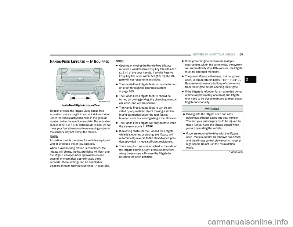
Hands-Free Liftgate Activation Zone
To open or close the liftgate using hands-free
activation, use a straight in and out kicking motion
under the vehicle activation zone in the general
location below the rear license plate. The activation
zone is about 1.8 ft (0.5 m) from side to side. Do not move your foot sideways or in a sweeping motion or
the sensors may not detect the motion.
NOTE:Activation zone is the same for vehicles equipped
with or without a trailer tow package.
When a valid kicking motion is completed, the
liftgate will chime, the hazard lights will flash and
the liftgate will open after approximately one
second, or close after approximately three
seconds. These settings can be enabled or
disabled through Uconnect Settings Ú page 165.
NOTE:
Opening or closing the Hands-Free Liftgate
requires a valid Passive Entry key fob within 5 ft
(1.5 m) of the door handle. If a valid Passive
Entry key fob is not within 5 ft (1.5 m), the lift -
gate will not respond to any kicks.
The Hands-Free Liftgate feature may be turned
on or off through the Uconnect system
Ú page 165.
The Hands-Free Liftgate feature should be
turned off during jacking, tire changing, manual
car wash, and vehicle service.
The Hands-Free Liftgate feature can be acti -
vated by any metallic object making a similar
in-and-out motion under the rear fascia/
bumper, such as cleaning using a metal broom.
The Hands-Free Liftgate will only operate when
the transmission is in PARK.
If anything obstructs the Hands-Free Liftgate
while it is opening or closing, the liftgate will
automatically reverse to the closed/open posi -
tion, provided it meets sufficient resistance.
There are pinch sensors attached to the side of
the liftgate opening. Light pressure anywhere
along these strips will cause the liftgate to
return to the open position.
If the power liftgate encounters multiple
obstructions within the same cycle, the system
will automatically stop. If this occurs, the liftgate
must be operated manually.
The power liftgate will release, but not power
open, in temperatures below −12°F (−24°C).
Be sure to remove any buildup of snow or ice
from the liftgate before opening the liftgate.
If the liftgate is left open for an extended period
of time (approximately one hour), the liftgate
may need to be closed manually to reset power
liftgate functionality.
WARNING!
Driving with the liftgate open can allow
poisonous exhaust gases into your vehicle.
You and your passengers could be injured by
these fumes. Keep the liftgate closed when
you are operating the vehicle.
If you are required to drive with the liftgate
open, make sure that all windows are closed,
and the climate control blower switch is set at
high speed. Do not use the recirculation
mode.
2
22_MP_OM_EN_USC_t.book Page 69