run flat JEEP COMPASS 2023 Owners Manual
[x] Cancel search | Manufacturer: JEEP, Model Year: 2023, Model line: COMPASS, Model: JEEP COMPASS 2023Pages: 344, PDF Size: 18.8 MB
Page 96 of 344
94GETTING TO KNOW YOUR INSTRUMENT PANEL
Certain conditions, such as a loose or missing gas
cap, poor quality fuel, etc., may illuminate the light
after engine start. The vehicle should be serviced if
the light stays on through several typical driving
styles. In most situations, the vehicle will drive
normally and will not require towing.
When the engine is running, the MIL may flash to
alert serious conditions that could lead to
immediate loss of power or severe catalytic
converter damage. The vehicle should be serviced
by an authorized dealer as soon as possible if this
occurs.
Service 4WD Warning Light — If Equipped
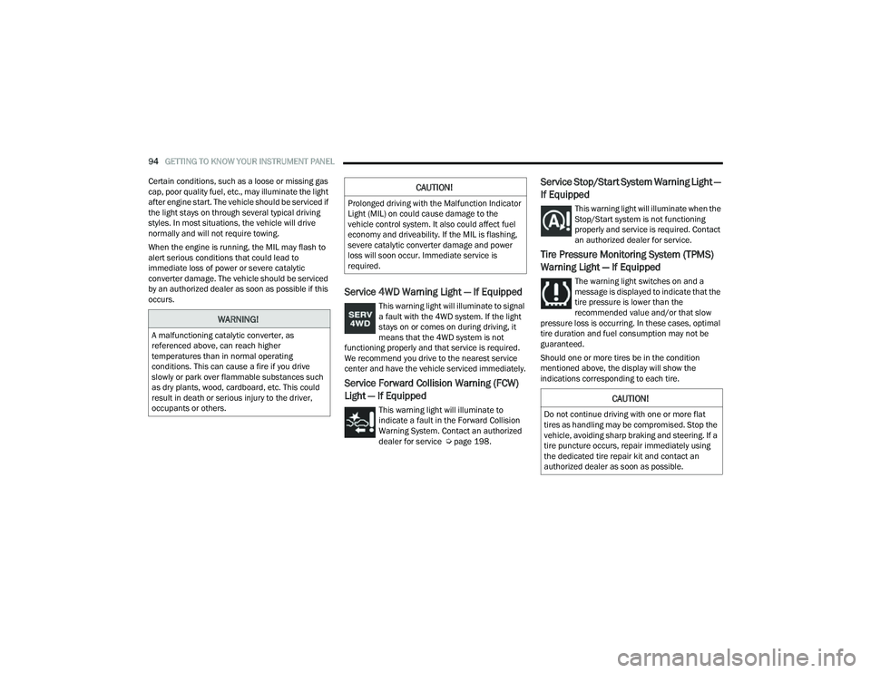
This warning light will illuminate to signal
a fault with the 4WD system. If the light
stays on or comes on during driving, it
means that the 4WD system is not
functioning properly and that service is required.
We recommend you drive to the nearest service
center and have the vehicle serviced immediately.
Service Forward Collision Warning (FCW)
Light — If Equipped
This warning light will illuminate to
indicate a fault in the Forward Collision
Warning System. Contact an authorized
dealer for service Ú page 198.
Service Stop/Start System Warning Light —
If Equipped
This warning light will illuminate when the
Stop/Start system is not functioning
properly and service is required. Contact
an authorized dealer for service.
Tire Pressure Monitoring System (TPMS)
Warning Light — If Equipped
The warning light switches on and a
message is displayed to indicate that the
tire pressure is lower than the
recommended value and/or that slow
pressure loss is occurring. In these cases, optimal
tire duration and fuel consumption may not be
guaranteed.
Should one or more tires be in the condition
mentioned above, the display will show the
indications corresponding to each tire.
WARNING!
A malfunctioning catalytic converter, as
referenced above, can reach higher
temperatures than in normal operating
conditions. This can cause a fire if you drive
slowly or park over flammable substances such
as dry plants, wood, cardboard, etc. This could
result in death or serious injury to the driver,
occupants or others.
CAUTION!
Prolonged driving with the Malfunction Indicator
Light (MIL) on could cause damage to the
vehicle control system. It also could affect fuel
economy and driveability. If the MIL is flashing,
severe catalytic converter damage and power
loss will soon occur. Immediate service is
required.
CAUTION!
Do not continue driving with one or more flat
tires as handling may be compromised. Stop the
vehicle, avoiding sharp braking and steering. If a
tire puncture occurs, repair immediately using
the dedicated tire repair kit and contact an
authorized dealer as soon as possible.
22_MP_OM_EN_USC_t.book Page 94
Page 155 of 344
STARTING AND OPERATING153
4. Keep the nozzle in the filler for five seconds after nozzle clicks to allow fuel to drain from
the nozzle.
5. Remove the fuel nozzle and close the fuel door.
VEHICLE LOADING
CERTIFICATION LABEL
As required by National Highway Traffic Safety
Administration regulations, your vehicle has a
certification label affixed to the driver's side door or
pillar. This label contains the month and year of
manufacture, Gross Vehicle Weight Rating
(GVWR), front and rear Gross Axle Weight Rating
(GAWR), and Vehicle Identification Number (VIN).
A Month-Day-Hour (MDH) number is included on
this label and indicates the Month, Day and Hour of
manufacture. The bar code that appears on the
bottom of the label is your VIN.
Gross Vehicle Weight Rating (GVWR)
The GVWR is the total permissible weight of your
vehicle including driver, passengers, vehicle,
options and cargo. The label also specifies
maximum capacities of front and rear Gross Axle
Weight Rating (GAWR). Total load must be limited so
GVWR and front and rear GAWR are not exceeded.
Payload
The payload of a vehicle is defined as the allowable
load weight a truck can carry, including the weight
of the driver, all passengers, options and cargo.
Gross Axle Weight Rating (GAWR)
The GAWR is the maximum permissible load on the
front and rear axles. The load must be distributed
in the cargo area so that the GAWR of each axle is
not exceeded.
Each axle GAWR is determined by the components
in the system with the lowest load carrying capacity
(axle, springs, tires or wheels). Heavier axles or suspension components sometimes specified by
purchasers for increased durability does not
necessarily increase the vehicle's GVWR.
Tire Size
The tire size on the Vehicle Certification Label
represents the actual tire size on your vehicle.
Replacement tires must be equal to the load
capacity of this tire size.
Rim Size
This is the rim size that is appropriate for the tire
size listed.
Inflation Pressure
This is the cold tire inflation pressure for your
vehicle for all loading conditions up to full GAWR.
Curb Weight
The curb weight of a vehicle is defined as the total
weight of the vehicle with all fluids, including
vehicle fuel, at full capacity conditions, and with no
occupants or cargo loaded into the vehicle. The
front and rear curb weight values are determined
by weighing your vehicle on a commercial scale
before any occupants or cargo are added.
Loading
The actual total weight and the weight of the front
and rear of your vehicle at the ground can best be
determined by weighing it when it is loaded and
ready for operation.
WARNING!
Never have any smoking materials lit in or
near the vehicle when the fuel door is open or
the tank is being filled.
Never add fuel when the engine is running.
This is in violation of most state and federal
fire regulations and may cause the Malfunc
-
tion Indicator Light to turn on.
A fire may result if fuel is pumped into a
portable container that is inside of a vehicle.
You could be burned. Always place fuel
containers on the ground while filling.
4
22_MP_OM_EN_USC_t.book Page 153
Page 161 of 344
STARTING AND OPERATING159
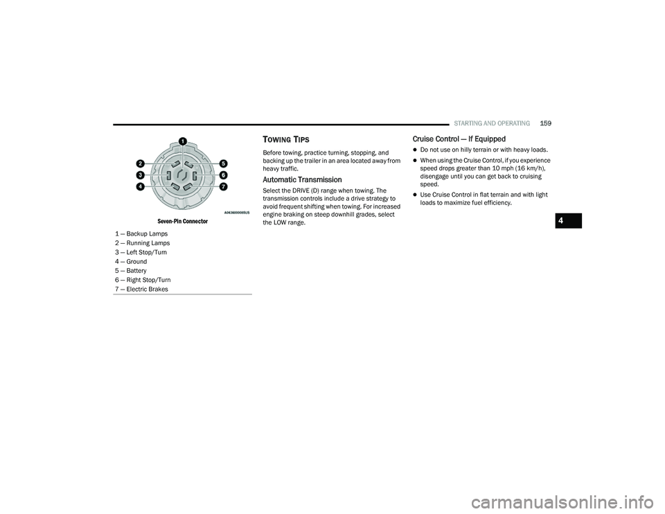
Seven-Pin Connector
TOWING TIPS
Before towing, practice turning, stopping, and
backing up the trailer in an area located away from
heavy traffic.
Automatic Transmission
Select the DRIVE (D) range when towing. The
transmission controls include a drive strategy to
avoid frequent shifting when towing. For increased
engine braking on steep downhill grades, select
the LOW range.
Cruise Control — If Equipped
Do not use on hilly terrain or with heavy loads.
When using the Cruise Control, if you experience
speed drops greater than 10 mph (16 km/h),
disengage until you can get back to cruising
speed.
Use Cruise Control in flat terrain and with light
loads to maximize fuel efficiency.
1 — Backup Lamps
2 — Running Lamps
3 — Left Stop/Turn
4 — Ground
5 — Battery
6 — Right Stop/Turn
7 — Electric Brakes
4
22_MP_OM_EN_USC_t.book Page 159
Page 162 of 344
160STARTING AND OPERATING
RECREATIONAL TOWING (BEHIND MOTORHOME)
TOWING THIS VEHICLE BEHIND ANOTHER VEHICLE
NOTE:
When towing your vehicle, always follow appli -
cable state and provincial laws. Contact state
and provincial Highway Safety offices for addi -
tional details.
You must ensure that the Auto Park Brake
feature is disabled before towing this vehicle, to
avoid inadvertent Electric Park Brake engage -
ment. The Auto Park Brake feature is enabled or
disabled via the Customer Programmable
Features in the Uconnect Settings.
RECREATIONAL TOWING —
F
RONT-WHEEL DRIVE (FWD) MODELS
Recreational towing is allowed ONLY if the front
wheels are OFF the ground. This may be
accomplished using a tow dolly (front wheels off
the ground) or vehicle trailer (all four wheels off the
ground). If using a tow dolly, follow this procedure:
1. Properly secure the dolly to the tow vehicle, following the dolly manufacturer's
instructions.
2. Drive the front wheels onto the tow dolly. 3. Apply the Electric Park Brake (EPB). Place the
transmission in PARK (P). Turn the engine off.
4. Properly secure the front wheels to the dolly, following the dolly manufacturer's instructions.
5. Turn the ignition to the ON/RUN position, but do not start the engine.
6. Press and hold the brake pedal.
7. Release the EPB.
8. Turn the ignition OFF, remove the key fob, and release the brake pedal.
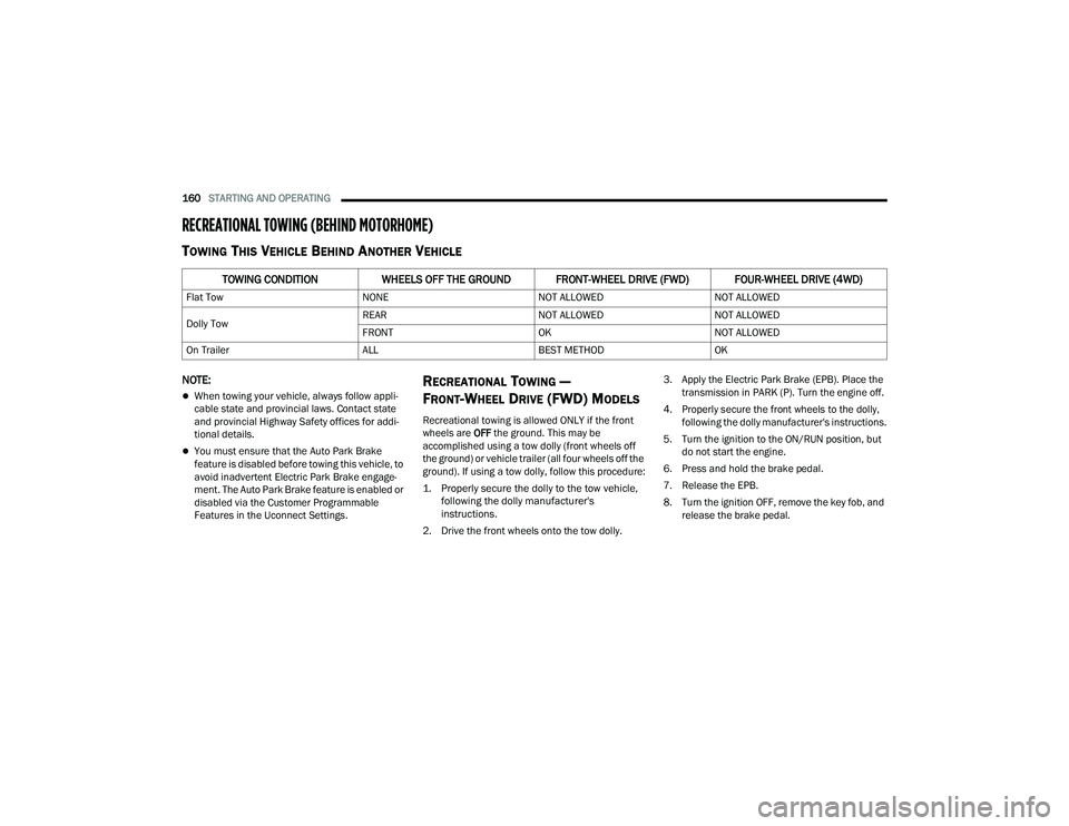
TOWING CONDITION WHEELS OFF THE GROUND FRONT-WHEEL DRIVE (FWD) FOUR-WHEEL DRIVE (4WD)
Flat Tow NONENOT ALLOWEDNOT ALLOWED
Dolly Tow REAR
NOT ALLOWEDNOT ALLOWED
FRONT OKNOT ALLOWED
On Trailer ALLBEST METHODOK
22_MP_OM_EN_USC_t.book Page 160
Page 192 of 344
190SAFETY
(Continued)
ESC Operating Modes
Depending upon model and mode of operation, the
ESC system may have multiple operating modes.
ESC On
This is the normal operating mode for the ESC.
Whenever the vehicle is started, the ESC system
will be in this mode. This mode should be used for
most driving conditions. Alternate ESC modes
should only be used for specific reasons as noted
in the following paragraphs.Partial Off
This mode may be useful if the vehicle becomes
stuck. This mode may modify TCS and ESC
thresholds for activation, which allows for more
wheel spin than normally allowed.
To enter the “Partial Off” mode, momentarily push
the ESC OFF button, located below the radio. The
ESC OFF Indicator Light will illuminate. To turn the
ESC on again, momentarily push the ESC OFF
button and the ESC OFF Indicator Light will turn off.
NOTE:
When driving with snow chains, or when starting off
in deep snow, sand, or gravel, it may be desirable to
allow more wheel spin. This can be accomplished by
momentarily pushing the ESC OFF button to enter
“Partial Off” mode. Once the situation requiring
“Partial Off” mode is overcome, turn ESC back on by
momentarily pushing the ESC OFF button. This may
be done while the vehicle is in motion.
Full Off (Four-Wheel Drive Models Only)
This mode is intended for off-highway or off-road
use when ESC stability features could inhibit
vehicle maneuverability due to trail conditions.
This mode is entered by pushing and holding the
ESC OFF button for five seconds when the vehicle
is stopped and the engine is running. After five
seconds, the ESC OFF Indicator Light will illuminate
and the “ESC OFF” message will appear in the
instrument cluster display.
In this mode, ESC and TCS, except for the “limited
slip” feature described in the TCS section, are
turned off until the vehicle reaches a speed of
40 mph (64 km/h). At 40 mph (64 km/h), the
system returns to “Partial Off” mode, as described
above. TCS remains off. When the vehicle speed
drops below 30 mph (48 km/h), the ESC system
shuts off. ESC is deactivated at low vehicle speeds
so that it will not interfere with off-road driving.
However, ESC function returns to provide the
stability feature at speeds above 40 mph
(64 km/h). The ESC OFF Indicator Light will always
be illuminated when ESC is off.
Vehicle modifications, or failure to properly
maintain your vehicle, may change the
handling characteristics of your vehicle, and
may negatively affect the performance of the
ESC system. Changes to the steering system,
suspension, braking system, tire type and size
or wheel size may adversely affect ESC perfor
-
mance. Improperly inflated and unevenly worn
tires may also degrade ESC performance. Any
vehicle modification or poor vehicle mainte -
nance that reduces the effectiveness of the
ESC system can increase the risk of loss of
vehicle control, vehicle rollover, personal
injury and death.
WARNING!
WARNING!
When in “Partial Off” mode, the TCS function -
ality of ESC, except for the limited slip feature
described in the TCS section, has been
disabled and the ESC OFF Indicator Light will
be illuminated. When in “Partial Off” mode,
the engine power reduction feature of TCS is
disabled, and the enhanced vehicle stability
offered by the ESC system is reduced.
Trailer Sway Control (TSC) is disabled when
the ESC system is in the “Partial Off” mode.
WARNING!
22_MP_OM_EN_USC_t.book Page 190
Page 207 of 344
SAFETY205
Here are some simple steps you can take to
minimize the risk of harm from a deploying air bag:
1. Children 12 years old and under should always ride buckled up in the rear seat of a
vehicle with a rear seat.
2. A child who is not big enough to wear the vehicle seat belt properly must be secured in
the appropriate child restraint or
belt-positioning booster seat in a rear seating
position Ú page 228.
3. If a child from 2 to 12 years old (not in a rear-facing child restraint) must ride in the
front passenger seat, move the seat as far
back as possible and use the proper child
restraint Ú page 228.
4. Never allow children to slide the shoulder belt behind them or under their arm.
5. You should read the instructions provided with your child restraint to make sure that you are
using it properly.
6. All occupants should always wear their lap and shoulder belts properly.
7. The driver and front passenger seats should be moved back as far as practical to allow the
front air bags room to inflate. 8. Do not lean against the door or window. If your
vehicle has side air bags, and deployment
occurs, the side air bags will inflate forcefully
into the space between occupants and the
door and occupants could be injured.
9. If the air bag system in this vehicle needs to be modified to accommodate a disabled person,
see Úpage 325 for customer service contact
information.
SEAT BELT SYSTEMS
Buckle up even though you are an excellent driver,
even on short trips. Someone on the road may be
a poor driver and could cause a collision that
includes you. This can happen far away from home
or on your own street. Research has shown that seat belts save lives, and
they can reduce the seriousness of injuries in a
collision. Some of the worst injuries happen when
people are thrown from the vehicle. Seat belts
reduce the possibility of ejection and the risk of
injury caused by striking the inside of the vehicle.
Everyone in a motor vehicle should be belted at all
times.
Enhanced Seat Belt Use Reminder System
(BeltAlert)
Driver And Passenger BeltAlert — If Equipped
BeltAlert is a feature intended to remind
the driver and outboard front seat
passenger (if equipped with outboard
front passenger seat BeltAlert) to buckle
their seat belts. The BeltAlert feature is active
whenever the ignition switch is in the START or
ON/RUN position.
Initial Indication
If the driver is unbuckled when the ignition switch
is first in the START or ON/RUN position, a chime
will signal for a few seconds. If the driver or
outboard front seat passenger (if equipped with
outboard front passenger seat BeltAlert) is
unbuckled when the ignition switch is first in the
START or ON/RUN position the Seat Belt Reminder
Light will turn on and remain on until both outboard
front seat belts are buckled. The outboard front WARNING!
Never place a rear-facing child restraint in
front of an air bag. A deploying passenger
front air bag can cause death or serious injury
to a child 12 years or younger, including a
child in a rear-facing child restraint.
Never install a rear-facing child restraint in the
front seat of a vehicle. Only use a rear-facing
child restraint in the rear seat. If the vehicle
does not have a rear seat, do not transport a
rear-facing child restraint in that vehicle.
6
22_MP_OM_EN_USC_t.book Page 205
Page 215 of 344
SAFETY213
SUPPLEMENTAL RESTRAINT SYSTEMS
(SRS)
Some of the safety features described in this
section may be standard equipment on some
models, or may be optional equipment on others.
If you are not sure, ask an authorized dealer.
The air bag system must be ready to protect you in
a collision. The Occupant Restraint Controller
(ORC) monitors the internal circuits and
interconnecting wiring associated with the
electrical Air Bag System Components. Your vehicle may be equipped with the following Air
Bag System Components:
Air Bag System Components
Occupant Restraint Controller (ORC)
Air Bag Warning Light
Steering Wheel and Column
Instrument Panel
Knee Impact Bolsters
Driver and Front Passenger Air Bags
Seat Belt Buckle Switch
Supplemental Side Air Bags
Supplemental Knee Air Bags
Front and Side Impact Sensors
Seat Belt Pretensioners
Seat Track Position Sensors
Occupant Classification System
Air Bag Warning Light
The Occupant Restraint Controller (ORC)
monitors the readiness of the electronic
parts of the air bag system whenever the
ignition switch is in the START or ON/RUN
position. If the ignition switch is in the OFF position,
the air bag system is not on and the air bags will
not inflate. The ORC contains a backup power supply system
that may deploy the air bag system even if the
battery loses power or it becomes disconnected
prior to deployment.
The ORC turns on the Air Bag Warning Light in the
instrument panel for approximately four to eight
seconds for a self-check when the ignition switch is
first in the ON/RUN position. After the self-check,
the Air Bag Warning Light will turn off. If the ORC
detects a malfunction in any part of the system, it
turns on the Air Bag Warning Light, either
momentarily or continuously. A single chime will
sound to alert you if the light comes on again after
initial startup.
The ORC also includes diagnostics that will
illuminate the instrument panel Air Bag Warning
Light if a malfunction is detected that could affect
the air bag system. The diagnostics also record the
nature of the malfunction. While the air bag system
is designed to be maintenance free, if any of the
following occurs, have an authorized dealer
service the air bag system immediately.The Air Bag Warning Light does not come on
during the four to eight seconds when the igni
-
tion switch is first in the ON/RUN position.
The Air Bag Warning Light remains on after the
four to eight-second interval.
The Air Bag Warning Light comes on intermit -
tently or remains on while driving.
WARNING!
The seat belt assembly must be replaced if the
switchable Automatic Locking Retractor (ALR)
feature or any other seat belt function is not
working properly when checked according to
the procedures in the Service Manual.
Failure to replace the seat belt assembly
could increase the risk of injury in collisions.
Do not use the Automatic Locking Mode to
restrain occupants who are wearing the seat
belt or children who are using booster seats.
The locked mode is only used to install
rear-facing or forward-facing child restraints
that have a harness for restraining the child.
6
22_MP_OM_EN_USC_t.book Page 213
Page 229 of 344
SAFETY227
(Continued)
Maintaining Your Air Bag System Event Data Recorder (EDR)
This vehicle is equipped with an event data
recorder (EDR). The main purpose of an EDR is to
record, in certain crash or near crash-like
situations, such as an air bag deployment or hitting
a road obstacle, data that will assist in
understanding how a vehicle’s systems performed.
The EDR is designed to record data related to
vehicle dynamics and safety systems for a short
period of time, typically 30 seconds or less.
The EDR in this vehicle is designed to record such
data as:
How various systems in your vehicle were oper-
ating;
Whether or not the driver and passenger safety
belts were buckled/fastened;
How far (if at all) the driver was depressing the
accelerator and/or brake pedal; and,
How fast the vehicle was traveling.
These data can help provide a better
understanding of the circumstances in which
crashes and injuries occur.
WARNING!
Modifications to any part of the air bag system
could cause it to fail when you need it. You
could be injured if the air bag system is not
there to protect you. Do not modify the compo -
nents or wiring, including adding any kind of
badges or stickers to the steering wheel hub
trim cover or the upper passenger side of the
instrument panel. Do not modify the front
fascia/bumper, vehicle body structure, or add
aftermarket side steps or running boards.
It is dangerous to try to repair any part of the
air bag system yourself. Be sure to tell anyone
who works on your vehicle that it has an air
bag system.
Do not attempt to modify any part of your air
bag system. The air bag may inflate acciden -
tally or may not function properly if modifica -
tions are made. Take your vehicle to an
authorized dealer for any air bag system
service. If your seat, including your trim cover
and cushion, needs to be serviced in any way
(including removal or loosening/tightening of
seat attachment bolts), take the vehicle to an
authorized dealer. Only manufacturer
approved seat accessories may be used. If it is
necessary to modify the air bag system for
persons with disabilities, contact an autho -
rized dealer.
WARNING!
6
22_MP_OM_EN_USC_t.book Page 227
Page 244 of 344
242SAFETY
(Continued)
PERIODIC SAFETY CHECKS YOU SHOULD
M
AKE OUTSIDE THE VEHICLE
Tires
Examine tires for excessive tread wear and uneven
wear patterns. Check for stones, nails, glass, or
other objects lodged in the tread or sidewall.
Inspect the tread for cuts and cracks. Inspect
sidewalls for cuts, cracks, and bulges. Check the
lug nut/bolt torque for tightness. Check the tires
(including spare) for proper cold inflation pressure.
Lights
Have someone observe the operation of brake
lights and exterior lights while you work the
controls. Check turn signal and high beam
indicator lights on the instrument panel.
Door Latches
Check for proper closing, latching, and locking.
Fluid Leaks
Check area under the vehicle after overnight
parking for fuel, coolant, oil, or other fluid leaks.
Also, if gasoline fumes are detected or if fuel or
brake fluid leaks are suspected, the cause should
be located and corrected immediately.
ONLY use the driver’s side floor mat on the
driver’s side floor area. To check for interfer -
ence, with the vehicle properly parked with the
engine off, fully depress the accelerator, the
brake, and the clutch pedal (if present) to
check for interference. If your floor mat inter -
feres with the operation of any pedal, or is not
secure to the floor, remove the floor mat from
the vehicle and place the floor mat in your
trunk.
ONLY use the passenger’s side floor mat on
the passenger’s side floor area.
ALWAYS make sure objects cannot fall or slide
into the driver’s side floor area when the
vehicle is moving. Objects can become
trapped under accelerator, brake, or clutch
pedals and could cause a loss of vehicle
control.
WARNING!
NEVER place any objects under the floor mat
(e.g., towels, keys, etc.). These objects could
change the position of the floor mat and may
cause interference with the accelerator,
brake, or clutch pedals.
If the vehicle carpet has been removed and
re-installed, always properly attach carpet to
the floor and check the floor mat fasteners are
secure to the vehicle carpet. Fully depress
each pedal to check for interference with the
accelerator, brake, or clutch pedals then
re-install the floor mats.
It is recommended to only use mild soap and
water to clean your floor mats. After cleaning,
always check your floor mat has been properly
installed and is secured to your vehicle using
the floor mat fasteners by lightly pulling mat.
WARNING!
22_MP_OM_EN_USC_t.book Page 242
Page 252 of 344
250IN CASE OF EMERGENCY
(Continued)
JACKING INSTRUCTIONS
Jack Warning Label
1. Remove the spare tire, jack, and wheel bolt wrench.
2. If equipped with aluminum wheels where the center cap covers the wheel bolts, use the
wheel bolt wrench to pry the center cap off
carefully before raising the vehicle. 3. Before raising the vehicle, use the wheel bolt
wrench to loosen, but not remove, the wheel
bolts on the wheel with the flat tire. Turn the
wheel bolts counterclockwise one turn while
the wheel is still on the ground.
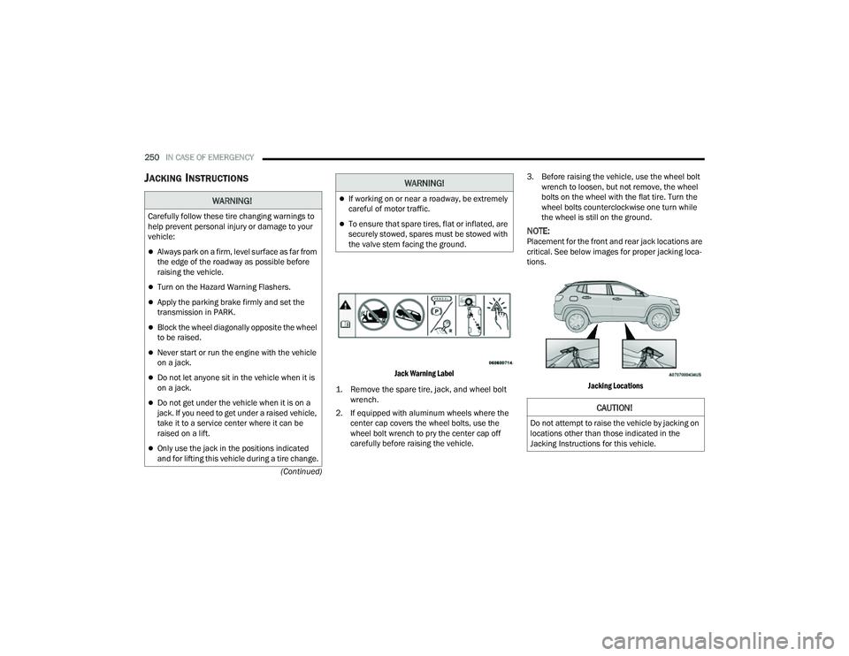
NOTE:Placement for the front and rear jack locations are
critical. See below images for proper jacking loca -
tions.
Jacking Locations
WARNING!
Carefully follow these tire changing warnings to
help prevent personal injury or damage to your
vehicle:
Always park on a firm, level surface as far from
the edge of the roadway as possible before
raising the vehicle.
Turn on the Hazard Warning Flashers.
Apply the parking brake firmly and set the
transmission in PARK.
Block the wheel diagonally opposite the wheel
to be raised.
Never start or run the engine with the vehicle
on a jack.
Do not let anyone sit in the vehicle when it is
on a jack.
Do not get under the vehicle when it is on a
jack. If you need to get under a raised vehicle,
take it to a service center where it can be
raised on a lift.
Only use the jack in the positions indicated
and for lifting this vehicle during a tire change.
If working on or near a roadway, be extremely
careful of motor traffic.
To ensure that spare tires, flat or inflated, are
securely stowed, spares must be stowed with
the valve stem facing the ground.
WARNING!
CAUTION!
Do not attempt to raise the vehicle by jacking on
locations other than those indicated in the
Jacking Instructions for this vehicle.
22_MP_OM_EN_USC_t.book Page 250