light JEEP GLADIATOR 2023 Owner's Guide
[x] Cancel search | Manufacturer: JEEP, Model Year: 2023, Model line: GLADIATOR, Model: JEEP GLADIATOR 2023Pages: 448, PDF Size: 17.37 MB
Page 73 of 448
GETTING TO KNOW YOUR VEHICLE71
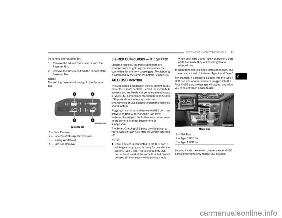
To remove the Fastener Bin:
1. Remove the lid and foam inserts from the Fastener Bin.
2. Remove the three nuts from the bottom of the Fastener Bin.
NOTE:The soft top fasteners do not go in the Fastener
Bin.
Fastener Bin
LIGHTED CUPHOLDERS — IF EQUIPPED
On some vehicles, the front cupholders are
equipped with a light ring that illuminates the
cupholders for the front passengers. The light ring
is controlled by the Dimmer Controls Ú page 60.
AUX/USB CONTROL
The Media Hub is located on the instrument panel,
below the climate controls. Behind the media hub
access door, the Media Hub contains one AUX port,
a Type C USB port and one standard USB port. Both
USB ports allow you to play music from
smartphones or USB devices through the vehicle’s
sound system.
Plugging in a smartphone device to a USB port may
activate Android Auto™ or Apple CarPlay®
features, if equipped. For further information, refer
to the Owner’s Manual Supplement or
Úpage 254.
The Smart Charging USB ports provide power to
your device up to an hour after the vehicle is turned
off.
NOTE:
Once a device is connected to the USB port, it
will begin charging and is ready for use with the
system. Type C and Type A charge-only USB
ports can be used at the same time but cannot
be used simultaneously while playing media. When both Type C and Type A charge-only USB
ports are in use they will be charged at a
reduced rate.
Both ports share a single data connection. The
user cannot switch between Type A and Type C.
For example, if a device is plugged into the Type A
USB port and another device is plugged into the
Type C USB port, a message will appear and allow
you to select which device to use.
Media Hub
Located inside the center console, a second USB
port allows you to only charge USB devices.
1 — Door Removal
2 — Under Seat Storage Bin Removal
3 — Folding Windshield
4 — Hard Top Removal
1 — AUX Port
2 — Type C USB Port
3 — Type A USB Port
2
23_JT_OM_EN_USC_t.book Page 71
Page 75 of 448
GETTING TO KNOW YOUR VEHICLE73
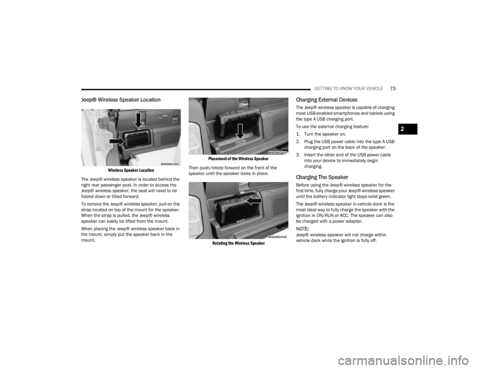
Jeep® Wireless Speaker Location
Wireless Speaker Location
The Jeep® wireless speaker is located behind the
right rear passenger seat. In order to access the
Jeep® wireless speaker, the seat will need to be
folded down or tilted forward.
To remove the Jeep® wireless speaker, pull on the
strap located on top of the mount for the speaker.
When the strap is pulled, the Jeep® wireless
speaker can easily be lifted from the mount.
When placing the Jeep® wireless speaker back in
the mount, simply put the speaker back in the
mount.
Placement of the Wireless Speaker
Then push/rotate forward on the front of the
speaker until the speaker locks in place.
Rotating the Wireless Speaker
Charging External Devices
The Jeep® wireless speaker is capable of charging
most USB-enabled smartphones and tablets using
the type A USB charging port.
To use the external charging feature:
1. Turn the speaker on.
2. Plug the USB power cable into the type A USB charging port on the back of the speaker.
3. Insert the other end of the USB power cable into your device to immediately begin
charging.
Charging The Speaker
Before using the Jeep® wireless speaker for the
first time, fully charge your Jeep® wireless speaker
until the battery indicator light stays solid green.
The Jeep® wireless speaker in-vehicle dock is the
most ideal way to fully charge the speaker with the
ignition in ON/RUN or ACC. The speaker can also
be charged with a power adapter.
NOTE:Jeep® wireless speaker will not charge within
vehicle dock while the ignition is fully off.
2
23_JT_OM_EN_USC_t.book Page 73
Page 76 of 448
74GETTING TO KNOW YOUR VEHICLE
To charge the Jeep® wireless speaker with a
power adapter, insert the power adapter into a wall
outlet. Next, plug the power adapter into the Jeep®
wireless speaker charging port on the back of the
speaker.
NOTE:
Power adapter needed for the Jeep® wireless
speaker has to have a range of 14 VDC to 16.5 VDC,
with a minimum of 2.7A and a barrel connector
dimension of 5.5 mm by 2.5 mm. Power adapter is
not included.
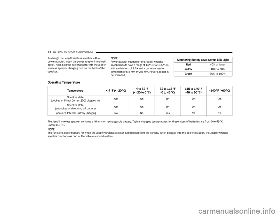
Operating Temperature
The Jeep® wireless speaker contains a lithium-ion rechargeable battery. Typical charging temperatures for these types of batteries are from 0 to 45°C
(32 to 113°F).
NOTE:The functions described are for when the Jeep® wireless speaker is undocked from the vehicle. When plugged into the docking station, the Jeep® wireless
speaker functions as part of the vehicle’s sound system.
Monitoring Battery Level Status LED Light
Red 40% or lower
Yellow 40% to 70%
Green 70% to 100%
Temperature <-4°F (< -20°C)-4 to 32°F
(< -20 to 0°C) 32 to 113°F
(0 to 45°C) 115 to 140°F
(46 to 60°C) >140°F (>60°C)
Speaker state
(docked or Direct Current [DC] plugged in) Off
OnOnOnOff
Speaker state
(undocked and running off battery) Off
OnOnOnOff
Speaker’s Internal Battery Charging NoNoYes NoNo
23_JT_OM_EN_USC_t.book Page 74
Page 78 of 448
76GETTING TO KNOW YOUR VEHICLE
Waterproof Features
The Jeep® wireless speaker is IP67 waterproof
certified with design in mind to withstand rainfall,
waterjets, splashing and being submerged in up to
3 ft (1 m) of water for up to 30 minutes.
Warnings, Caution & Legal Information
To reduce the risk of fire or electric shock, do not
expose the Jeep® wireless speaker to rain or
moisture while charging. The Jeep® wireless
speaker should not be exposed to dripping or
splashing, and objects filled with liquids, such as
vases, should not be placed on or near it while
being charged or charging other devices. As with
any electronic products, use care not to spill liquids
into any part of the product. Liquids can cause a
failure and/or a fire hazard. The power supply must
be used indoors only. Make no modifications to the
product or accessories. Unauthorized alterations
may compromise safety, regulatory compliance,
and system performance, and will void the
warranty. Do not place any flame sources, such as
lighted candles, on or near the Jeep® wireless speaker. The Jeep® wireless speaker contains
small parts that may be a choking hazard and is
not suitable for children under age 3. Do not
continue charging the battery if it does not reach
full charge within the specified charging time.
Overcharging may cause the battery to become
hot, rupture, or ignite. If you see any heat
deformation or leakage, properly dispose of the
battery. Do not attempt to charge the battery in
temperatures outside the range of 32°- 104°F
(0° - 40°C). If the battery begins to leak, do not
allow the liquid to come in contact with your skin or
eyes. If contact has been made, wash the affected
area with plenty of water and seek medical
attention immediately. Do not expose the Jeep®
wireless speaker or battery to excessive heat,
including direct sunlight or fire. Do not store or use
inside cars in hot weather, where it can be exposed
to temperatures in excess of 115°F (60°C). Doing
so may cause the battery and power supply to
generate heat, rupture, or ignite. Using the Jeep®
wireless speaker in this manner also may result in
a loss of performance and a shortened life
expectancy. Extended exposure to direct sunlight
may damage the external appearance and
material qualities. Do not step on, throw, or drop
batteries or the power supply or device, or expose
them to a strong shock. Do not pierce, crush, dent,
or deform the batteries or power supply in any way.
If either becomes deformed, properly dispose of it.
Do not short-circuit batteries. Do not attempt to service the Jeep® wireless speaker yourself.
Opening or removing covers may expose you to
dangerous voltages or other hazards and will void
the manufacturer’s warranty. To prevent risk of fire
or electric shock, avoid overloading wall outlets,
extension cords, or integral convenience
receptacles. Your Bluetooth® device (mobile
phone, music player, tablet, laptop, etc.) must
support the A2DP Bluetooth® profile in order to
work wirelessly with your Jeep® wireless speaker.
The A2DP profile is supported by most recent
mobile products with built-in Bluetooth®
capability. Please refer to your device’s user
manual for details and instruction regarding the
Bluetooth® profiles it supports. This device
complies with part 15 of the FCC Rules. Operation
is subject to the following two conditions: (1) This
device may not cause harmful interference, and
(2) this device must accept any interference
received, including interference that may cause
undesired operation.
Jeep® follows Safety Instruction for CE- LV. Do not
operate products in temperatures outside the
range of -5 to 40°C. Operating Frequency Band:
2402 MHz to 2480 MHz. Maximum RF power:
6 dBm EIRP. Do not install this equipment in a
confined space or building, such as a bookcase or
similar unit that is not well-ventilated. The
ventilation should not be impeded by covering the
ventilation openings with items such as
newspaper, tablecloths, curtains etc.
WARNING!
Any modifications or alterations to this vehicle
could seriously affect its roadworthiness and
safety and may lead to a collision resulting in
serious injury or death.
23_JT_OM_EN_USC_t.book Page 76
Page 80 of 448
78GETTING TO KNOW YOUR VEHICLE
(Continued)
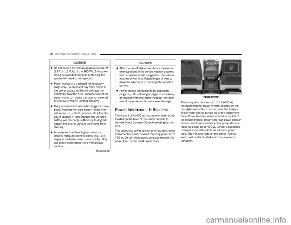
POWER INVERTERS — IF EQUIPPED
There is a 115 V (400 W) maximum inverter outlet
located on the back of the center console to
convert Direct Current (DC) to Alternating Current
(AC).
This outlet can power cellular phones, electronics
and other low power devices requiring power up to
400 W. Certain video game consoles exceed this
power limit, as will most power tools.
Power Inverter
There may also be a second 115 V (400 W)
maximum exterior power inverter located on the
rear right side of the truck bed near the tailgate.
This inverter can be turned on by the Instrument
Panel Power Inverter switch located to the left of
the steering wheel. This inverter can power cellular
phones, electronics and other low power devices
requiring power up to 400 W. Certain video game
consoles exceed this limit, as will most power
tools. The indicator light on the power inverter
switch will be illuminated when the inverter is
turned on.
CAUTION!
Do not exceed the maximum power of 160 W
(13 A) at 12 Volts. If the 160 W (13 A) power
rating is exceeded, the fuse protecting the
system will need to be replaced.
Power outlets are designed for accessory
plugs only. Do not insert any other object in
the power outlets as this will damage the
outlet and blow the fuse. Improper use of the
power outlet can cause damage not covered
by your New Vehicle Limited Warranty.
Many accessories that can be plugged in draw
power from the vehicle's battery, even when
not in use (i.e., cellular phones, etc.). Eventu -
ally, if plugged in long enough, the vehicle's
battery will discharge sufficiently to degrade
battery life and/or prevent the engine from
starting.
Accessories that draw higher power (i.e.,
coolers, vacuum cleaners, lights, etc.), will
degrade the battery even more quickly. Only
use these intermittently and with greater
caution.
After the use of high power draw accessories,
or long periods of the vehicle not being started
(with accessories still plugged in), the vehicle
must be driven a sufficient length of time to
allow the alternator to recharge the vehicle's
battery.
Power outlets are designed for accessory
plugs only. Do not hang any type of accessory
or accessory bracket from the plug. Improper
use of the power outlet can cause damage.
CAUTION!
23_JT_OM_EN_USC_t.book Page 78
Page 111 of 448
GETTING TO KNOW YOUR VEHICLE109
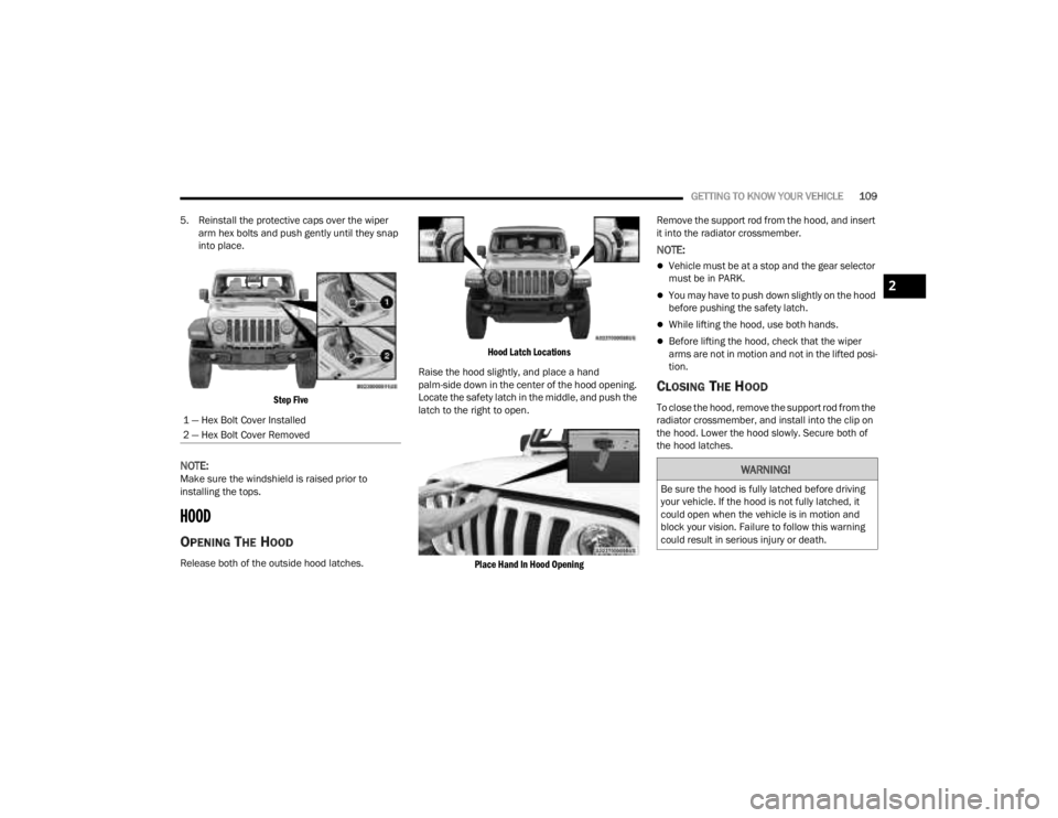
5. Reinstall the protective caps over the wiper arm hex bolts and push gently until they snap
into place.
Step Five
NOTE:Make sure the windshield is raised prior to
installing the tops.
HOOD
OPENING THE HOOD
Release both of the outside hood latches.
Hood Latch Locations
Raise the hood slightly, and place a hand
palm-side down in the center of the hood opening.
Locate the safety latch in the middle, and push the
latch to the right to open.
Place Hand In Hood Opening
Remove the support rod from the hood, and insert
it into the radiator crossmember.
NOTE:
Vehicle must be at a stop and the gear selector
must be in PARK.
You may have to push down slightly on the hood
before pushing the safety latch.
While lifting the hood, use both hands.
Before lifting the hood, check that the wiper
arms are not in motion and not in the lifted posi
-
tion.
CLOSING THE HOOD
To close the hood, remove the support rod from the
radiator crossmember, and install into the clip on
the hood. Lower the hood slowly. Secure both of
the hood latches.
1 — Hex Bolt Cover Installed
2 — Hex Bolt Cover Removed
WARNING!
Be sure the hood is fully latched before driving
your vehicle. If the hood is not fully latched, it
could open when the vehicle is in motion and
block your vision. Failure to follow this warning
could result in serious injury or death.
2
23_JT_OM_EN_USC_t.book Page 109
Page 127 of 448
GETTING TO KNOW YOUR INSTRUMENT PANEL125
ACC SET
When ACC is set, the set speed will display in the
instrument cluster.
The ACC screen may display once again if any ACC
activity occurs, which may include any of the
following:
System Cancel
Driver Override
System Off
ACC Proximity Warning
ACC Unavailable Warning
NOTE:The instrument cluster display will return to the last
display selected after five seconds of no ACC
display activity Ú page 175.
Fuel Economy
Push and release the up or down arrow
button until the Fuel Economy icon is highlighted in
the instrument cluster display. Push and hold the
OK button to reset average fuel economy feature.
Toggle left or right to select a display with or
without Current Fuel Economy Information.
Range – The display shows the estimated
distance (mi or km) that can be traveled with the
fuel remaining in the tank. When the Range
value is less than 10 miles (16 km), the Range
display will change to a “LOW” message. Adding a significant amount of fuel to the vehicle will
turn off the “LOW” message and a new Range
value will display. Range cannot be reset
through the
OK button.
NOTE:Significant changes in driving style or vehicle
loading will greatly affect the actual drivable
distance of the vehicle, regardless of the Range
displayed value.
Average – The display shows the average fuel
economy (MPG, L/100km, or km/L) since the
last reset.
Current – The display shows the current fuel
economy (MPG, L/100km, or km/L) while
driving.
Trip
Push and release the up or down arrow
button until the Trip icon/title is highlighted in the
instrument cluster display, then push and release
the left or right arrow button to select Trip A
or Trip B.
The Trip A and Trip B information will display the
following:
Distance
Average Fuel Economy
Elapsed Time
Hold the OK button to reset all the information.
Stop/Start — If Equipped
Push and release the up or down arrow
button until the Stop/Start icon/title is highlighted
in the instrument cluster display. The screen will
display the Stop/Start status.
Audio
Push and release the up or down arrow
button until the Stop/Start icon/title is highlighted
in the instrument cluster display. The screen will
display the Stop/Start status.
Phone Call Status
When a call is incoming, a Phone Call Status
pop-up will display on the screen. The pop-up will
remain until the phone is answered or ignored.
NOTE:The call status will temporarily replace the
previous media source information displayed on
the screen. When the pop-up is no longer
displayed, the display will return to the last used
screen.
Stored Messages
Push and release the up or down arrow
button until the Messages Menu item is
highlighted. This feature shows the number of
stored warning messages. Pushing the right
arrow button will allow you to see what the stored
messages are.
3
23_JT_OM_EN_USC_t.book Page 125
Page 128 of 448
126GETTING TO KNOW YOUR INSTRUMENT PANEL
When no messages are present, main menu icon
will be a closed envelope, and “No Stored
Messages” will display.
Screen Setup
NOTE:The Screen Setup feature can only be used while
the vehicle is not in motion.
Push and release the up or down arrow
button until the Screen Setup Menu Icon/Title is
highlighted in the instrument cluster display. Push
and release the OK button to enter the submenus
and follow the prompts on the screen as needed.
The Screen Setup feature allows you to change
what information is displayed in the instrument
cluster as well as the location in which that
information is displayed.
Screen Setup Driver Selectable Items Gear Display — If Equipped
Full
Single
Current Gear
Off
On
Odometer
Show
Hide
Defaults
Cancel
Restore
Upper Left
None Time Current Econ
Compass Range to
EmptyTrip A Distance
Outside Temp Average Econ Trip B Distance
Upper Right
None Time Current Econ
Compass Range to
EmptyTrip A Distance
Outside Temp Average Econ Trip B Distance
Upper Center
None Time Current Econ
Compass Range to
EmptyTrip A Distance
Audio Average Econ Trip B Distance
Outside Temp Menu Title Speedometer
Favorite Menus
Speedometer Vehicle Info Off Road —
If Equipped
(show/hide)
Driver Assist —
If Equipped
(show/hide) Fuel Economy
(show/hide)
Trip Info
(show/hide)
Stop / Start —
If EquippedAudio
(show/hide)
Messages
Screen Setup Vehicle
Settings —
If Equipped
Favorite Menus
23_JT_OM_EN_USC_t.book Page 126
Page 129 of 448
GETTING TO KNOW YOUR INSTRUMENT PANEL127
BATTERY SAVER ON, BATTERY SAVER
M
ODE MESSAGE, AND ELECTRICAL
L
OAD REDUCTION ACTIONS
(I
F EQUIPPED)
This vehicle is equipped with an Intelligent Battery
Sensor (IBS) to perform additional monitoring of
the electrical system and status of the vehicle
battery.
In cases when the IBS detects charging system
failure, or the vehicle battery conditions are
deteriorating, electrical load reduction actions will
take place to extend the driving time and distance
of the vehicle. This is done by reducing power to or
turning off non-essential electrical loads.
Load reduction is only active when the engine is
running. It will display a message if there is a risk
of battery depletion to the point where the vehicle
may stall due to lack of electrical supply, or will not
restart after the current drive cycle.
When load reduction is activated, the message
“Battery Saver On Some Systems May Have
Reduced Power” will appear in the instrument
cluster. These messages indicate the vehicle battery has a
low state of charge and continues to lose electrical
charge at a rate that the charging system cannot
sustain.
NOTE:
The charging system is independent from load
reduction. The charging system performs a diag
-
nostic on the charging system continuously.
If the Battery Charge Warning Light is on it may
indicate a problem with the charging system
Ú page 133.
The electrical loads that may be switched off (if
equipped), and vehicle functions which can be
affected by load reduction:
Heated Seat/Vented Seats/Heated Wheel
Rear Defroster And Heated Mirrors
HVAC System
115 Volt AC Power Inverter System
Audio and Telematics System
Loss of battery charge may indicate one or more of
the following conditions:
The charging system cannot deliver enough
electrical power to the vehicle system because
the electrical loads are larger than the capability
of the charging system. The charging system is
still functioning properly.
Turning on all possible vehicle electrical loads
(e.g. HVAC to max settings, exterior and interior
lights, overloaded power outlets +12 Volt,
115 Volt AC, USB ports) during certain driving
conditions (city driving, towing, frequent stop -
ping).
Installing options like additional lights, upfitter
electrical accessories, audio systems, alarms
and similar devices.
Unusual driving cycles (short trips separated by
long parking periods).
The vehicle was parked for an extended period
of time (weeks, months).
The battery was recently replaced and was not
charged completely.
The battery was discharged by an electrical load
left on when the vehicle was parked.
The battery was used for an extended period
with the engine not running to supply radio,
lights, chargers, +12 Volt portable appliances
like vacuum cleaners, game consoles and
similar devices.
3
23_JT_OM_EN_USC_t.book Page 127
Page 130 of 448
128GETTING TO KNOW YOUR INSTRUMENT PANEL
What to do when an electrical load reduction
action message is present (“Battery Saver On” or
“Battery Saver Mode”)
During a trip:
Reduce power to unnecessary loads if possible:
Turn off redundant lights (interior or exte -
rior)
Check what may be plugged in to power
outlets +12 Volt, 115 Volts AC, USB ports
Check HVAC settings (blower, temperature)
Check the audio settings (volume)
After a trip:
Check if any aftermarket equipment was
installed (additional lights, upfitter electrical
accessories, audio systems, alarms) and review
specifications if any (load and ignition off draw
currents).
Evaluate the latest driving cycles (distance,
driving time and parking time).
The vehicle should have service performed if
the message is still present during consecutive
trips and the evaluation of the vehicle and
driving pattern did not help to identify the cause.
DIESEL DISPLAYS
When the appropriate conditions exist, the
following messages display in the instrument
cluster display:
Exhaust Filter Nearing Full Safely Drive at
Consistent Speeds to Clear
Exhaust Filter Full – Power Reduced See Dealer
Exhaust System Service Required – See Dealer
Exhaust System – Filter XX% Full Service
Required See Dealer
Exhaust System Regeneration in Process
Continue Driving
Exhaust System – Regeneration Completed
DIESEL PARTICULATE FILTER (DPF)
M
ESSAGES
This engine meets all required diesel engine
emissions standards. To achieve these emissions
standards, your vehicle is equipped with a
state-of-the-art engine and exhaust system. These
systems are seamlessly integrated into your
vehicle and managed by the Powertrain Control
Module (PCM). The PCM manages engine combustion to allow the exhaust system’s catalyst
to trap and burn Particulate Matter (PM)
pollutants, with no input or interaction on your part.
WARNING!
A malfunctioning catalytic converter, as
previously referenced, can reach higher
temperatures than in normal operating
conditions. This can cause a fire if you drive
slowly or park over flammable substances such
as dry plants, wood, cardboard, etc. This could
result in death or serious injury to the driver,
occupants or others.
CAUTION!
The engine may be switched off even if the
warning light is on: repeated interruptions of the
regeneration process could cause an early
deterioration of engine oil. For this reason it is
always advisable to wait for the symbol to go off
before turning off the engine, following the
previously mentioned instructions. Do not
complete the DPF regeneration process when
the vehicle is stopped.
23_JT_OM_EN_USC_t.book Page 128