light JEEP GLADIATOR 2023 Owner's Manual
[x] Cancel search | Manufacturer: JEEP, Model Year: 2023, Model line: GLADIATOR, Model: JEEP GLADIATOR 2023Pages: 448, PDF Size: 17.37 MB
Page 55 of 448

GETTING TO KNOW YOUR VEHICLE53
To operate HomeLink®, push and release any
of the programmed HomeLink® buttons. These
buttons will activate the devices they are
programmed to with each press of the corre -
sponding HomeLink® button.
The HomeLink® indicator light is located above
the center button.
NOTE:HomeLink® is disabled when the Vehicle Security
system is active Ú page 432.
BEFORE YOU BEGIN PROGRAMMING
H
OMELINK®
For efficient programming and accurate
transmission of the radio-frequency signal, it is
recommended that a new battery be placed in the
hand-held transmitter of the device that is being
programmed to the HomeLink® system. Make
sure your hand-held transmitter is programmed to
activate the device you are trying to program your
HomeLink® button to.
Ensure that your vehicle is parked outside of the
garage before you begin programming.
It is recommended that you erase all the channels
of your HomeLink® before you use it for the first
time.
ERASING ALL THE HOMELINK®
C
HANNELS
To erase the channels, follow this procedure:
1. Place the ignition switch into the ON/RUN
position.
2. Push and hold the two outside HomeLink® buttons (I and III) for up to 20 seconds, or until
the HomeLink® indicator light flashes.
NOTE:Erasing all channels should only be performed
when programming HomeLink® for the first time.
Do not erase channels when programming addi -
tional buttons.
IDENTIFYING WHETHER YOU HAVE A
R
OLLING CODE OR NON-ROLLING CODE
D
EVICE
Before programming a device to one of your
HomeLink® buttons, you must determine whether
the device has a rolling code or non-rolling code.
Rolling Code Devices
To determine if your device has a rolling code, a
good indicator is its manufacturing date. Typically,
devices manufactured after 1995 have rolling
codes. A device with a rolling code will also have a
“LEARN” or “TRAIN” button located where the antenna is attached to the device. The button may
not be immediately visible when looking at the
device. The name and color of the button may vary
slightly by manufacturer.
NOTE:The “LEARN” or “TRAIN” button is not the button
you normally use to operate the device.
Non-rolling Code Devices
Most devices manufactured before 1995 will not
have a rolling code. These devices will also not
have a “LEARN” or “TRAIN” button.
PROGRAMMING HOMELINK® TO A
G
ARAGE DOOR OPENER
To program any of the HomeLink® buttons to
activate your garage door opener motor, proceed
as follows:
NOTE:All HomeLink® buttons are programmed using this
procedure. You do not need to erase all channels
when programming additional buttons.
1. Place the ignition switch into the ON/RUN
position.
2. Place the garage door opener transmitter 1 to 3 inches (3 to 8 cm) away from the
HomeLink® button you wish to program, while
keeping the HomeLink® indicator light in view.
2
23_JT_OM_EN_USC_t.book Page 53
Page 56 of 448
54GETTING TO KNOW YOUR VEHICLE
(Continued)
3. Push and hold the HomeLink® button you
want to program while you push and hold the
garage door opener transmitter button you are
trying to replicate.
4. Continue to hold both buttons and observe the HomeLink® indicator light. The HomeLink®
indicator light will flash slowly and then rapidly.
Once this happens, release both buttons.
NOTE:Make sure the garage door opener motor is
plugged in before moving on to the rolling code/
non-rolling code final steps.
Rolling Code Garage Door Opener Final Steps
NOTE:You have 30 seconds in which to initiate rolling
code final step 2, after completing rolling code
final step 1.
1. At the garage door opener motor (in the garage), locate the “LEARN” or “TRAIN”
button. This can usually be found where the
hanging antenna wire is attached to the
garage door opener motor. Firmly push and
release the “LEARN” or “TRAIN” button.
2. Return to the vehicle and push the programmed HomeLink® button three times
(holding the button for two seconds each
time). If the garage door opener motor
operates, programming is complete. 3. Push the programmed HomeLink® button to
confirm that the garage door opener motor
operates. If the garage door opener motor
does not operate, repeat the final steps for the
rolling code procedure.
Non-Rolling Code Garage Door Opener Final Steps
1. Push and hold the programmed HomeLink® button and observe the HomeLink® indicator
light. If the HomeLink® indicator light stays
on constantly, programming is complete.
2. Push the programmed HomeLink® button to confirm that the garage door opener motor
operates. If the garage door opener motor
does not operate, repeat the steps from the
beginning.
PROGRAMMING HOMELINK® TO A
M
ISCELLANEOUS DEVICE
The procedure on how to program HomeLink® to a
miscellaneous device follows the same procedure
as programming to a garage door opener
Ú page 53. Be sure to determine if the device has
a rolling code, or non-rolling code before beginning
the programming process.
NOTE:Canadian radio frequency laws require transmitter
signals to time-out (or quit) after several seconds
of transmission, which may not be long enough for
HomeLink® to pick up the signal during
programming. Similar to this Canadian law, some
U.S. gate operators are designed to time-out in the
same manner. The procedure may need to be
performed multiple times to successfully pair the
device to your HomeLink® buttons.
WARNING!
Your motorized door or gate will open and
close while you are programming the universal
transceiver. Do not program the transceiver if
people or pets are in the path of the door or
gate.
Do not run your vehicle in a closed garage or
confined area while programming the trans -
ceiver. Exhaust gas from your vehicle contains
carbon monoxide which is odorless and color -
less. Carbon monoxide is poisonous when
inhaled and can cause you and others to be
severely injured or killed.
WARNING!
23_JT_OM_EN_USC_t.book Page 54
Page 57 of 448

GETTING TO KNOW YOUR VEHICLE55
REPROGRAMMING A SINGLE
H
OMELINK® BUTTON
To reprogram a single HomeLink® button that has
been previously trained, without erasing all the
channels, proceed as follows. Be sure to
determine whether the new device you want to
program the HomeLink® button to has a rolling
code, or non-rolling code.
1. Place the ignition in the ON/RUN position,
without starting the engine.
2. Push and hold the desired HomeLink® button until the HomeLink® Indicator light begins to
flash after 20 seconds. Do not release the
button.
3. Without releasing the button , proceed with
Step 2 in “Programming HomeLink® To A
Garage Door Opener” and follow all remaining
steps.
CANADIAN/GATE OPERATOR
P
ROGRAMMING
For programming transmitters in Canada/United
States that require the transmitter signals to
“time-out” after several seconds of transmission,
see the following. Canadian Radio Frequency (RF) laws require
transmitter signals to time-out (or quit) after
several seconds of transmission – which may not
be long enough for HomeLink® to pick up the
signal during programming. Similar to this
Canadian law, some US gate operators are
designed to time-out in the same manner.
It may be helpful to unplug the device during the
cycling process to prevent possible overheating of
the garage door or gate motor.
1. Place the ignition in the ON/RUN position.
2. Place the hand-held transmitter 1 to 3 inches
(3 to 8 cm) away from the HomeLink® button
you wish to program while keeping the
HomeLink® indicator light in view.
3. Continue to press and hold the HomeLink® button, while you press and release (cycle)
your hand-held transmitter every two seconds
until HomeLink® has successfully accepted
the frequency signal. The indicator light will
flash slowly and then rapidly when fully
trained.
4. Watch for the HomeLink® indicator to change flash rates. When it changes, it is
programmed. It may take up to 30 seconds or
longer in rare cases. The garage door may
open and close while you are programming. 5. Press and hold the programmed HomeLink®
button and observe the indicator light.
NOTE:
If the indicator light stays on constantly,
programming is complete and the garage
door/device should activate when the
HomeLink® button is pressed.
To program the two remaining HomeLink®
buttons, repeat each step for each
remaining button. DO NOT erase the chan -
nels.
If you unplugged the garage door opener/device
for programming, plug it back in at this time.
Reprogramming A Single HomeLink® Button
(Canadian/Gate Operator)
To reprogram a channel that has been previously
trained, follow these steps:
1. Place the ignition in the ON/RUN position.
2. Press and hold the desired HomeLink® button until the indicator light begins to flash after
20 seconds. Do not release the button.
3. Without releasing the button, proceed with “Canadian/Gate Operator Programming”
step 2 and follow all remaining steps.
2
23_JT_OM_EN_USC_t.book Page 55
Page 58 of 448
56GETTING TO KNOW YOUR VEHICLE
SECURITY
It is advised to erase all channels before you sell or
turn in your vehicle.
To do this, push and hold the two outside buttons
for 20 seconds until the indicator flashes. Note
that all channels will be erased. Individual
channels cannot be erased.
The HomeLink® Universal Transceiver is disabled
when the Vehicle Security system is active.
NOTE:The universal garage door opener only operates
when the engine is running for security reasons
associated with removable tops and doors.
TROUBLESHOOTING TIPS
If you are having trouble programming
HomeLink®, here are some of the most common
solutions:
Replace the battery in the garage door opener
hand-held transmitter.
Push the LEARN button on the garage door
opener to complete the training for a rolling code.
Did you unplug the device for programming and
remember to plug it back in? If you have any problems, or require assistance,
please call toll-free 1-800-355-3515 or, on the
Internet at HomeLink.com for information or
assistance.
EXTERIOR LIGHTS
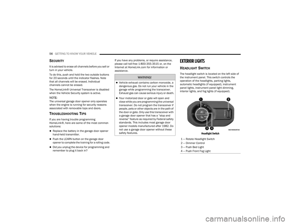
HEADLIGHT SWITCH
The headlight switch is located on the left side of
the instrument panel. This switch controls the
operation of the headlights, parking lights,
automatic headlights (if equipped), instrument
panel lights, instrument panel light dimming,
interior lights, and fog lights (if equipped).
Headlight Switch
WARNING!
Vehicle exhaust contains carbon monoxide, a
dangerous gas. Do not run your vehicle in the
garage while programming the transceiver.
Exhaust gas can cause serious injury or death.
Your motorized door or gate will open and
close while you are programming the universal
transceiver. Do not program the transceiver if
people, pets or other objects are in the path of
the door or gate. Only use this transceiver with
a garage door opener that has a “stop and
reverse” feature as required by Federal safety
standards. This includes most garage door
opener models manufactured after 1982. Do
not use a garage door opener without these
safety features.
1 — Rotate Headlight Switch
2 — Dimmer Control
3 — Push Bed Light
4 — Push Front Fog Light
23_JT_OM_EN_USC_t.book Page 56
Page 59 of 448
GETTING TO KNOW YOUR VEHICLE57
Headlight Switch (Vehicles Sold In Canada)
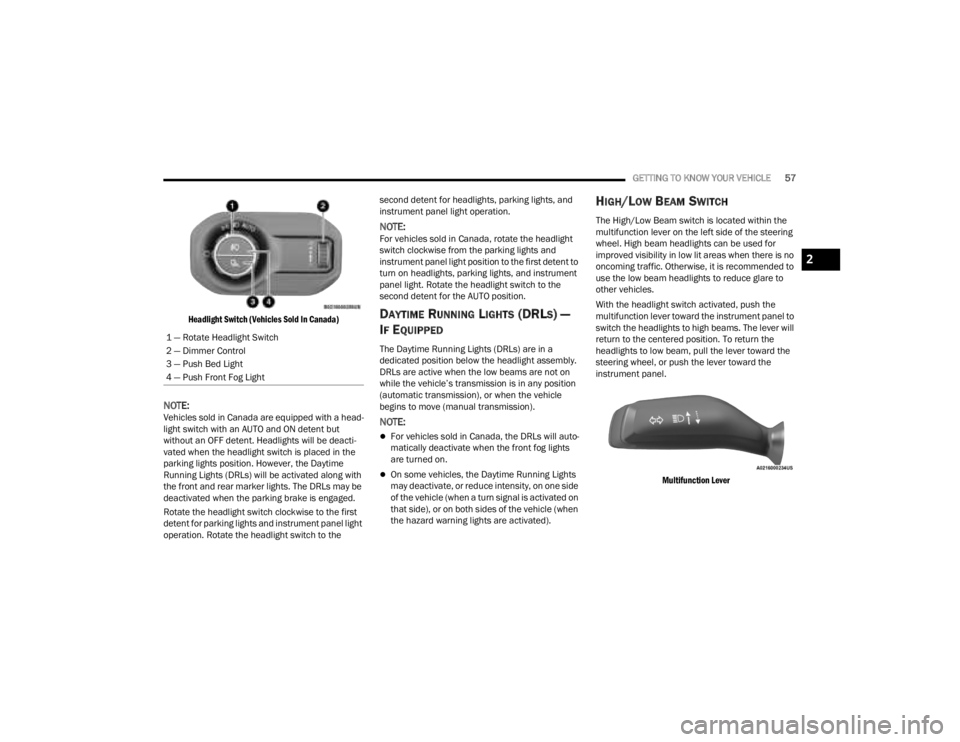
NOTE:Vehicles sold in Canada are equipped with a head -
light switch with an AUTO and ON detent but
without an OFF detent. Headlights will be deacti -
vated when the headlight switch is placed in the
parking lights position. However, the Daytime
Running Lights (DRLs) will be activated along with
the front and rear marker lights. The DRLs may be
deactivated when the parking brake is engaged.
Rotate the headlight switch clockwise to the first
detent for parking lights and instrument panel light
operation. Rotate the headlight switch to the second detent for headlights, parking lights, and
instrument panel light operation.
NOTE:For vehicles sold in Canada, rotate the headlight
switch clockwise from the parking lights and
instrument panel light position to the first detent to
turn on headlights, parking lights, and instrument
panel light. Rotate the headlight switch to the
second detent for the AUTO position.
DAYTIME RUNNING LIGHTS (DRLS) —
I
F EQUIPPED
The Daytime Running Lights (DRLs) are in a
dedicated position below the headlight assembly.
DRLs are active when the low beams are not on
while the vehicle’s transmission is in any position
(automatic transmission), or when the vehicle
begins to move (manual transmission).
NOTE:
For vehicles sold in Canada, the DRLs will auto -
matically deactivate when the front fog lights
are turned on.
On some vehicles, the Daytime Running Lights
may deactivate, or reduce intensity, on one side
of the vehicle (when a turn signal is activated on
that side), or on both sides of the vehicle (when
the hazard warning lights are activated).
HIGH/LOW BEAM SWITCH
The High/Low Beam switch is located within the
multifunction lever on the left side of the steering
wheel. High beam headlights can be used for
improved visibility in low lit areas when there is no
oncoming traffic. Otherwise, it is recommended to
use the low beam headlights to reduce glare to
other vehicles.
With the headlight switch activated, push the
multifunction lever toward the instrument panel to
switch the headlights to high beams. The lever will
return to the centered position. To return the
headlights to low beam, pull the lever toward the
steering wheel, or push the lever toward the
instrument panel.
Multifunction Lever
1 — Rotate Headlight Switch
2 — Dimmer Control
3 — Push Bed Light
4 — Push Front Fog Light
2
23_JT_OM_EN_USC_t.book Page 57
Page 60 of 448
58GETTING TO KNOW YOUR VEHICLE
AUTOMATIC HIGH BEAM HEADLAMP
C
ONTROL — IF EQUIPPED
The Automatic High Beam Headlamp Control
system provides increased forward lighting at night
by automatically controlling the high beams
through the use of a camera mounted on the
vehicle’s header. This camera detects vehicle
specific light and automatically switches from high
beams to low beams until the approaching vehicle
is out of view.
NOTE:
The Automatic High Beam Headlamp Control
can be turned on or off by selecting “ON” under
“Auto Dim High Beams” within your Uconnect
Settings Ú page 215, as well as turning the
headlight switch to the AUTO position and
placing the multifunction lever in the high beam
position.
Broken, muddy, or obstructed headlights and
taillights of vehicles in the field of view will
cause headlights to remain on longer (closer to
the vehicle). Also, dirt, film, and other obstruc -
tions on the windshield or camera lens will
cause the system to function improperly.
FLASH-TO-PASS
The Flash-To-Pass feature will illuminate the high
beam headlights temporarily to signal another
vehicle of a passing occurrence. Pull and hold the
Multifunction Lever to activate the Flash-To-Pass
feature. When the lever is released, the
Flash-To-Pass feature will deactivate.
AUTOMATIC HEADLIGHTS — IF EQUIPPED
The Automatic Headlight System will turn the
headlights on or off according to ambient light
levels. To turn the system on, rotate the headlight
switch clockwise to the last detent for automatic
headlight operation. When the system is on, the
headlight time delay feature is also on. This means
the headlights will stay on for up to 90 seconds
(programmable through the Uconnect Settings
Ú
page 215) after you place the ignition into the
OFF position. To turn the automatic system off,
move the headlight switch out of the AUTO position.
NOTE:The engine must be running before the headlights
will come on in the automatic mode.
LIGHTS-ON REMINDER
If the headlights or parking lights are left on after
the ignition is placed in the OFF position, the vehicle
will chime when the driver’s door is opened.
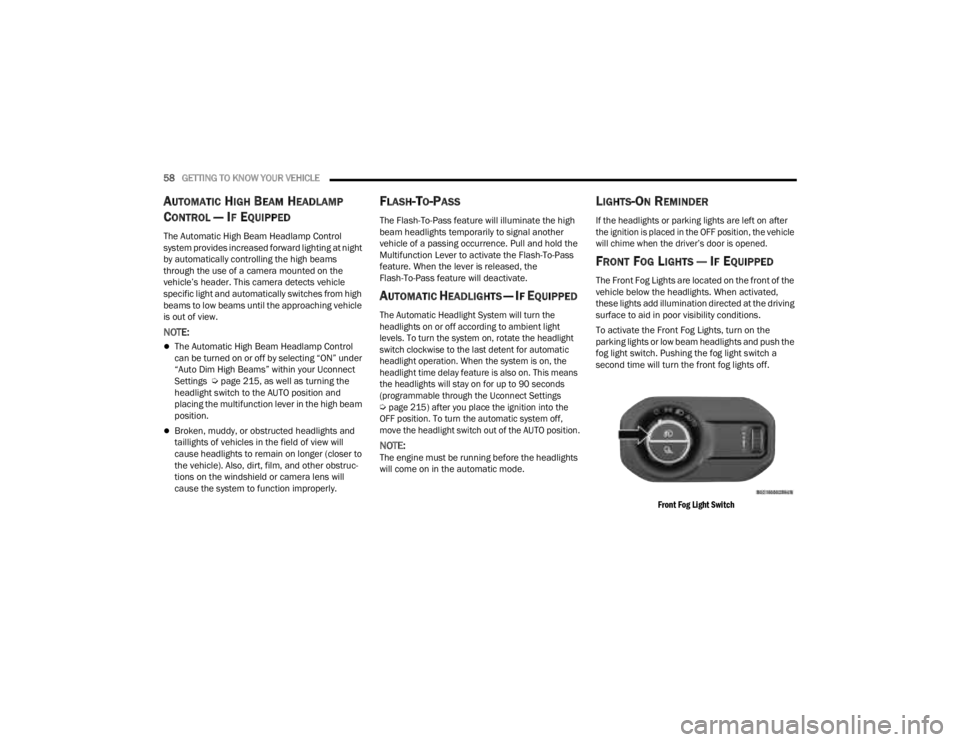
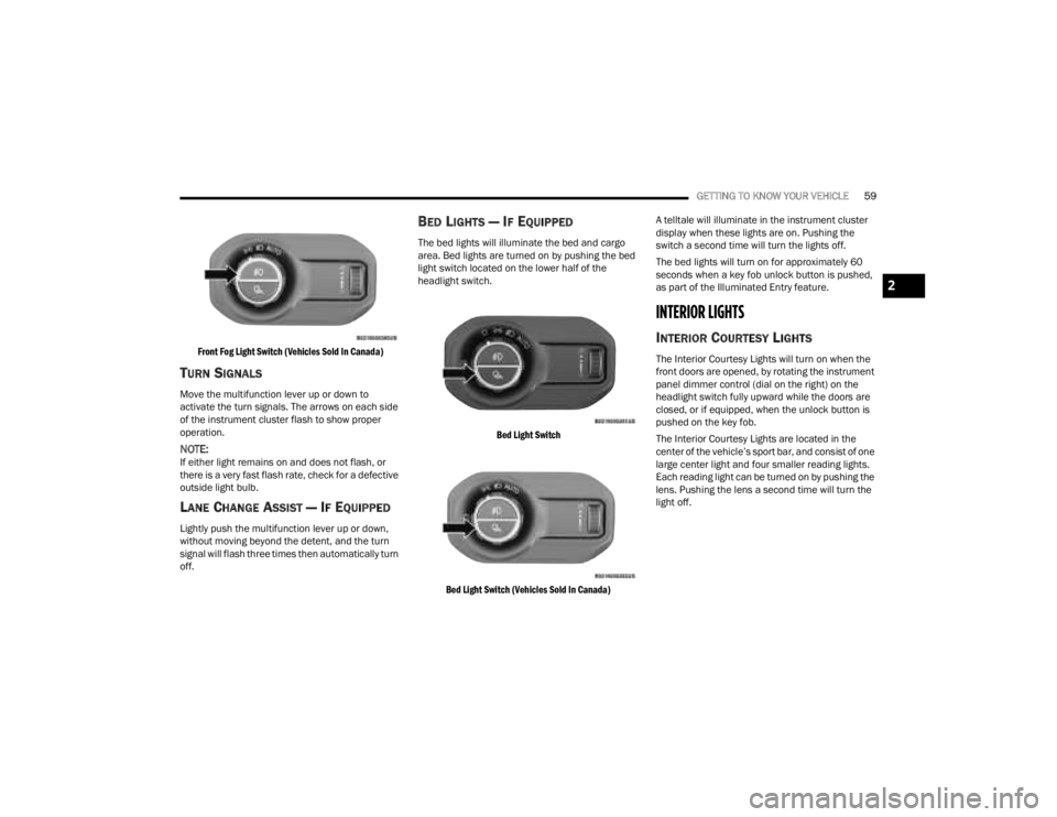
FRONT FOG LIGHTS — IF EQUIPPED
The Front Fog Lights are located on the front of the
vehicle below the headlights. When activated,
these lights add illumination directed at the driving
surface to aid in poor visibility conditions.
To activate the Front Fog Lights, turn on the
parking lights or low beam headlights and push the
fog light switch. Pushing the fog light switch a
second time will turn the front fog lights off.
Front Fog Light Switch
23_JT_OM_EN_USC_t.book Page 58
Page 61 of 448
GETTING TO KNOW YOUR VEHICLE59
Front Fog Light Switch (Vehicles Sold In Canada)
TURN SIGNALS
Move the multifunction lever up or down to
activate the turn signals. The arrows on each side
of the instrument cluster flash to show proper
operation.
NOTE:If either light remains on and does not flash, or
there is a very fast flash rate, check for a defective
outside light bulb.
LANE CHANGE ASSIST — IF EQUIPPED
Lightly push the multifunction lever up or down,
without moving beyond the detent, and the turn
signal will flash three times then automatically turn
off.
BED LIGHTS — IF EQUIPPED
The bed lights will illuminate the bed and cargo
area. Bed lights are turned on by pushing the bed
light switch located on the lower half of the
headlight switch.
Bed Light Switch
Bed Light Switch (Vehicles Sold In Canada)
A telltale will illuminate in the instrument cluster
display when these lights are on. Pushing the
switch a second time will turn the lights off.
The bed lights will turn on for approximately 60
seconds when a key fob unlock button is pushed,
as part of the Illuminated Entry feature.
INTERIOR LIGHTS
INTERIOR COURTESY LIGHTS
The Interior Courtesy Lights will turn on when the
front doors are opened, by rotating the instrument
panel dimmer control (dial on the right) on the
headlight switch fully upward while the doors are
closed, or if equipped, when the unlock button is
pushed on the key fob.
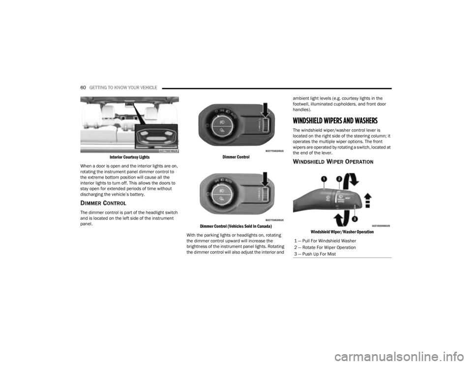
The Interior Courtesy Lights are located in the
center of the vehicle’s sport bar, and consist of one
large center light and four smaller reading lights.
Each reading light can be turned on by pushing the
lens. Pushing the lens a second time will turn the
light off.
2
23_JT_OM_EN_USC_t.book Page 59
Page 62 of 448
60GETTING TO KNOW YOUR VEHICLE
Interior Courtesy Lights
When a door is open and the interior lights are on,
rotating the instrument panel dimmer control to
the extreme bottom position will cause all the
interior lights to turn off. This allows the doors to
stay open for extended periods of time without
discharging the vehicle’s battery.
DIMMER CONTROL
The dimmer control is part of the headlight switch
and is located on the left side of the instrument
panel.
Dimmer Control
Dimmer Control (Vehicles Sold In Canada)
With the parking lights or headlights on, rotating
the dimmer control upward will increase the
brightness of the instrument panel lights. Rotating
the dimmer control will also adjust the interior and ambient light levels (e.g. courtesy lights in the
footwell, illuminated cupholders, and front door
handles).
WINDSHIELD WIPERS AND WASHERS
The windshield wiper/washer control lever is
located on the right side of the steering column; it
operates the multiple wiper options. The front
wipers are operated by rotating a switch, located at
the end of the lever.
WINDSHIELD WIPER OPERATION
Windshield Wiper/Washer Operation
1 — Pull For Windshield Washer
2 — Rotate For Wiper Operation
3 — Push Up For Mist
23_JT_OM_EN_USC_t.book Page 60
Page 66 of 448
64GETTING TO KNOW YOUR VEHICLE
Blower Control
Blower Control regulates the amount of
air forced through the Climate Control
system. There are seven blower speeds
available. Adjusting the blower will cause
automatic mode to switch to manual operation.
The speeds can be selected using either the
blower control knob on the faceplate or the
buttons on the touchscreen.
Faceplate
The blower speed increases as you turn the blower
control knob clockwise from the lowest blower
setting. The blower speed decreases as you turn
the blower control knob counterclockwise.
Touchscreen
Use the small blower icon to reduce the blower
setting and the large blower icon to increase the
blower setting. Blower can also be selected by
pressing the blower bar area between the icons.
Mode Control
Turn the mode control knob or press one
of the Mode buttons on the touchscreen
to adjust airflow distribution. The airflow
distribution mode can be adjusted so air
comes from the instrument panel outlets, floor
outlets, defrost outlets and demist outlets.
Panel Mode
Air comes from the outlets in the
instrument panel. Each of these outlets
can be individually adjusted to direct the
flow of air. The air vanes of the center
outlets and outboard outlets can be moved up and
down or side to side to regulate airflow direction.
There is a shut-off wheel located below the air
vanes to shut off or adjust the amount of airflow
from these outlets.
Bi-Level Mode
Air comes from the instrument panel
outlets and floor outlets. A slight amount
of air is directed through the defrost and
side window demister outlets.
NOTE:Bi-Level mode is designed under comfort condi -
tions to provide cooler air out of the panel outlets
and warmer air from the floor outlets.
Floor Mode
Air comes from the floor outlets. A slight
amount of air is directed through the
defrost and side window demister
outlets.
Mix Mode
Air is directed through the floor, defrost,
and side window demister outlets. This
setting works best in cold or snowy
conditions that require extra heat to the
windshield. This setting is good for maintaining
comfort while reducing moisture on the
windshield.
Climate Control OFF Button
Press and release this button on the
touchscreen, or push and release the
button on the blower knob to turn the
Climate Control ON/OFF.
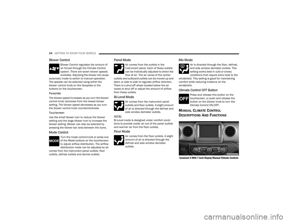
MANUAL CLIMATE CONTROL
D
ESCRIPTIONS AND FUNCTIONS
Uconnect 4 With 7-inch Display Manual Climate Controls
23_JT_OM_EN_USC_t.book Page 64
Page 68 of 448
66GETTING TO KNOW YOUR VEHICLE
Temperature Control
Temperature Control regulates the
temperature of the air forced through the
climate system. The temperature
increases as you turn the temperature
control knob clockwise.
The temperature decreases as you turn
the temperature control knob
counterclockwise. Heater Only
Turning the temperature control knob clockwise
increases the heating temperature and turning the
temperature control knob counterclockwise
decreases the heating temperature.
Blower Control
Blower Control regulates the amount of
air forced through the climate system.
There are seven blower speeds available.
The blower speeds increase as you turn
the blower control knob clockwise from the lowest
blower setting. The blower speed decreases as you
turn the blower control knob counterclockwise.
Mode Control
Turn the mode control knob or press one
of the Mode buttons on the touchscreen
to adjust airflow distribution. The airflow
distribution mode can be adjusted so air
comes from the instrument panel outlets, floor
outlets, defrost outlets and demist outlets.
Panel Mode
Air comes from the outlets in the
instrument panel. Each of these outlets
can be individually adjusted to direct the
flow of air. The air vanes of the center
outlets and outboard outlets can be moved up and
down or side to side to regulate airflow direction.
There is a shut-off wheel located below the air vanes to shut off or adjust the amount of airflow
from these outlets.
Bi-Level Mode
Air comes from the instrument panel
outlets and floor outlets. A slight amount
of air is directed through the defrost and
side window demister outlets.
NOTE:Bi-Level mode is designed under comfort condi
-
tions to provide cooler air out of the panel outlets
and warmer air from the floor outlets.
Floor Mode
Air comes from the floor outlets. A slight
amount of air is directed through the
defrost and side window demister outlets.
Mix Mode
Air is directed through the floor, defrost,
and side window demister outlets. This
setting works best in cold or snowy
conditions that require extra heat to the
windshield. This setting is good for maintaining
comfort while reducing moisture on the
windshield.
Climate Control OFF Button
Press and release this button to turn the
Climate Control ON/OFF.
CAUTION!
Failure to follow these cautions can cause
damage to the heating elements:
Use care when washing the inside of the rear
window. Do not use abrasive window cleaners
on the interior surface of the window. Use a
soft cloth and a mild washing solution, wiping
parallel to the heating elements. Labels can
be peeled off after soaking with warm water.
Do not use scrapers, sharp instruments, or
abrasive window cleaners on the interior
surface of the window.
Keep all objects a safe distance from the
window.
23_JT_OM_EN_USC_t.book Page 66