light JEEP GLADIATOR 2023 User Guide
[x] Cancel search | Manufacturer: JEEP, Model Year: 2023, Model line: GLADIATOR, Model: JEEP GLADIATOR 2023Pages: 448, PDF Size: 17.37 MB
Page 22 of 448
20GETTING TO KNOW YOUR VEHICLE
NOTE:When opening the driver's door with the ignition in
the ON/RUN (engine not running) position, a chime
will sound to remind you to place the ignition in the
OFF position. In addition to the chime, the
message will display “Ignition Or Accessory On” in
the cluster.
REMOTE START — IF EQUIPPED
(GASOLINE)
This system uses the key fob to start the
engine conveniently from outside the
vehicle while still maintaining security.
The system has a range of 328 ft (100 m).
Remote Start is used to defrost windows in cold
weather, and to reach a comfortable climate in all
ambient conditions before the driver enters the
vehicle.
NOTE:
The vehicle must be equipped with an auto -
matic transmission to be equipped with Remote
Start.
Obstructions between the vehicle and key fob
may reduce this range Ú page 432.
HOW TO USE REMOTE START
Push and release the Remote Start button on the
key fob twice within five seconds. The vehicle
doors and tailgate will lock, the turn signals will
flash twice, and the horn will chirp twice (if
equipped). Pushing the Remote Start button again
will shut the engine off.
NOTE:
With Remote Start, the engine will only run for
15 minutes.
Remote Start can only be used twice.
If an engine fault is present or fuel level is low,
the vehicle will start and then shut down in
10 seconds.
The parking lights will turn on and remain on
during Remote Start mode.
For security, power window operation is
disabled when the vehicle is in the Remote Start
mode.
The ignition must be placed in the ON/RUN posi -
tion before the Remote Start sequence can be
repeated for a third cycle.
All of the following conditions must be met before
the engine will remote start:
Gear selector in PARK
Doors closed
Hood closed
Hazard switch off
Brake switch inactive (brake pedal not pressed)
Battery at an acceptable charge level
Panic button not pushed
System not disabled from previous Remote
Start event
CAUTION!
An unlocked vehicle is an invitation for thieves.
Always remove key fob from the vehicle and lock
all doors when leaving the vehicle unattended.
WARNING!
Do not start or run an engine in a closed
garage or confined area. Exhaust gas contains
carbon monoxide (CO) which is odorless and
colorless. Carbon monoxide is poisonous and
can cause serious injury or death when
inhaled.
Keep key fobs away from children. Operation
of the Remote Start system, windows, door
locks or other controls could cause serious
injury or death.
23_JT_OM_EN_USC_t.book Page 20
Page 23 of 448

GETTING TO KNOW YOUR VEHICLE21
Vehicle Security system indicator flashing
Ignition in OFF position
Fuel level meets minimum requirement
All removable doors must not be removed
Malfunction Indicator Light not illuminated
TO EXIT REMOTE START MODE
To drive the vehicle after starting the Remote Start
system, either push and release the unlock button
on the key fob to unlock the doors, or unlock the
vehicle using Keyless Enter ‘n Go™ — Passive Entry
via the door handles, and disarm the Vehicle
Security system (if equipped). Then, prior to the
end of the 15 minute cycle, push and release the
START/STOP ignition button.
The Remote Start system will turn the engine off if
the Remote Start button on the key fob is pushed
again, or if the engine is allowed to run for the
entire 15 minute cycle. Once the ignition is placed
in the ON/RUN position, the climate controls will
resume previously set operations (temperature,
blower control, etc.).
NOTE:
To avoid unintentional shutdowns, the system
will disable for two seconds after receiving a
valid Remote Start request.
For vehicles equipped with the Keyless
Enter ‘n Go™ — Passive Entry feature, the message “Remote Start Active — Push Start
Button” will display in the instrument cluster
display until you push the START/STOP ignition
button.
REMOTE START FRONT DEFROST
A
CTIVATION — IF EQUIPPED
When Remote Start is active, and the outside
ambient temperature is 40°F (4.5°C) or below, the
system will automatically activate front defrost for
15 minutes or less. The time is dependent on the
ambient temperature. Once the timer expires, the
system will automatically adjust the settings
depending on ambient conditions. See “Remote
Start Comfort Systems — If Equipped” in the next
section for detailed operation.
REMOTE START COMFORT SYSTEMS —
I
F EQUIPPED
When Remote Start is activated, the front and rear
defrost will automatically turn on in cold weather.
The heated steering wheel and driver heated seat
feature will also turn on if programmed in the
Comfort menu screen within Uconnect Settings
Ú page 215.
Automatic Temperature Control (ATC) —
If Equipped
The climate controls automatically adjust to an
optimal temperature and mode, dependent upon
the outside ambient temperature. When the
ignition is placed in the ON/RUN position, the
climate controls will resume their previous
settings.
Manual Temperature Control (MTC) — If Equipped
In ambient temperatures of 40°F (4.5°C) or
below, the climate settings will default to
maximum heat, with fresh air entering the
cabin. If the front defrost timer expires, the
vehicle will enter Mix Mode.
In ambient temperatures from 40°F (4.5°C) to
78°F (26°C), the climate settings will be based
on the last settings selected by the driver.
In ambient temperatures of 78°F (26°C) or
above, the climate settings will default to MAX
A/C, Bi-Level mode, and Recirculation on.
WARNING!
Do not start or run an engine in a closed
garage or confined area. Exhaust gas contains
carbon monoxide (CO) which is odorless and
colorless. Carbon monoxide is poisonous and
can cause serious injury or death when
inhaled.
Keep key fobs away from children. Operation
of the Remote Start system, windows, door
locks or other controls could cause serious
injury or death.
2
23_JT_OM_EN_USC_t.book Page 21
Page 25 of 448

GETTING TO KNOW YOUR VEHICLE23
The parking lights will turn on and remain on
during Remote Start mode.
For security, power window operation is
disabled when the vehicle is in the Remote Start
mode.
The ignition must be placed in the ON/RUN posi -
tion before the Remote Start sequence can be
repeated for a third cycle.
All of the following conditions must be met before
the engine will remote start:
Gear selector in PARK
Doors closed
Hood closed
Hazard switch off
Brake switch inactive (brake pedal not pressed)
Battery at an acceptable charge level
Panic button not pushed
Fuel meets minimum requirement
System not disabled from previous Remote
Start event
Vehicle Security system not active
All removable doors must not be removed
Malfunction Indicator/Check Engine telltale is
not illuminated
Water In Fuel telltale is not illuminated
Wait To Start telltale is not illuminated
For additional Remote Start information, see
Ú page 21.
VEHICLE SECURITY SYSTEM — IF EQUIPPED
The Vehicle Security system monitors the vehicle
doors for unauthorized entry and the ignition
switch for unauthorized operation. When the
system is activated, the interior switches for door
locks are disabled. The Vehicle Security system
provides both audible and visible signals. If
something triggers the alarm, the Vehicle Security
system will provide the following audible and
visible signals: the horn will pulse, the parking
lights and/or turn signals will flash, and the Vehicle
Security Light in the instrument cluster will flash.
TO ARM THE SYSTEM
Follow these steps to arm the Vehicle Security
system:
1. Make sure the vehicle’s ignition is placed in
the OFF position.
2. Perform one of the following methods to lock the vehicle:
Push the lock button on the interior power
door lock switch with the driver and/or
passenger door open.
Push the lock button on the exterior Passive
Entry door handle with a valid key fob avail -
able in the same exterior zone Ú page 25.
Push the lock button on the key fob.
3. If any doors are open, close them.
NOTE:The Vehicle Security system will not arm if you lock
the doors using the manual door lock.
TO DISARM THE SYSTEM
The Vehicle Security system can be disarmed using
any of the following methods:
Push the unlock button on the key fob.
Grab the Passive Entry door handle (if equipped)
Ú page 25.
Cycle the vehicle ignition system out of the OFF
position.
NOTE:
The driver's door key cylinder cannot arm or
disarm the Vehicle Security system.
When the Vehicle Security system is armed, the
interior power door lock switches will not unlock
the doors.
The Vehicle Security system is designed to protect
your vehicle. However, you can create conditions
where the system will give you a false alarm. If one
of the previously described arming sequences has
2
23_JT_OM_EN_USC_t.book Page 23
Page 26 of 448
24GETTING TO KNOW YOUR VEHICLE
occurred, the Vehicle Security system will arm
regardless of whether you are in the vehicle or not.
If you remain in the vehicle and open a door, the
alarm will sound. If this occurs, disarm the Vehicle
Security system.
If the Vehicle Security system is armed and the
battery becomes disconnected, the Vehicle
Security system will remain armed when the
battery is reconnected; the exterior lights will flash,
and the horn will sound. If this occurs, disarm the
Vehicle Security system.
REARMING OF THE SYSTEM
If something triggers the alarm and no action is
taken to disarm it, the Vehicle Security system will
turn the horn off after a 29 second cycle (with five
seconds between cycles and up to eight cycles if
the trigger remains active) and then rearm itself.
DOORS
MANUAL DOOR LOCKS
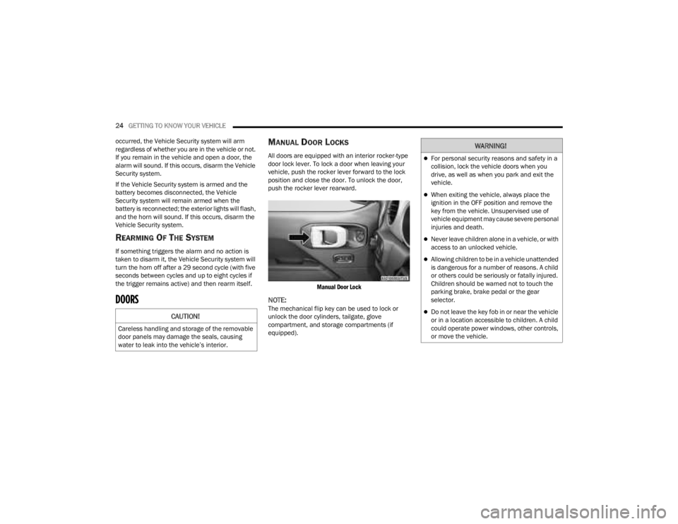
All doors are equipped with an interior rocker-type
door lock lever. To lock a door when leaving your
vehicle, push the rocker lever forward to the lock
position and close the door. To unlock the door,
push the rocker lever rearward.
Manual Door Lock
NOTE:The mechanical flip key can be used to lock or
unlock the door cylinders, tailgate, glove
compartment, and storage compartments (if
equipped).CAUTION!
Careless handling and storage of the removable
door panels may damage the seals, causing
water to leak into the vehicle’s interior.
WARNING!
For personal security reasons and safety in a
collision, lock the vehicle doors when you
drive, as well as when you park and exit the
vehicle.
When exiting the vehicle, always place the
ignition in the OFF position and remove the
key from the vehicle. Unsupervised use of
vehicle equipment may cause severe personal
injuries and death.
Never leave children alone in a vehicle, or with
access to an unlocked vehicle.
Allowing children to be in a vehicle unattended
is dangerous for a number of reasons. A child
or others could be seriously or fatally injured.
Children should be warned not to touch the
parking brake, brake pedal or the gear
selector.
Do not leave the key fob in or near the vehicle
or in a location accessible to children. A child
could operate power windows, other controls,
or move the vehicle.
23_JT_OM_EN_USC_t.book Page 24
Page 27 of 448
GETTING TO KNOW YOUR VEHICLE25
(Continued)
POWER DOOR LOCKS — IF EQUIPPED
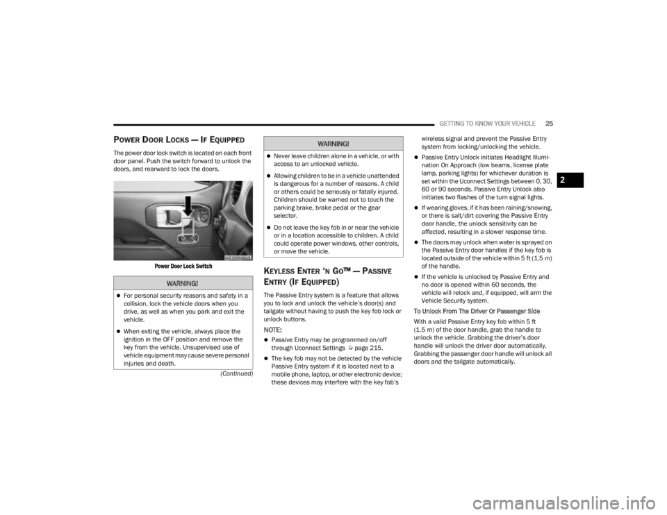
The power door lock switch is located on each front
door panel. Push the switch forward to unlock the
doors, and rearward to lock the doors.
Power Door Lock Switch
KEYLESS ENTER ‘N GO™ — PASSIVE
E
NTRY (IF EQUIPPED)
The Passive Entry system is a feature that allows
you to lock and unlock the vehicle’s door(s) and
tailgate without having to push the key fob lock or
unlock buttons.
NOTE:
Passive Entry may be programmed on/off
through Uconnect Settings Ú page 215.
The key fob may not be detected by the vehicle
Passive Entry system if it is located next to a
mobile phone, laptop, or other electronic device;
these devices may interfere with the key fob’s wireless signal and prevent the Passive Entry
system from locking/unlocking the vehicle.
Passive Entry Unlock initiates Headlight Illumi
-
nation On Approach (low beams, license plate
lamp, parking lights) for whichever duration is
set within the Uconnect Settings between 0, 30,
60 or 90 seconds. Passive Entry Unlock also
initiates two flashes of the turn signal lights.
If wearing gloves, if it has been raining/snowing,
or there is salt/dirt covering the Passive Entry
door handle, the unlock sensitivity can be
affected, resulting in a slower response time.
The doors may unlock when water is sprayed on
the Passive Entry door handles if the key fob is
located outside of the vehicle within 5 ft (1.5 m)
of the handle.
If the vehicle is unlocked by Passive Entry and
no door is opened within 60 seconds, the
vehicle will relock and, if equipped, will arm the
Vehicle Security system.
To Unlock From The Driver Or Passenger Side
With a valid Passive Entry key fob within 5 ft
(1.5 m) of the door handle, grab the handle to
unlock the vehicle. Grabbing the driver’s door
handle will unlock the driver door automatically.
Grabbing the passenger door handle will unlock all
doors and the tailgate automatically.WARNING!
For personal security reasons and safety in a
collision, lock the vehicle doors when you
drive, as well as when you park and exit the
vehicle.
When exiting the vehicle, always place the
ignition in the OFF position and remove the
key from the vehicle. Unsupervised use of
vehicle equipment may cause severe personal
injuries and death.
Never leave children alone in a vehicle, or with
access to an unlocked vehicle.
Allowing children to be in a vehicle unattended
is dangerous for a number of reasons. A child
or others could be seriously or fatally injured.
Children should be warned not to touch the
parking brake, brake pedal or the gear
selector.
Do not leave the key fob in or near the vehicle
or in a location accessible to children. A child
could operate power windows, other controls,
or move the vehicle.
WARNING!
2
23_JT_OM_EN_USC_t.book Page 25
Page 33 of 448
GETTING TO KNOW YOUR VEHICLE31
Replacing The Wiring Connector Into The Wiring
Harness
To reinstall the wiring connector on the vehicle’s
door into the harness just inside the vehicle,
proceed as follows:
NOTE:Make sure there is plenty of slack on the wiring
connector during installation. Close the door
slightly to provide more slack if needed.
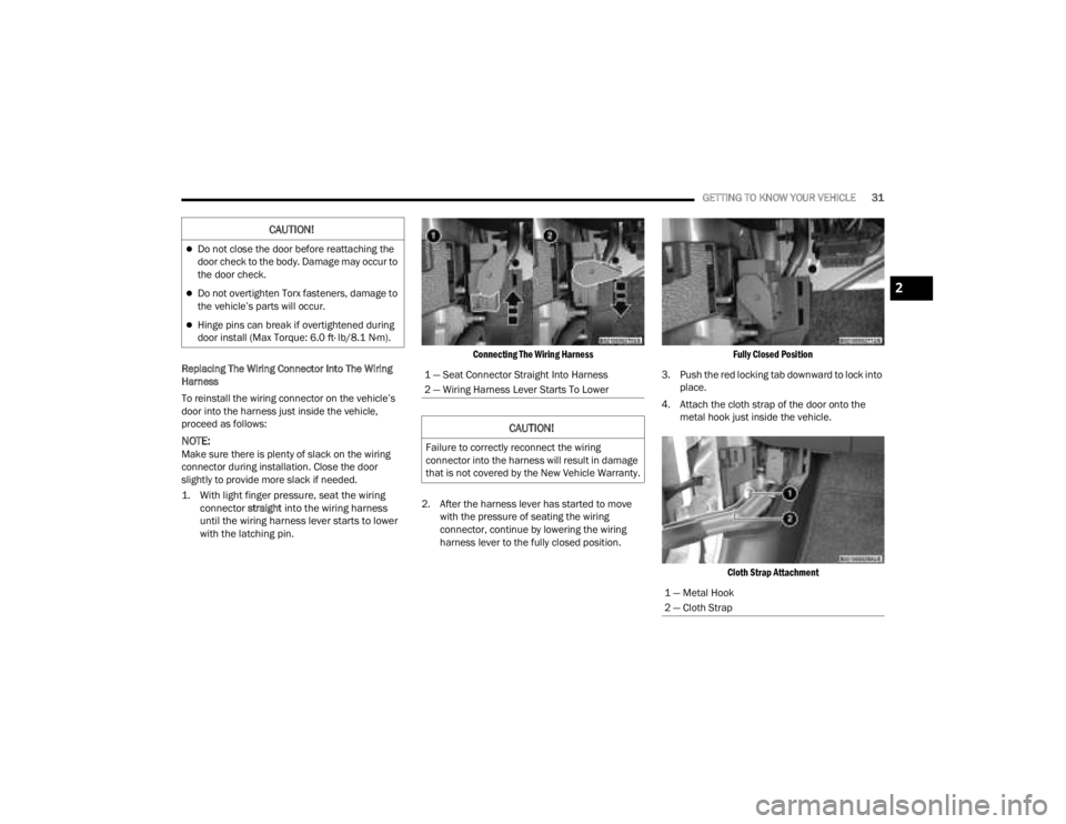
1. With light finger pressure, seat the wiring connector
straight
into the wiring harness
until the wiring harness lever starts to lower
with the latching pin.
Connecting The Wiring Harness
2. After the harness lever has started to move with the pressure of seating the wiring
connector, continue by lowering the wiring
harness lever to the fully closed position.
Fully Closed Position
3. Push the red locking tab downward to lock into place.
4. Attach the cloth strap of the door onto the metal hook just inside the vehicle.
Cloth Strap Attachment
CAUTION!
Do not close the door before reattaching the
door check to the body. Damage may occur to
the door check.
Do not overtighten Torx fasteners, damage to
the vehicle’s parts will occur.
Hinge pins can break if overtightened during
door install (Max Torque: 6.0 ft· lb/8.1 N·m).
1 — Seat Connector Straight Into Harness
2 — Wiring Harness Lever Starts To Lower
CAUTION!
Failure to correctly reconnect the wiring
connector into the harness will result in damage
that is not covered by the New Vehicle Warranty.
1 — Metal Hook
2 — Cloth Strap
2
23_JT_OM_EN_USC_t.book Page 31
Page 41 of 448
GETTING TO KNOW YOUR VEHICLE39
2. With the bolts loose, the door can be moved forward by pushing the door handle toward the
front of the vehicle, and/or upward by grabbing
the door handle and lifting towards the roof.
3. Once the gaps between the door and vehicle body are uniform around the entire door,
tighten the door hinge bolts to 20.3 ft· lb /
27.5 N·m (Max Torque: 27.3 ft· lb / 37 N·m).
Upper Door Adjustment
After installation of the half-doors, if water leaks or
wind noise is observed, the seal of the upper
half-door to the door opening may need to be
adjusted.
To determine if the upper half-door needs to be
adjusted, proceed as follows:
1. Determine which door is affected.
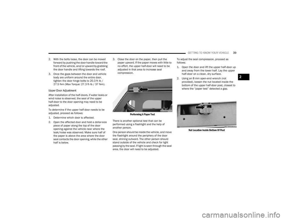
2. Open the affected door and hold a dollar-size piece of paper along the top of the door
opening against the vehicle near where the
leak/noise was observed. Make sure half of
the paper is above the area where the door
seal contacts the door opening, while the other
half is below. 3. Close the door on the paper, then pull the
paper upward. If the paper moves with little to
no effort, the upper half-door will need to be
adjusted in that area to increase seal
compression.
Performing A Paper Test
There is another optional test that can be
performed using a flashlight and the help of
another person.
One person should be inside the vehicle, and move
the flashlight around the periphery of the door
seal, shining outward. The other person should
stand outside of the vehicle and check for light
passing by the seal. If light is seen through the seal
area, the door will need to be adjusted. To adjust the seal compression, proceed as
follows:
1. Open the door and lift the upper half-door up
and away from the lower half. Lay the upper
half-door on a clean, dry surface.
2. Using an 8 mm open-end wrench (not provided), loosen the nut located inside the
bottom of the upper half-door post, closest to
where the “paper test” detected a gap.
Nut Location Inside Bottom Of Post
2
23_JT_OM_EN_USC_t.book Page 39
Page 52 of 448
50GETTING TO KNOW YOUR VEHICLE
Uconnect 4C/4C NAV with 8.4-inch Display
If you see the NAV icon on the bottom bar or in the
Apps menus of your 8.4-inch touchscreen, you
have the Uconnect 4C NAV system. If not, you have
a Uconnect 4C with 8.4-inch display system.
BASIC VOICE COMMANDS
The following basic Voice Commands can be given
at any point while using your Uconnect system.
Push the VR button . After the beep, say:
“ Cancel ” to stop a current voice session.
“Help ” to hear a list of suggested Voice
Commands.
“ Repeat ” to listen to the system prompts again.
Notice the visual cues that inform you of your Voice
Recognition system’s status.
GET STARTED
The VR button is used to activate/deactivate
your Voice Recognition system.
Helpful hints for using Voice Recognition:
Reduce background noise. Wind noise and
passenger conversations are examples of noise
that may impact recognition.
Speak clearly at a normal pace and volume
while facing straight ahead.
Each time you give a Voice Command, first push
the VR button, wait until after the beep, then say
your Voice Command.
You can interrupt the help message or system
prompts by pushing the VR button and saying a
Voice Command from the current category.
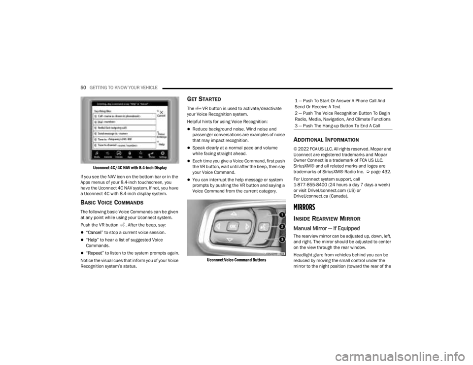
Uconnect Voice Command Buttons
ADDITIONAL INFORMATION
© 2022 FCA US LLC. All rights reserved. Mopar and
Uconnect are registered trademarks and Mopar
Owner Connect is a trademark of FCA US LLC.
SiriusXM® and all related marks and logos are
trademarks of SiriusXM® Radio Inc. Ú page 432.
For Uconnect system support, call
1-877-855-8400 (24 hours a day 7 days a week)
or visit DriveUconnect.com (US) or
DriveUconnect.ca (Canada).
MIRRORS
INSIDE REARVIEW MIRROR
Manual Mirror — If Equipped
The rearview mirror can be adjusted up, down, left,
and right. The mirror should be adjusted to center
on the view through the rear window.
Headlight glare from vehicles behind you can be
reduced by moving the small control under the
mirror to the night position (toward the rear of the
1 — Push To Start Or Answer A Phone Call And
Send Or Receive A Text
2 — Push The Voice Recognition Button To Begin
Radio, Media, Navigation, And Climate Functions
3 — Push The Hang-up Button To End A Call
23_JT_OM_EN_USC_t.book Page 50
Page 53 of 448
GETTING TO KNOW YOUR VEHICLE51
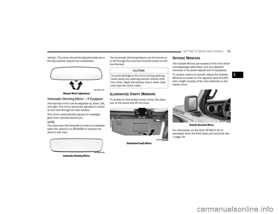
vehicle). The mirror should be adjusted while set in
the day position (toward the windshield).
Manual Mirror Adjustment
Automatic Dimming Mirror — If Equipped
The rearview mirror can be adjusted up, down, left,
and right. The mirror should be adjusted to center
on the view through the rear window.
This mirror automatically adjusts for headlight
glare from vehicles behind you.
NOTE:The Automatic Dimming Mirror feature is disabled
when the vehicle is in REVERSE to improve the
driver’s rear view.
Automatic Dimming Mirror
The Automatic Dimming feature can be turned on
or off through the Uconnect Controls button on the
touchscreen.
ILLUMINATED VANITY MIRRORS
To access an illuminated vanity mirror, flip down
one of the visors and lift the cover.
Illuminated Vanity Mirror
OUTSIDE MIRRORS
The Outside Mirrors are located on the front driver
and passenger side doors, and are adjusted
manually or by power adjustment (if equipped).
To receive maximum benefit, adjust the Outside
Mirror(s) to center on the adjacent lane of traffic
with a slight overlap of the view obtained on the
inside mirror.
Outside Rearview Mirror
For information on the Door Off Mirror Kit (if
equipped) when the front doors are removed, see
Ú page 34.
CAUTION!
To avoid damage to the mirror during cleaning,
never spray any cleaning solution directly onto
the mirror. Apply the solution onto a clean cloth
and wipe the mirror clean.2
23_JT_OM_EN_USC_t.book Page 51
Page 54 of 448
52GETTING TO KNOW YOUR VEHICLE
POWER MIRRORS — IF EQUIPPED
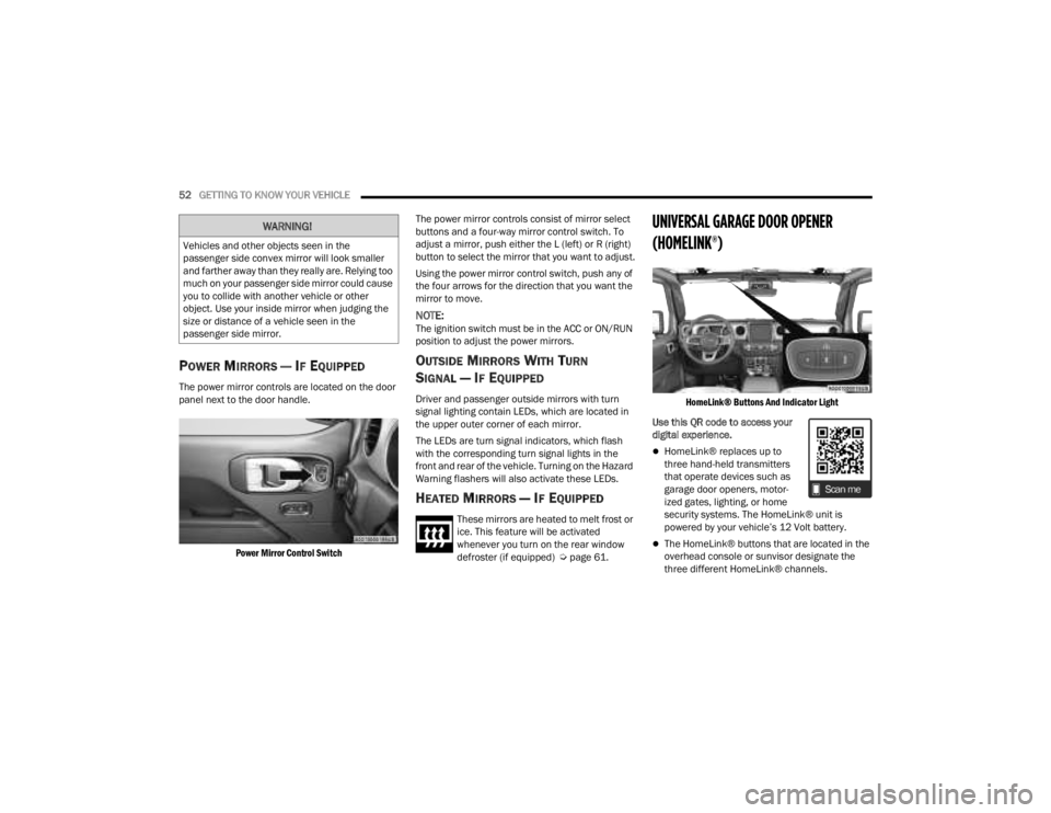
The power mirror controls are located on the door
panel next to the door handle.
Power Mirror Control Switch
The power mirror controls consist of mirror select
buttons and a four-way mirror control switch. To
adjust a mirror, push either the L (left) or R (right)
button to select the mirror that you want to adjust.
Using the power mirror control switch, push any of
the four arrows for the direction that you want the
mirror to move.
NOTE:The ignition switch must be in the ACC or ON/RUN
position to adjust the power mirrors.
OUTSIDE MIRRORS WITH TURN
SIGNAL — IF EQUIPPED
Driver and passenger outside mirrors with turn
signal lighting contain LEDs, which are located in
the upper outer corner of each mirror.
The LEDs are turn signal indicators, which flash
with the corresponding turn signal lights in the
front and rear of the vehicle. Turning on the Hazard
Warning flashers will also activate these LEDs.
HEATED MIRRORS — IF EQUIPPED
These mirrors are heated to melt frost or
ice. This feature will be activated
whenever you turn on the rear window
defroster (if equipped) Ú
page 61.
UNIVERSAL GARAGE DOOR OPENER
(HOMELINK®)
HomeLink® Buttons And Indicator Light
Use this QR code to access your
digital experience.
HomeLink® replaces up to
three hand-held transmitters
that operate devices such as
garage door openers, motor -
ized gates, lighting, or home
security systems. The HomeLink® unit is
powered by your vehicle’s 12 Volt battery.
The HomeLink® buttons that are located in the
overhead console or sunvisor designate the
three different HomeLink® channels.
WARNING!
Vehicles and other objects seen in the
passenger side convex mirror will look smaller
and farther away than they really are. Relying too
much on your passenger side mirror could cause
you to collide with another vehicle or other
object. Use your inside mirror when judging the
size or distance of a vehicle seen in the
passenger side mirror.
23_JT_OM_EN_USC_t.book Page 52