tow JEEP GLADIATOR 2023 Manual Online
[x] Cancel search | Manufacturer: JEEP, Model Year: 2023, Model line: GLADIATOR, Model: JEEP GLADIATOR 2023Pages: 448, PDF Size: 17.37 MB
Page 362 of 448
360SERVICING AND MAINTENANCE
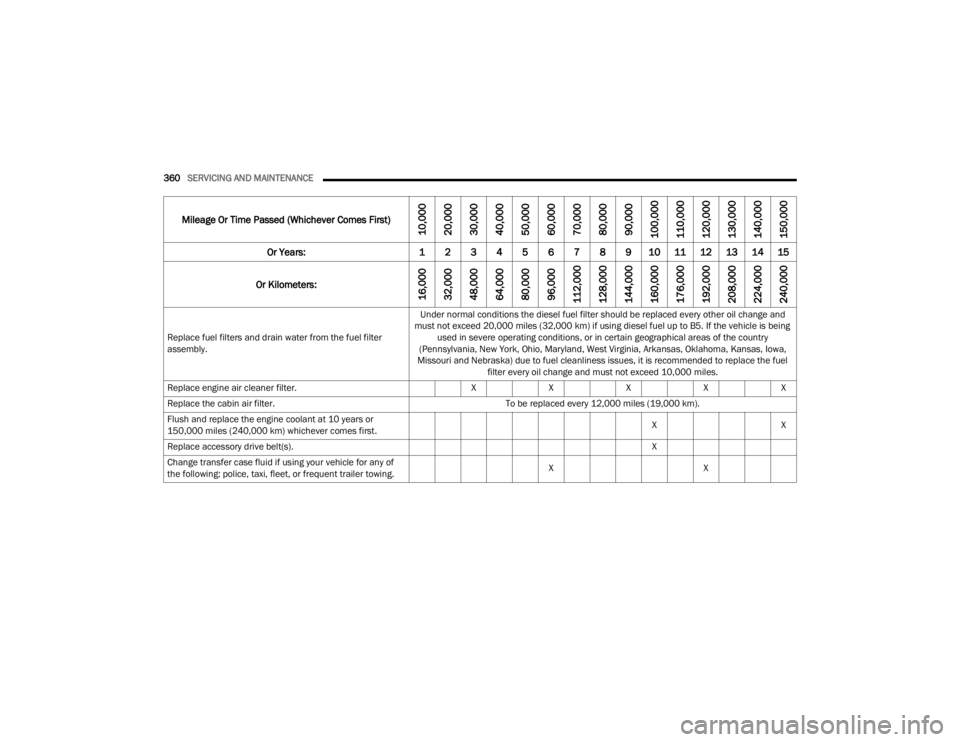
Replace fuel filters and drain water from the fuel filter
assembly. Under normal conditions the diesel fuel filter should be replaced every other oil change and
must not exceed 20,000 miles (32,000 km) if using diesel fuel up to B5. If the vehicle is being used in severe operating conditions, or in certain geographical areas of the country
(Pennsylvania, New York, Ohio, Maryland, West Virginia, Arkansas, Oklahoma, Kansas, Iowa,
Missouri and Nebraska) due to fuel cleanliness issues, it is recommended to replace the fuel filter every oil change and must not exceed 10,000 miles.
Replace engine air cleaner filter. XXXXX
Replace the cabin air filter. To be replaced every 12,000 miles (19,000 km).
Flush and replace the engine coolant at 10 years or
150,000 miles (240,000 km) whichever comes first. X
X
Replace accessory drive belt(s). X
Change transfer case fluid if using your vehicle for any of
the following: police, taxi, fleet, or frequent trailer towing. X
X
Mileage Or Time Passed (Whichever Comes First)
10,000
20,000
30,000
40,000
50,000
60,000
70,000
80,000
90,000
100,000
110,000
120,000
130,000
140,000
150,000
Or Years: 1 2 3 4 5 6 7 8 9 10 11 12 13 14 15
Or Kilometers:
16,000
32,000
48,000
64,000
80,000
96,000
112,000
128,000
144,000
160,000
176,000
192,000
208,000
224,000
240,000
23_JT_OM_EN_USC_t.book Page 360
Page 366 of 448
364SERVICING AND MAINTENANCE
(Continued)
CHECKING OIL LEVEL
To ensure proper engine lubrication, the engine oil
must be maintained at the correct level. Check the
oil level at regular intervals, such as every fuel
stop. The best time to check the engine oil level is
about five minutes after a fully warmed up engine
is shut off.
Checking the oil while the vehicle is on level ground
will improve the accuracy of the oil level readings.
There are four possible dipstick types:
Crosshatched zone.
Crosshatched zone marked SAFE.
Crosshatched zone marked with MIN at the low
end of the range and MAX at the high end of the
range.
Crosshatched zone marked with dimples at the
MIN and the MAX ends of the range.
NOTE:Always maintain the oil level within the crosshatch
markings on the dipstick.
Adding 1 qt (1 L) of oil when the reading is at the
low end of the dipstick range will raise the oil level
to the high end of the range marking.
ADDING WASHER FLUID
The fluid reservoir is located in the engine
compartment. Be sure to check the fluid level at
regular intervals. Fill the reservoir with windshield
washer solvent only (not radiator antifreeze). When
refilling the washer fluid reservoir, take some
washer fluid and apply it to a cloth or towel and
wipe clean the wiper blades; this will help blade
performance.
To prevent freeze-up of your windshield washer
system in cold weather, select a solution or mixture
that meets or exceeds the temperature range of
your climate. This rating information can be found
on most washer fluid containers.
MAINTENANCE-FREE BATTERY
Your vehicle is equipped with a maintenance-free
battery. You will never have to add water, and
periodic maintenance is not required.
CAUTION!
Overfilling or underfilling the crankcase will
cause aeration or loss of oil pressure. This could
damage your engine.
WARNING!
Commercial windshield washer solvents are
flammable. They could ignite and burn you. Care
must be exercised when filling or working around
the washer solution.
WARNING!
Battery fluid is a corrosive acid solution and
can burn or even blind you. Do not allow
battery fluid to contact your eyes, skin, or
clothing. Do not lean over a battery when
attaching clamps. If acid splashes in eyes or
on skin, flush the area immediately with large
amounts of water Úpage 343.
Battery gas is flammable and explosive. Keep
flame or sparks away from the battery. Do not
use a booster battery or any other booster
source with an output greater than 12 Volts.
Do not allow cable clamps to touch each
other.
Battery posts, terminals, and related accesso -
ries contain lead and lead compounds. Wash
hands after handling.
23_JT_OM_EN_USC_t.book Page 364
Page 377 of 448
SERVICING AND MAINTENANCE375
NOTE:Life expectancy of wiper blades varies depending
on geographical area and frequency of use. If chat -
tering, marks, water lines, or wet spots are
present, clean the wiper blades or replace as
necessary.
The wiper blades and wiper arms should be
inspected periodically, not just when wiper
performance problems are experienced. This
inspection should include the following points:
Wear or uneven edges
Foreign material
Hardening or cracking
Deformation or fatigue
If a wiper blade or wiper arm is damaged, replace
the affected wiper arm or blade with a new unit. Do
not attempt to repair a wiper arm or blade that is
damaged.
Wiper Blade Removal/Installation
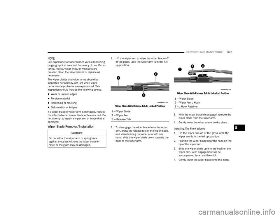
1. Lift the wiper arm to raise the wiper blade off of the glass, until the wiper arm is in the full
up position.
Wiper Blade With Release Tab In Locked Position
2. To disengage the wiper blade from the wiper arm, press the release tab on the wiper blade,
and while holding the wiper arm with one
hand, slide the wiper blade down towards the
base of the wiper arm.
Wiper Blade With Release Tab In Unlocked Position
3. With the wiper blade disengaged, remove the wiper blade from the wiper arm.
4. Gently lower the wiper arm onto the glass.
Installing The Front Wipers
1. Lift the wiper arm off of the glass, until the wiper arm is in the full up position.
2. Position the wiper blade near the hook on the tip of the wiper arm.
3. Slide the wiper blade up into the hook on the wiper arm, latch engagement will be
accompanied by an audible click.
4. Gently lower the wiper blade onto the glass.
CAUTION!
Do not allow the wiper arm to spring back
against the glass without the wiper blade in
place or the glass may be damaged.
1 — Wiper Blade
2 — Wiper Arm
3 — Release Tab
1 — Wiper Blade
2 — Wiper Arm J Hook
3 — J Hook Retainer
8
23_JT_OM_EN_USC_t.book Page 375
Page 378 of 448
376SERVICING AND MAINTENANCE
(Continued)
EXHAUST SYSTEM
The best protection against carbon monoxide entry
into the vehicle body is a properly maintained
engine exhaust system.
If you notice a change in the sound of the exhaust
system, or if the exhaust fumes can be detected
inside the vehicle, or when the underside or rear of
the vehicle is damaged, have an authorized
technician inspect the complete exhaust system
and adjacent body areas for broken, damaged,
deteriorated, or mispositioned parts. Open seams
or loose connections could permit exhaust fumes
to seep into the passenger compartment. In
addition, have the exhaust system inspected each
time the vehicle is raised for lubrication or oil
change. Replace as required. Under normal operating conditions, the catalytic
converter will not require maintenance. However, it
is important to keep the engine properly tuned to
ensure proper catalyst operation and prevent
possible catalyst damage.
NOTE:Intentional tampering with emissions control
systems can result in civil penalties being
assessed against you.
In unusual situations involving grossly
malfunctioning engine operation, a scorching odor
may suggest severe and abnormal catalyst
overheating. If this occurs, stop the vehicle, turn off
the engine and allow it to cool. Service, including a
tune-up to manufacturer's specifications, should
be obtained immediately.
To minimize the possibility of catalytic converter
damage:
Do not interrupt the ignition when the transmis
-
sion is in gear and the vehicle is in motion.
Do not try to start the vehicle by pushing or
towing the vehicle.
Do not idle the engine with any ignition compo -
nents disconnected or removed, such as when
diagnostic testing, or for prolonged periods
during very rough idle or malfunctioning oper -
ating conditions.
WARNING!
Exhaust gases can injure or kill. They contain
Carbon Monoxide (CO), which is colorless and
odorless. Breathing it can make you uncon -
scious and can eventually poison you. To
avoid breathing CO see Ú page 328.
A hot exhaust system can start a fire if you
park over materials that can burn, such as
grass or leaves, and those items that come
into contact with your exhaust system. Do not
park or operate your vehicle in areas where
your exhaust system can contact anything that
can burn.
CAUTION!
The catalytic converter requires the use of
unleaded fuel only. Leaded gasoline will
destroy the effectiveness of the catalyst as an
emissions control device, may seriously
reduce engine performance and cause
serious damage to the engine.
Damage to the catalytic converter can result if
your vehicle is not kept in proper operating
condition. In the event of engine malfunction,
particularly involving engine misfire or other
apparent loss of performance, have your
vehicle serviced promptly. Continued opera -
tion of your vehicle with a severe malfunction
could cause the converter to overheat,
resulting in possible damage to the converter
and vehicle.
WARNING!
23_JT_OM_EN_USC_t.book Page 376
Page 390 of 448
388SERVICING AND MAINTENANCE
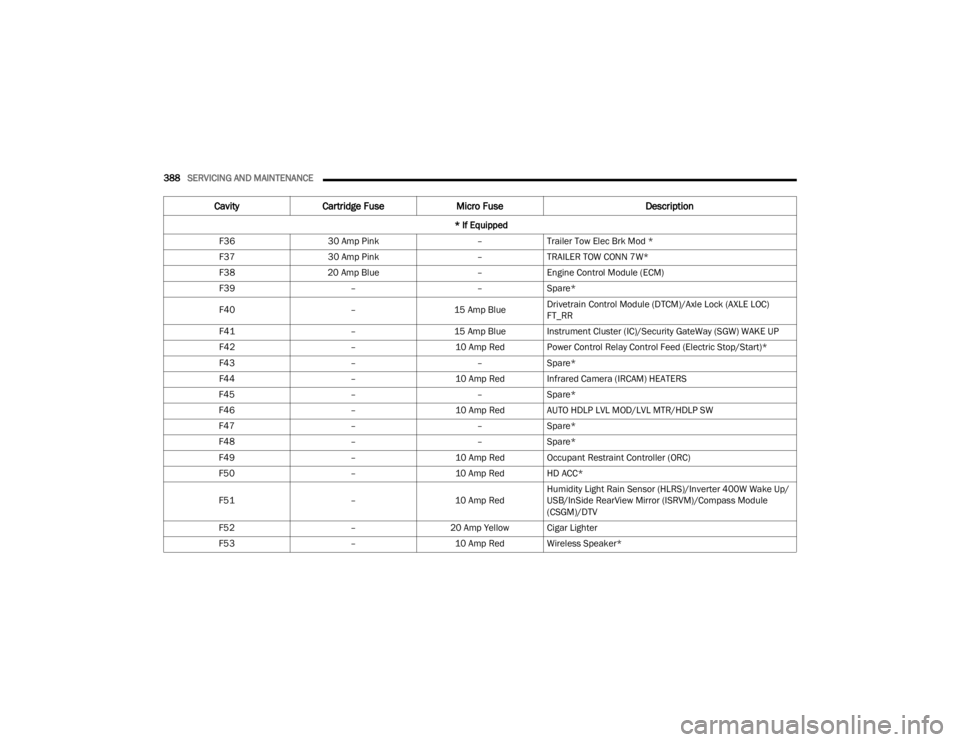
F36 30 Amp Pink –Trailer Tow Elec Brk Mod *
F37 30 Amp Pink –TRAILER TOW CONN 7W*
F38 20 Amp Blue –Engine Control Module (ECM)
F39 ––Spare*
F40 –15 Amp BlueDrivetrain Control Module (DTCM)/Axle Lock (AXLE LOC)
FT_RR
F41 –15 Amp Blue Instrument Cluster (IC)/Security GateWay (SGW) WAKE UP
F42 –10 Amp Red Power Control Relay Control Feed (Electric Stop/Start)*
F43 ––Spare*
F44 –10 Amp Red Infrared Camera (IRCAM) HEATERS
F45 ––Spare*
F46 –10 Amp Red AUTO HDLP LVL MOD/LVL MTR/HDLP SW
F47 ––Spare*
F48 ––Spare*
F49 –10 Amp Red Occupant Restraint Controller (ORC)
F50 –10 Amp Red HD ACC*
F51 –10 Amp RedHumidity Light Rain Sensor (HLRS)/Inverter 400W Wake Up/
USB/InSide RearView Mirror (ISRVM)/Compass Module
(CSGM)/DTV
F52 –20 Amp Yellow Cigar Lighter
F53 –10 Amp Red Wireless Speaker*
CavityCartridge Fuse Micro Fuse Description
* If Equipped
23_JT_OM_EN_USC_t.book Page 388
Page 392 of 448
390SERVICING AND MAINTENANCE
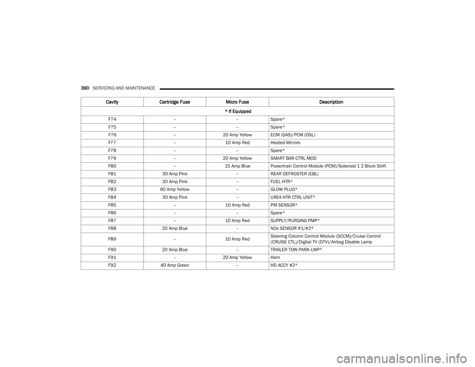
F74 ––Spare*
F75 ––Spare*
F76 –20 Amp Yellow ECM (GAS)/PCM (DSL)
F77 –10 Amp Red Heated Mirrors
F78 ––Spare*
F79 –20 Amp Yellow SMART BAR CTRL MOD
F80 –15 Amp Blue Powertrain Control Module (PCM)/Solenoid 1 2 Block Shift
F81 30 Amp Pink –REAR DEFROSTER (EBL)
F82 30 Amp Pink –FUEL HTR*
F83 60 Amp Yellow –GLOW PLUG*
F84 30 Amp Pink –UREA HTR CTRL UNIT*
F85 –10 Amp Red PM SENSOR*
F86 ––Spare*
F87 –10 Amp Red SUPPLY/PURGING PMP*
F88 20 Amp Blue –NOx SENSOR #1/#2*
F89 –10 Amp RedSteering Column Control Module (SCCM)/Cruise Control
(CRUISE CTL)/Digital TV (DTV)/Airbag Disable Lamp
F90 20 Amp Blue –TRAILER TOW PARK LMP*
F91 –20 Amp Yellow Horn
F92 40 Amp Green –HD ACCY #2*
Cavity Cartridge Fuse Micro Fuse Description
* If Equipped
23_JT_OM_EN_USC_t.book Page 390
Page 393 of 448
SERVICING AND MAINTENANCE391
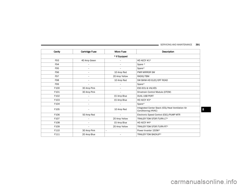
F93 40 Amp Green –HD ACCY #1*
F94 ––Spare *
F95 ––Spare*
F96 –10 Amp Red PWR MIRROR SW
F97 –20 Amp Yellow RADIO/TBM
F98 –10 Amp Red SW BANK-HD ELEC/OFF ROAD
F99 ––Spare*
F100 30 Amp Pink –ESC-ECU & VALVES
F101 30 Amp Pink –Drivetrain Control Module (DTCM)
F102 –15 Amp Blue DUAL USB PORT
F103 –15 Amp Blue HD ACCY #3*
F104 ––Spare*
F105 –10 Amp RedIntegrated Center Stack (ICS)/Heat Ventilation Air
Conditioning (HVAC)
F106 50 Amp Red –Electronic Speed Control (ESC)/PUMP MTR
F107 –20 Amp Yellow TRAILER TOW STOP/TURN LT*
F108 –15 Amp Blue HD ACCY #4*
F109 –20 Amp Yellow TRAILER TOW STOP/TURN RT*
F110 30 Amp Pink – Power Inverter 150W*
F111 20 Amp Blue –TRAILER TOW BACKUP*
Cavity Cartridge Fuse Micro Fuse Description
* If Equipped
8
23_JT_OM_EN_USC_t.book Page 391
Page 395 of 448
SERVICING AND MAINTENANCE393
Bulb Replacement
NOTE:Lens fogging can occur under certain atmospheric
conditions. This will usually clear as atmospheric
conditions occur to allow the condensation to
change back into a vapor. Turning the lamps on will
usually accelerate the clearing process.
HALOGEN HEADLAMPS — IF EQUIPPED
See the following steps to replace:
1. Open hood and support using prop rod.
2. Remove the front grille. Turn the retainers
along the top a quarter turn counterclockwise
and remove.
3. Pull the bottom of the grille away, starting at one side and working toward the other. 4. Remove the three screws holding the
headlamp to the vehicle.
5. Remove lamp from the vehicle.
6. Remove the lamp from the collar.
7. Grab the bulb and turn a quarter turn counter -
clockwise.
8. Pull the bulb from the housing.
9. Push connector locking tab to the unlock position.
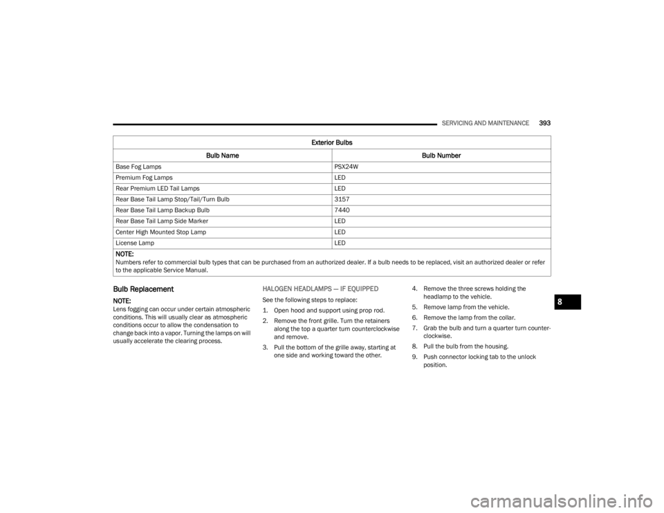
Base Fog Lamps
PSX24W
Premium Fog Lamps LED
Rear Premium LED Tail Lamps LED
Rear Base Tail Lamp Stop/Tail/Turn Bulb 3157
Rear Base Tail Lamp Backup Bulb 7440
Rear Base Tail Lamp Side Marker LED
Center High Mounted Stop Lamp LED
License Lamp LED
NOTE: Numbers refer to commercial bulb types that can be purchased from an authorized dealer. If a bulb needs to be replaced, visit an authorized dealer or refer
to the applicable Service Manual.
Exterior Bulbs
Bulb Name Bulb Number
8
23_JT_OM_EN_USC_t.book Page 393
Page 402 of 448
400SERVICING AND MAINTENANCE
Tire Loading And Tire Pressure
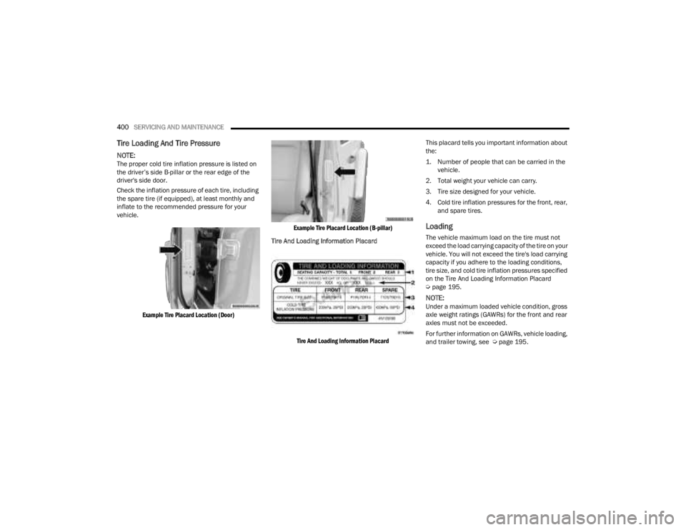
NOTE:The proper cold tire inflation pressure is listed on
the driver’s side B-pillar or the rear edge of the
driver's side door.
Check the inflation pressure of each tire, including
the spare tire (if equipped), at least monthly and
inflate to the recommended pressure for your
vehicle.
Example Tire Placard Location (Door) Example Tire Placard Location (B-pillar)
Tire And Loading Information Placard
Tire And Loading Information Placard
This placard tells you important information about
the:
1. Number of people that can be carried in the
vehicle.
2. Total weight your vehicle can carry.
3. Tire size designed for your vehicle.
4. Cold tire inflation pressures for the front, rear, and spare tires.
Loading
The vehicle maximum load on the tire must not
exceed the load carrying capacity of the tire on your
vehicle. You will not exceed the tire's load carrying
capacity if you adhere to the loading conditions,
tire size, and cold tire inflation pressures specified
on the Tire And Loading Information Placard
Úpage 195.
NOTE:Under a maximum loaded vehicle condition, gross
axle weight ratings (GAWRs) for the front and rear
axles must not be exceeded.
For further information on GAWRs, vehicle loading,
and trailer towing, see Ú page 195.
23_JT_OM_EN_USC_t.book Page 400
Page 403 of 448
SERVICING AND MAINTENANCE401
To determine the maximum loading conditions of
your vehicle, locate the statement “The combined
weight of occupants and cargo should never
exceed XXX kg or XXX lbs” on the Tire And Loading
Information Placard. The combined weight of
occupants, cargo/luggage and trailer tongue
weight (if applicable) should never exceed the
weight referenced here.
Steps For Determining Correct Load Limit—
(1) Locate the statement “The combined
weight of occupants and cargo should
never exceed XXX kg or XXX lbs.” on your
vehicle's placard.
(2) Determine the combined weight of
the driver and passengers that will be
riding in your vehicle.
(3) Subtract the combined weight of the
driver and passengers from XXX kg or
XXX lbs.
(4) The resulting figure equals the
available amount of cargo and luggage
load capacity. For example, if “XXX”
amount equals 1400 lbs. and there will
be five 150 lbs passengers in your
vehicle, the amount of available cargo and luggage load capacity is 650 lbs.
(1400-750 (5x150) = 650 lbs.)
(5) Determine the combined weight of
luggage and cargo being loaded on the
vehicle. That weight may not safely
exceed the available cargo and luggage
load capacity calculated in Step 4.
(6) If your vehicle will be towing a trailer,
load from your trailer will be transferred
to your vehicle. Consult this manual to
determine how this reduces the
available cargo and luggage load
capacity of your vehicle.
Metric Example For Load Limit
For example, if “XXX” amount equals 635 kg and
there will be five 68 kg passengers in your vehicle,
the amount of available cargo and luggage load
capacity is 295 kg (635-340 (5x68) = 295 kg) as
shown in step 4.
NOTE:
If your vehicle will be towing a trailer, load from
your trailer will be transferred to your vehicle.
The following table shows examples on how to
calculate total load, cargo/luggage, and towing
capacities of your vehicle with varying seating
configurations and number and size of occu
-pants. This table is for illustration purposes only
and may not be accurate for the seating and
load carry capacity of your vehicle.
For the following example, the combined weight
of occupants and cargo should never exceed
865 lbs (392 kg).
TIRES — GENERAL INFORMATION
Tire Pressure
Proper tire inflation pressure is essential to the
safe and satisfactory operation of your vehicle.
Four primary areas are affected by improper tire
pressure:
Safety
Fuel Economy
Tread Wear
Ride Comfort and Vehicle Stability
WARNING!
Overloading of your tires is dangerous.
Overloading can cause tire failure, affect vehicle
handling, and increase your stopping distance.
Use tires of the recommended load capacity for
your vehicle. Never overload them.
8
23_JT_OM_EN_USC_t.book Page 401