ad blue JEEP GLADIATOR 2023 Owners Manual
[x] Cancel search | Manufacturer: JEEP, Model Year: 2023, Model line: GLADIATOR, Model: JEEP GLADIATOR 2023Pages: 448, PDF Size: 17.37 MB
Page 6 of 448
4
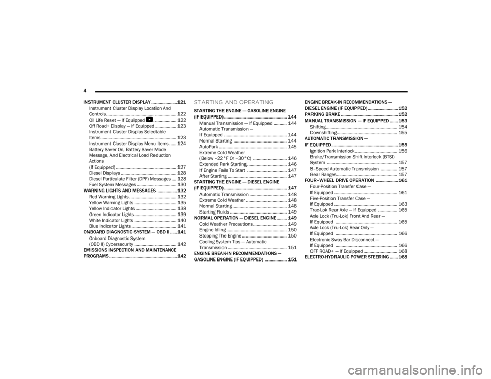
INSTRUMENT CLUSTER DISPLAY ...................... 121 Instrument Cluster Display Location And
Controls .......................................................... 122
Oil Life Reset — If Equipped
S
................... 122
Off Road+ Display — If Equipped .................. 123
Instrument Cluster Display Selectable
Items .............................................................. 123
Instrument Cluster Display Menu Items ...... 124
Battery Saver On, Battery Saver Mode
Message, And Electrical Load Reduction
Actions
(If Equipped) .................................................. 127
Diesel Displays .............................................. 128 Diesel Particulate Filter (DPF) Messages .... 128Fuel System Messages ................................. 130
WARNING LIGHTS AND MESSAGES ................. 132
Red Warning Lights ....................................... 132
Yellow Warning Lights ................................... 135Yellow Indicator Lights .................................. 138
Green Indicator Lights................................... 139White Indicator Lights ................................... 140Blue Indicator Lights ..................................... 141
ONBOARD DIAGNOSTIC SYSTEM — OBD II ...... 141
Onboard Diagnostic System
(OBD II) Cybersecurity ................................... 142
EMISSIONS INSPECTION AND MAINTENANCE
PROGRAMS .......................................................... 142
STARTING AND OPERATING
STARTING THE ENGINE — GASOLINE ENGINE
(IF EQUIPPED) ...................................................... 144
Manual Transmission — If Equipped ........... 144Automatic Transmission —
If Equipped .................................................... 144
Normal Starting ............................................ 144
AutoPark ........................................................ 145Extreme Cold Weather
(Below –22°F Or −30°C) ............................ 146
Extended Park Starting ................................. 146
If Engine Fails To Start ................................. 147
After Starting ................................................. 147
STARTING THE ENGINE — DIESEL ENGINE
(IF EQUIPPED) ...................................................... 147
Automatic Transmission ............................... 148
Extreme Cold Weather .................................. 148
Normal Starting ............................................. 148Starting Fluids ............................................... 149
NORMAL OPERATION — DIESEL ENGINE ......... 149
Cold Weather Precautions ............................ 149
Engine Idling .................................................. 150
Stopping The Engine ..................................... 150
Cooling System Tips — Automatic
Transmission ................................................. 151
ENGINE BREAK-IN RECOMMENDATIONS —
GASOLINE ENGINE (IF EQUIPPED) ................... 151 ENGINE BREAK-IN RECOMMENDATIONS —
DIESEL ENGINE (IF EQUIPPED) .......................... 152
PARKING BRAKE ................................................. 152
MANUAL TRANSMISSION — IF EQUIPPED ....... 153
Shifting........................................................... 154
Downshifting.................................................. 155
AUTOMATIC TRANSMISSION —
IF EQUIPPED ......................................................... 155
Ignition Park Interlock................................... 156
Brake/Transmission Shift Interlock (BTSI)
System .......................................................... 1578–Speed Automatic Transmission .............. 157
Gear Ranges .................................................. 157
FOUR–WHEEL DRIVE OPERATION ................... 161
Four-Position Transfer Case —
If Equipped .................................................... 161
Five-Position Transfer Case —
If Equipped .................................................... 163
Trac-Lok Rear Axle — If Equipped ................ 165Axle Lock (Tru-Lok) Front And Rear —
If Equipped ................................................... 165
Axle Lock (Tru-Lok) Rear Only —
If Equipped ................................................... 166
Electronic Sway Bar Disconnect —
If Equipped ................................................... 166
OFF ROAD+ — If Equipped ............................ 168
ELECTRO-HYDRAULIC POWER STEERING ....... 168
23_JT_OM_EN_USC_t.book Page 4
Page 15 of 448
13
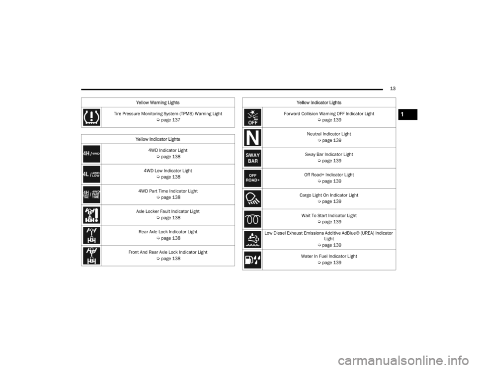
Tire Pressure Monitoring System (TPMS) Warning Light Úpage 137
Yellow Indicator Lights 4WD Indicator Light Úpage 138
4WD Low Indicator Light Úpage 138
4WD Part Time Indicator Light Úpage 138
Axle Locker Fault Indicator Light Úpage 138
Rear Axle Lock Indicator Light Úpage 138
Front And Rear Axle Lock Indicator Light Úpage 138
Yellow Warning Lights
Forward Collision Warning OFF Indicator Light
Úpage 139
Neutral Indicator Light Úpage 139
Sway Bar Indicator Light Úpage 139
Off Road+ Indicator Light Úpage 139
Cargo Light On Indicator Light Úpage 139
Wait To Start Indicator Light Úpage 139
Low Diesel Exhaust Emissions Additive AdBlue® (UREA) Indicator Light
Ú page 139
Water In Fuel Indicator Light Úpage 139
Yellow Indicator Lights1
23_JT_OM_EN_USC_t.book Page 13
Page 16 of 448
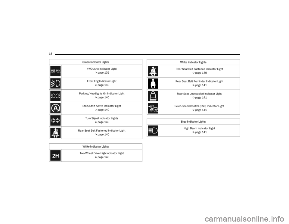
14 Green Indicator Lights4WD Auto Indicator Light Úpage 139
Front Fog Indicator Light Úpage 140
Parking/Headlights On Indicator Light Úpage 140
Stop/Start Active Indicator Light Úpage 140
Turn Signal Indicator Lights Úpage 140
Rear Seat Belt Fastened Indicator Light Úpage 140
White Indicator Lights
Two Wheel Drive High Indicator Light Úpage 140
Rear Seat Belt Fastened Indicator Light
Úpage 140
Rear Seat Belt Reminder Indicator Light Úpage 141
Rear Seat Unoccupied Indicator Light Úpage 141
Selec-Speed Control (SSC) Indicator Light Úpage 141
Blue Indicator Lights High Beam Indicator Light Úpage 141
White Indicator Lights
23_JT_OM_EN_USC_t.book Page 14
Page 65 of 448
GETTING TO KNOW YOUR VEHICLE63
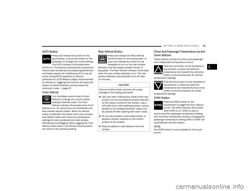
AUTO Button
Press and release this button on the
touchscreen, or push the button on the
faceplate, to change the current setting.
The AUTO indicator illuminates when
AUTO is on. This feature automatically controls the
interior cabin temperature by adjusting distribution
and blower speed. Air conditioning (A/C) may be
active during AUTO operation to improve
performance. AUTO Mode is highly recommended
for efficiency. Toggling this function will cause the
system to switch between manual mode and
automatic mode Ú page 67.
Front Defrost
Turn the Mode control knob to Front
Defrost to change the current airflow
setting to Defrost mode. The Front
Defrost indicator illuminates when Front
Defrost is on. Air comes from the windshield and
side window demist outlets. When the defrost
button is selected, the blower level may increase.
Use Defrost mode with maximum temperature
settings for best windshield and side window
defrosting and defogging. When toggling the front
defrost mode button, the Climate Control system
will return to the previous setting.
Rear Defrost Button
Press and release the Rear Defrost
Control button on the touchscreen, or
push and release the button on the
faceplate to turn on the rear window
defroster and the heated outside mirrors (if
equipped). The Rear Defrost indicator illuminates
when the rear window defroster is on. The rear
window defroster automatically turns off after
10 minutes.
Driver And Passenger Temperature Up And
Down Buttons
These buttons provide the driver and passenger
with independent temperature control.
Push the red button on the faceplate or
touchscreen or press and slide the
temperature bar towards the red arrow
button on the touchscreen for warmer
temperature settings.
Push the blue button on the faceplate or
touchscreen or press and slide the
temperature bar towards the blue arrow
button on the touchscreen for cooler
temperature settings.
SYNC Button
Press the SYNC button on the
touchscreen to toggle the Sync feature
on/off. The SYNC indicator illuminates
when SYNC is on. SYNC is used to
synchronize the passenger temperature setting
with the driver temperature setting. Changing the
passenger temperature setting while in SYNC will
automatically exit this feature.
NOTE:The SYNC button is only available on the touch-
screen.
CAUTION!
Failure to follow these cautions can cause
damage to the heating elements:
Use care when washing the inside of the rear
window. Do not use abrasive window cleaners
on the interior surface of the window. Use a
soft cloth and a mild washing solution, wiping
parallel to the heating elements. Labels can
be peeled off after soaking with warm water.
Do not use scrapers, sharp instruments, or
abrasive window cleaners on the interior
surface of the window.
Keep all objects a safe distance from the
window.
2
23_JT_OM_EN_USC_t.book Page 63
Page 74 of 448
72GETTING TO KNOW YOUR VEHICLE
Depending on your vehicle’s specifications, the USB
port may contain playback capabilities and will allow
you to play music from your smartphone device or
USB devices through your vehicle’s sound system.
A third and fourth USB port are located behind the
center console, above the power inverter. Both
ports are charge only.
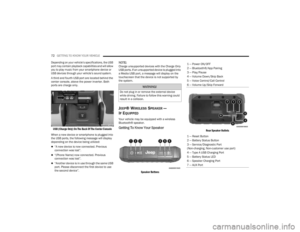
USB (Charge Only) On The Back Of The Center Console
When a new device or smartphone is plugged into
the USB ports, the following message will display
depending on the device being utilized:
“A new device is now connected. Previous
connection was lost”.
“(Phone Name) now connected. Previous
connection was lost”.
“Another device is in use through the same USB
port. Please disconnect the first device to use
the second device”.
NOTE:Charge unsupported devices with the Charge Only
USB ports. If an unsupported device is plugged into
a Media USB port, a message will display on the
touchscreen that the device is not supported by
the system.
JEEP® WIRELESS SPEAKER —
I
F EQUIPPED
Your vehicle may be equipped with a wireless
Bluetooth® speaker.
Getting To Know Your Speaker
Speaker Buttons Rear Speaker Outlets
WARNING!
Do not plug in or remove the external device
while driving. Failure to follow this warning could
result in a collision.
1 — Power ON/OFF
2 — Bluetooth®/App Pairing
3 — Play/Pause
4 — Volume Down/Skip Back
5 — Voice Control/Call Control
6 — Volume Up/Skip Forward
1 — Reset Button
2 — Battery Status Button
3 — Service/Diagnostic Port
(Non-charging, Non-customer use port)
4 — Type A USB Charging Port
5 — Battery Status LED
6 — Speaker Charging Port
7 — AUX Port
23_JT_OM_EN_USC_t.book Page 72
Page 77 of 448
GETTING TO KNOW YOUR VEHICLE75
Phone & Bluetooth® Pairing
A feature of the Jeep® wireless speaker is the
ability for the Jeep® wireless speaker to connect to
devices using Bluetooth®. Follow these simple
steps to connect a Bluetooth®-enabled device to
the Jeep® wireless speaker:
1. Press and hold the power button for 2-3 sec-
onds to turn the Jeep® wireless speaker on.
2. Turn “on” Bluetooth® for the device you desire to be connected to the Jeep® wireless
speaker. For instructions on how to turn on
and off Bluetooth® settings for the desired
device, refer to the device’s user manual.
3. When powered on, the Jeep® wireless speaker will automatically enter pairing mode.
To pair a second device, press and hold the
Bluetooth® button for 2-3 seconds, until an
audio cue is heard. Then go to the devices’
Bluetooth® settings and select “Jeep®
Speaker” from the list.
The Jeep® wireless speaker will remember the last
eight devices it has paired with.
NOTE:If the Jeep® wireless speaker is left on with an
inactive Bluetooth® connection for 30 minutes, it
will automatically turn off. The Jeep® wireless
speaker can be turned on again by pressing and
holding the power button for 2-3 seconds.
Resetting Your Jeep® Wireless Speaker
To reset the Jeep® wireless speaker to its original
factory setting, press and hold the reset button
under the back cover for 8-10 seconds.
Speakerphone
The speakerphone feature can be used by
pressing the “Voice Control” button on the Jeep®
wireless speaker. This feature can be used to
answer and end calls over the speakerphone.
Volume And Playback Control
Volume can be increased or decreased by briefly
pressing the + button or - button. When the
maximum volume is reached, an audio cue will
sound.
To skip to the next track, press and hold the
+ button. To go to the previous track, press the
- button.
Qualcomm TrueWireless™ Stereo
A feature of the Jeep® wireless speaker is being
able to pair two Jeep® wireless speakers together
for Qualcomm TrueWireless™ Stereo. This feature
allows for two Jeep® wireless speakers to play left
and right stereo sound. Below are the steps needed for Qualcomm
TrueWireless™ Stereo:
1. Push and hold the power button on both
Jeep® wireless speakers until both speakers
turn on.
2. Place both speakers into Qualcomm TrueWireless™ Stereo pairing mode. This can
be achieved by pressing and holding the
Battery Status button on both speakers until
an audio notification is heard from both
speakers.
3. Connect one of the Jeep® wireless speakers to the Bluetooth® source. Refer to previous
section “Phone & Bluetooth® Pairing” for
additional information.
4. Once the Jeep® wireless speaker is connected to the Bluetooth® device, audio will be played
from both speakers.
NOTE:While in Qualcomm TrueWireless™ Stereo mode,
the volume will not have independent speaker
control. Pushing the Up or Down Volume button on
either Jeep® wireless speaker will affect the audio
output on both, as well as volume adjustments on
the Bluetooth® device.
2
23_JT_OM_EN_USC_t.book Page 75
Page 78 of 448
76GETTING TO KNOW YOUR VEHICLE
Waterproof Features
The Jeep® wireless speaker is IP67 waterproof
certified with design in mind to withstand rainfall,
waterjets, splashing and being submerged in up to
3 ft (1 m) of water for up to 30 minutes.
Warnings, Caution & Legal Information
To reduce the risk of fire or electric shock, do not
expose the Jeep® wireless speaker to rain or
moisture while charging. The Jeep® wireless
speaker should not be exposed to dripping or
splashing, and objects filled with liquids, such as
vases, should not be placed on or near it while
being charged or charging other devices. As with
any electronic products, use care not to spill liquids
into any part of the product. Liquids can cause a
failure and/or a fire hazard. The power supply must
be used indoors only. Make no modifications to the
product or accessories. Unauthorized alterations
may compromise safety, regulatory compliance,
and system performance, and will void the
warranty. Do not place any flame sources, such as
lighted candles, on or near the Jeep® wireless speaker. The Jeep® wireless speaker contains
small parts that may be a choking hazard and is
not suitable for children under age 3. Do not
continue charging the battery if it does not reach
full charge within the specified charging time.
Overcharging may cause the battery to become
hot, rupture, or ignite. If you see any heat
deformation or leakage, properly dispose of the
battery. Do not attempt to charge the battery in
temperatures outside the range of 32°- 104°F
(0° - 40°C). If the battery begins to leak, do not
allow the liquid to come in contact with your skin or
eyes. If contact has been made, wash the affected
area with plenty of water and seek medical
attention immediately. Do not expose the Jeep®
wireless speaker or battery to excessive heat,
including direct sunlight or fire. Do not store or use
inside cars in hot weather, where it can be exposed
to temperatures in excess of 115°F (60°C). Doing
so may cause the battery and power supply to
generate heat, rupture, or ignite. Using the Jeep®
wireless speaker in this manner also may result in
a loss of performance and a shortened life
expectancy. Extended exposure to direct sunlight
may damage the external appearance and
material qualities. Do not step on, throw, or drop
batteries or the power supply or device, or expose
them to a strong shock. Do not pierce, crush, dent,
or deform the batteries or power supply in any way.
If either becomes deformed, properly dispose of it.
Do not short-circuit batteries. Do not attempt to service the Jeep® wireless speaker yourself.
Opening or removing covers may expose you to
dangerous voltages or other hazards and will void
the manufacturer’s warranty. To prevent risk of fire
or electric shock, avoid overloading wall outlets,
extension cords, or integral convenience
receptacles. Your Bluetooth® device (mobile
phone, music player, tablet, laptop, etc.) must
support the A2DP Bluetooth® profile in order to
work wirelessly with your Jeep® wireless speaker.
The A2DP profile is supported by most recent
mobile products with built-in Bluetooth®
capability. Please refer to your device’s user
manual for details and instruction regarding the
Bluetooth® profiles it supports. This device
complies with part 15 of the FCC Rules. Operation
is subject to the following two conditions: (1) This
device may not cause harmful interference, and
(2) this device must accept any interference
received, including interference that may cause
undesired operation.
Jeep® follows Safety Instruction for CE- LV. Do not
operate products in temperatures outside the
range of -5 to 40°C. Operating Frequency Band:
2402 MHz to 2480 MHz. Maximum RF power:
6 dBm EIRP. Do not install this equipment in a
confined space or building, such as a bookcase or
similar unit that is not well-ventilated. The
ventilation should not be impeded by covering the
ventilation openings with items such as
newspaper, tablecloths, curtains etc.
WARNING!
Any modifications or alterations to this vehicle
could seriously affect its roadworthiness and
safety and may lead to a collision resulting in
serious injury or death.
23_JT_OM_EN_USC_t.book Page 76
Page 79 of 448
GETTING TO KNOW YOUR VEHICLE77
NOTE:Please refer to the information on the bottom of
the Jeep® wireless speaker for electrical and
safety information before installing or operating
the Jeep® wireless speaker. Directive 2014/53/EU Article 10 Obligations of
Manufacturers
2. Manufacturers shall ensure that radio
equipment shall be so constructed that it can be
operated in at least one Member State without
infringing applicable requirements on the use of
radio spectrum.
10. In cases of restrictions on putting in to service
or of requirements for authorization of use,
information available on the packaging shall allow
the identification of the Member States or the
geographical area within a Member State where
restrictions on putting into service or requirements
for authorization of use exist. The Commission may
adopt implementing acts specifying how to present
that information. Those implementing acts shall be
adopted in accordance with the advisory
procedure referred to in Article 45 (2).
The Bluetooth® word mark and logos are
registered trademarks owned by Bluetooth SIG,
Inc. and any use of such marks by FCA US LLC is
under license. Other trademarks and trade names
are those of their respective owners.
POWER OUTLETS
There is a 12 Volt (13 A) auxiliary power outlet that
can provide power for accessories designed for
use with the standard power outlet adapters.
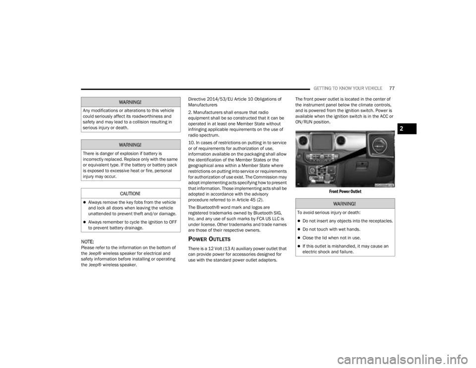
The front power outlet is located in the center of
the instrument panel below the climate controls,
and is powered from the ignition switch. Power is
available when the ignition switch is in the ACC or
ON/RUN position.
Front Power Outlet
WARNING!
Any modifications or alterations to this vehicle
could seriously affect its roadworthiness and
safety and may lead to a collision resulting in
serious injury or death.
WARNING!
There is danger of explosion if battery is
incorrectly replaced. Replace only with the same
or equivalent type. If the battery or battery pack
is exposed to excessive heat or fire, personal
injury may occur.
CAUTION!
Always remove the key fobs from the vehicle
and lock all doors when leaving the vehicle
unattended to prevent theft and/or damage.
Always remember to cycle the ignition to OFF
to prevent battery drainage.
WARNING!
To avoid serious injury or death:
Do not insert any objects into the receptacles.
Do not touch with wet hands.
Close the lid when not in use.
If this outlet is mishandled, it may cause an
electric shock and failure.
2
23_JT_OM_EN_USC_t.book Page 77
Page 82 of 448
80GETTING TO KNOW YOUR VEHICLE
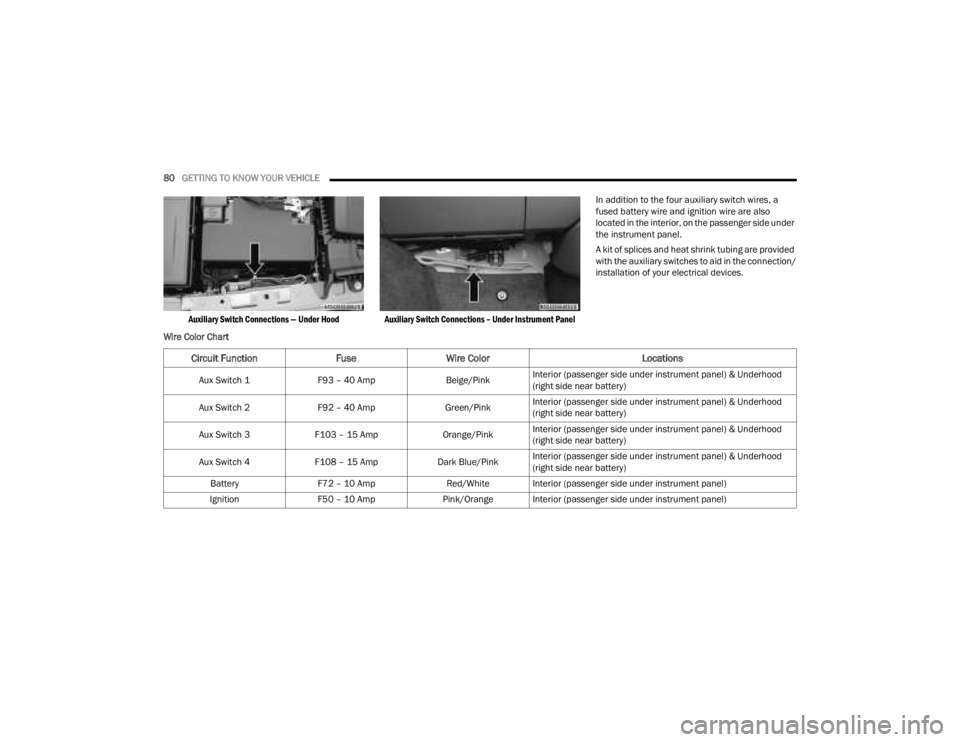
Auxiliary Switch Connections — Under Hood Auxiliary Switch Connections – Under Instrument Panel
In addition to the four auxiliary switch wires, a
fused battery wire and ignition wire are also
located in the interior, on the passenger side under
the instrument panel.
A kit of splices and heat shrink tubing are provided
with the auxiliary switches to aid in the connection/
installation of your electrical devices.
Wire Color Chart
Circuit Function FuseWire Color Locations
Aux Switch 1F93 – 40 Amp Beige/PinkInterior (passenger side under instrument panel) & Underhood
(right side near battery)
Aux Switch 2 F92 – 40 Amp Green/PinkInterior (passenger side under instrument panel) & Underhood
(right side near battery)
Aux Switch 3 F103 – 15 Amp Orange/PinkInterior (passenger side under instrument panel) & Underhood
(right side near battery)
Aux Switch 4 F108 – 15 Amp Dark Blue/PinkInterior (passenger side under instrument panel) & Underhood
(right side near battery)
Battery F72 – 10 Amp Red/White Interior (passenger side under instrument panel)
Ignition F50 – 10 Amp Pink/Orange Interior (passenger side under instrument panel)
23_JT_OM_EN_USC_t.book Page 80
Page 132 of 448
130GETTING TO KNOW YOUR INSTRUMENT PANEL
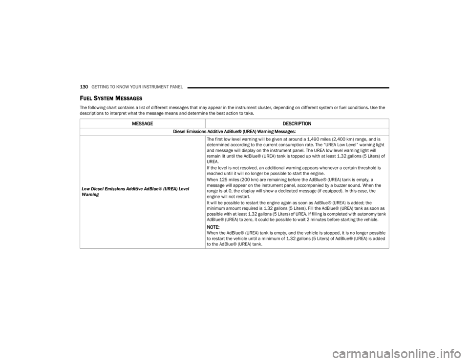
FUEL SYSTEM MESSAGES
The following chart contains a list of different messages that may appear in the instrument cluster, depending on different system or fuel conditions. Use the
descriptions to interpret what the message means and determine the best action to take.
MESSAGE DESCRIPTION
Diesel Emissions Additive AdBlue® (UREA) Warning Messages:
Low Diesel Emissions Additive AdBlue® (UREA) Level
Warning The first low level warning will be given at around a 1,490 miles (2,400 km) range, and is
determined according to the current consumption rate. The “UREA Low Level” warning light
and message will display on the instrument panel. The UREA low level warning light will
remain lit until the AdBlue® (UREA) tank is topped up with at least 1.32 gallons (5 Liters) of
UREA.
If the level is not resolved, an additional warning appears whenever a certain threshold is
reached until it will no longer be possible to start the engine.
When 125 miles (200 km) are remaining before the AdBlue® (UREA) tank is empty, a
message will appear on the instrument panel, accompanied by a buzzer sound. When the
range is at 0, the display will show a dedicated message (if equipped). In this case, the
engine will not restart.
It will be possible to restart the engine again as soon as AdBlue® (UREA) is added; the
minimum amount required is 1.32 gallons (5 Liters). Fill the AdBlue® (UREA) tank as soon as
possible with at least 1.32 gallons (5 Liters) of UREA. If filling is completed with autonomy tank
AdBlue® (UREA) to zero, it could be possible to wait 2 minutes before starting the vehicle.
NOTE:When the AdBlue® (UREA) tank is empty, and the vehicle is stopped, it is no longer possible
to restart the vehicle until a minimum of 1.32 gallons (5 Liters) of AdBlue® (UREA) is added
to the AdBlue® (UREA) tank.
23_JT_OM_EN_USC_t.book Page 130