auxiliary battery JEEP GLADIATOR 2023 Owners Manual
[x] Cancel search | Manufacturer: JEEP, Model Year: 2023, Model line: GLADIATOR, Model: JEEP GLADIATOR 2023Pages: 448, PDF Size: 17.37 MB
Page 79 of 448

GETTING TO KNOW YOUR VEHICLE77
NOTE:Please refer to the information on the bottom of
the Jeep® wireless speaker for electrical and
safety information before installing or operating
the Jeep® wireless speaker. Directive 2014/53/EU Article 10 Obligations of
Manufacturers
2. Manufacturers shall ensure that radio
equipment shall be so constructed that it can be
operated in at least one Member State without
infringing applicable requirements on the use of
radio spectrum.
10. In cases of restrictions on putting in to service
or of requirements for authorization of use,
information available on the packaging shall allow
the identification of the Member States or the
geographical area within a Member State where
restrictions on putting into service or requirements
for authorization of use exist. The Commission may
adopt implementing acts specifying how to present
that information. Those implementing acts shall be
adopted in accordance with the advisory
procedure referred to in Article 45 (2).
The Bluetooth® word mark and logos are
registered trademarks owned by Bluetooth SIG,
Inc. and any use of such marks by FCA US LLC is
under license. Other trademarks and trade names
are those of their respective owners.
POWER OUTLETS
There is a 12 Volt (13 A) auxiliary power outlet that
can provide power for accessories designed for
use with the standard power outlet adapters.
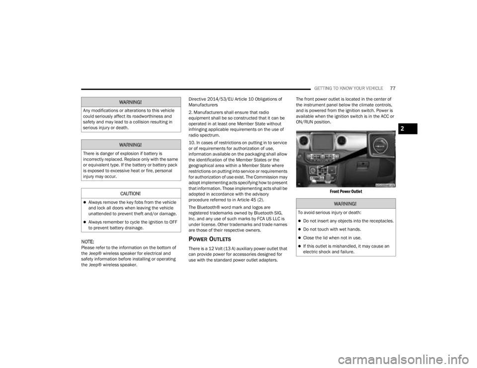
The front power outlet is located in the center of
the instrument panel below the climate controls,
and is powered from the ignition switch. Power is
available when the ignition switch is in the ACC or
ON/RUN position.
Front Power Outlet
WARNING!
Any modifications or alterations to this vehicle
could seriously affect its roadworthiness and
safety and may lead to a collision resulting in
serious injury or death.
WARNING!
There is danger of explosion if battery is
incorrectly replaced. Replace only with the same
or equivalent type. If the battery or battery pack
is exposed to excessive heat or fire, personal
injury may occur.
CAUTION!
Always remove the key fobs from the vehicle
and lock all doors when leaving the vehicle
unattended to prevent theft and/or damage.
Always remember to cycle the ignition to OFF
to prevent battery drainage.
WARNING!
To avoid serious injury or death:
Do not insert any objects into the receptacles.
Do not touch with wet hands.
Close the lid when not in use.
If this outlet is mishandled, it may cause an
electric shock and failure.
2
23_JT_OM_EN_USC_t.book Page 77
Page 81 of 448

GETTING TO KNOW YOUR VEHICLE79
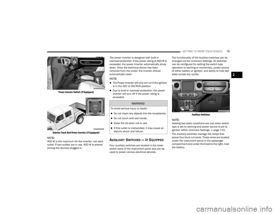
Power Inverter Switch (If Equipped)
Exterior Truck Bed Power Inverter (If Equipped)
NOTE:400 W is the maximum for the inverter, not each
outlet. If two outlets are in use, 400 W is shared
among the devices plugged in. The power inverter is designed with built-in
overload protection. If the power rating of 400 W is
exceeded, the power inverter automatically shuts
down. Once the electrical device has been
removed from the outlet, the inverter should
automatically reset.
NOTE:
The Power Inverter will only turn on if the ignition
is in the ACC or ON/RUN position.
Due to built-in overload protection, the power
inverter will turn off if the power rating is
exceeded.
AUXILIARY SWITCHES — IF EQUIPPED
Four auxiliary switches are located in the lower
switch bank of the instrument panel and can be
used to power various electrical devices.The functionality of the auxiliary switches can be
changed via the Uconnect Settings. All switches
can be configured for setting the switch type
operation to latching or momentary, power source
of either battery or ignition, and ability to hold last
state across key cycles.
Auxiliary Switches
NOTE:Holding last state conditions are met when switch
type is set to latching and power source is set to
ignition within Uconnect Settings Ú page 215.
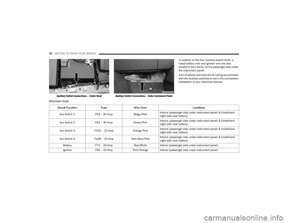
The auxiliary switches manage the relays that
power four blunt cut wires. These wires are located
under the instrument panel in the passenger
compartment and under the hood to the right, near
the battery.
WARNING!
To avoid serious injury or death:
Do not insert any objects into the receptacles.
Do not touch with wet hands.
Close the lid when not in use.
If this outlet is mishandled, it may cause an
electric shock and failure.
2
23_JT_OM_EN_USC_t.book Page 79
Page 82 of 448

80GETTING TO KNOW YOUR VEHICLE
Auxiliary Switch Connections — Under Hood Auxiliary Switch Connections – Under Instrument Panel
In addition to the four auxiliary switch wires, a
fused battery wire and ignition wire are also
located in the interior, on the passenger side under
the instrument panel.
A kit of splices and heat shrink tubing are provided
with the auxiliary switches to aid in the connection/
installation of your electrical devices.
Wire Color Chart
Circuit Function FuseWire Color Locations
Aux Switch 1F93 – 40 Amp Beige/PinkInterior (passenger side under instrument panel) & Underhood
(right side near battery)
Aux Switch 2 F92 – 40 Amp Green/PinkInterior (passenger side under instrument panel) & Underhood
(right side near battery)
Aux Switch 3 F103 – 15 Amp Orange/PinkInterior (passenger side under instrument panel) & Underhood
(right side near battery)
Aux Switch 4 F108 – 15 Amp Dark Blue/PinkInterior (passenger side under instrument panel) & Underhood
(right side near battery)
Battery F72 – 10 Amp Red/White Interior (passenger side under instrument panel)
Ignition F50 – 10 Amp Pink/Orange Interior (passenger side under instrument panel)
23_JT_OM_EN_USC_t.book Page 80
Page 435 of 448

433
INDEX
A
About Your Brakes......................................... 418Accessory Drive Belt Inspection..................... 372Adaptive Cruise Control (ACC)
(Cruise Control).............................................. 173Adding Engine Coolant (Antifreeze)............... 378Adding Fuel.......................................... 191, 192Additives, Fuel............................................... 419Advance Phone Connectivity......................... 252Air BagAir Bag Operation...................................... 308Air Bag Warning Light............. 132, 306, 309Enhanced Accident Response......... 317, 352Event Data Recorder (EDR)....................... 352Front Air Bag................................... 307, 309If Deployment Occurs................................ 316Knee Impact Bolsters................................ 314Maintaining Your Air Bag System.............. 317Maintenance............................................. 317Redundant Air Bag Warning Light.............307Transporting Pets...................................... 329Air Bag Light........................................ 306, 329Air Cleaner, Engine (Engine Air Cleaner
Filter)............................................................. 366Air Conditioner Maintenance......................... 372Air Conditioner Refrigerant.................. 372, 373
Air Conditioner System................................. 372Air Conditioning Filter..............................68, 373Air Conditioning System................................... 67Air Conditioning, Operating Tips....................... 67Air Filter........................................................ 366Air PressureTires......................................................... 402AlarmArm The System.......................................... 23Disarm The System..................................... 23Security Alarm............................................. 23Alterations/ModificationsVehicle......................................................... 11Android Auto........................................ 254, 255Android Auto™
S
........................................ 254Antifreeze (Engine Coolant)................. 377, 423Disposal................................................... 378Anti-Lock Brake System (ABS)............. 135, 279Apple CarPlay....................................... 254, 257Apple CarPlay®
S
...................................... 256Assist, Hill Start............................................. 283Audio Settings............................................... 240Audio Systems (Radio).................................. 214Auto Down Power Windows............................. 81Automatic Dimming Mirror............................... 51Automatic Door Locks...................................... 27
Automatic Headlights.......................................58Automatic High Beams.....................................58Automatic Temperature Control (ATC)..............67Automatic Transmission................................ 157Adding Fluid.............................................. 382Autostick................................................... 160Fluid And Filter Change............................. 382Fluid Change............................................. 382Fluid Level Check............................. 381, 382Fluid Type........................................ 382, 426Gear Ranges............................................. 157Special Additives...................................... 381Automatic Transmission Limp Home Mode... 159AutoPark....................................................... 145AUX..................................................................71Auxiliary Electrical Outlet (Power Outlet)..........77Auxiliary Power Outlet......................................77Auxiliary Switches............................................79Axle Fluid....................................................... 426Axle Lock.............................................. 165, 166
B
Battery.......................................................... 364Charging System Light.............................. 133Keyless Key Fob Replacement....................16Bed Lights........................................................59
11
23_JT_OM_EN_USC_t.book Page 433