engine overheat JEEP GLADIATOR 2023 Owners Manual
[x] Cancel search | Manufacturer: JEEP, Model Year: 2023, Model line: GLADIATOR, Model: JEEP GLADIATOR 2023Pages: 448, PDF Size: 17.37 MB
Page 8 of 448

6
CONNECTED VEHICLE SERVICES —
IF EQUIPPED ........................................................ 258 Is My Vehicle Connected?............................. 258
Introduction To Connected Vehicle
Services ......................................................... 258
Getting Started With Connected Vehicle
Services ......................................................... 260
Using SiriusXM Guardian™ .......................... 261
Manage My SiriusXM Guardian™ Account .. 272
CONNECTED SERVICES FAQS ........................... 272
Connected Services SOS FAQs —
If Equipped .................................................... 272
Connected Services Remote Door Lock/
Unlock FAQs .................................................. 272
Connected Services Roadside Assistance
FAQs .............................................................. 272
Connected Services Send & Go FAQs —
If Equipped .................................................... 273
Connected Services Vehicle Finder FAQs ... 273
Connected Services Stolen Vehicle
Assistance FAQs — If Equipped ................... 273
Connected Services Remote Vehicle
Start FAQs ..................................................... 274
Connected Services Remote Horn &
Lights FAQs .................................................... 274
Connected Services Account
FAQs — If Equipped ....................................... 274
Data Collection & Privacy.............................. 276 RADIO OPERATION AND MOBILE PHONES ..... 276
Regulatory And Safety Information .............. 277
OFF-ROAD PAGES — IF EQUIPPED.................... 277
Off-Road Pages Status Bar ........................... 277Drivetrain ....................................................... 278
Accessory Gauge ........................................... 278Pitch & Roll ................................................... 278
SAFETY
SAFETY FEATURES .............................................. 279
Anti-Lock Brake System (ABS) ..................... 279
Electronic Brake Control (EBC) System ...... 280
AUXILIARY DRIVING SYSTEMS.......................... 287
Blind Spot Monitoring (BSM) —
If Equipped .................................................... 287
Forward Collision Warning (FCW) With
Mitigation — If Equipped ............................... 291
Tire Pressure Monitoring System (TPMS) .... 294
OCCUPANT RESTRAINT SYSTEMS ................... 299
Occupant Restraint Systems Features ....... 299
Important Safety Precautions ...................... 299Seat Belt Systems ........................................ 300Supplemental Restraint Systems (SRS) ...... 306Child Restraints ............................................. 318 SAFETY TIPS ......................................................... 328
Transporting Passengers.............................. 328
Transporting Pets .......................................... 329Connected Vehicles ...................................... 329
Safety Checks You Should Make Inside
The Vehicle ................................................... 329
Periodic Safety Checks You Should Make
Outside The Vehicle ...................................... 330
Exhaust Gas................................................... 331
Carbon Monoxide Warnings ......................... 331
IN CASE OF EMERGENCY
HAZARD WARNING FLASHERS ......................... 332
ASSIST AND SOS SYSTEM — IF EQUIPPED ...... 332
JACKING AND TIRE CHANGING
S
.................. 335
Preparations For Jacking ............................. 336 Jack Location ................................................ 336
Spare Tire Location And Removal ............... 338
Jacking Instructions ...................................... 339
To Stow The Flat Or Spare ............................ 342
Reinstalling The Jack And Tools ................... 343
JUMP STARTING ................................................. 343
Preparations For Jump Start ........................ 344Jump Starting Procedure .............................. 345
REFUELING IN EMERGENCY – IF EQUIPPED .. 346
IF YOUR ENGINE OVERHEATS ............................ 347
MANUAL PARK RELEASE ................................... 348
FREEING A STUCK VEHICLE .............................. 349
23_JT_OM_EN_USC_t.book Page 6
Page 49 of 448
GETTING TO KNOW YOUR VEHICLE47
HEATED SEATS — IF EQUIPPED
The heated seat control buttons are
located on the center instrument panel
below the touchscreen and also in the
Climate Control touchscreen menu.
Press the heated seat button once to turn the HI
setting on.
Press the heated seat button a second time to
turn the MED setting on.
Press the heated seat button a third time to turn
the LO setting on.
Press the heated seat button a fourth time to
turn the heating elements off.
NOTE:
The engine must be running for the heated
seats to operate.
The level of heat selected will stay on until the
operator changes it.
For information on use with the Remote Start
system, see Ú page 21.REAR SEAT ARMREST — IF EQUIPPED
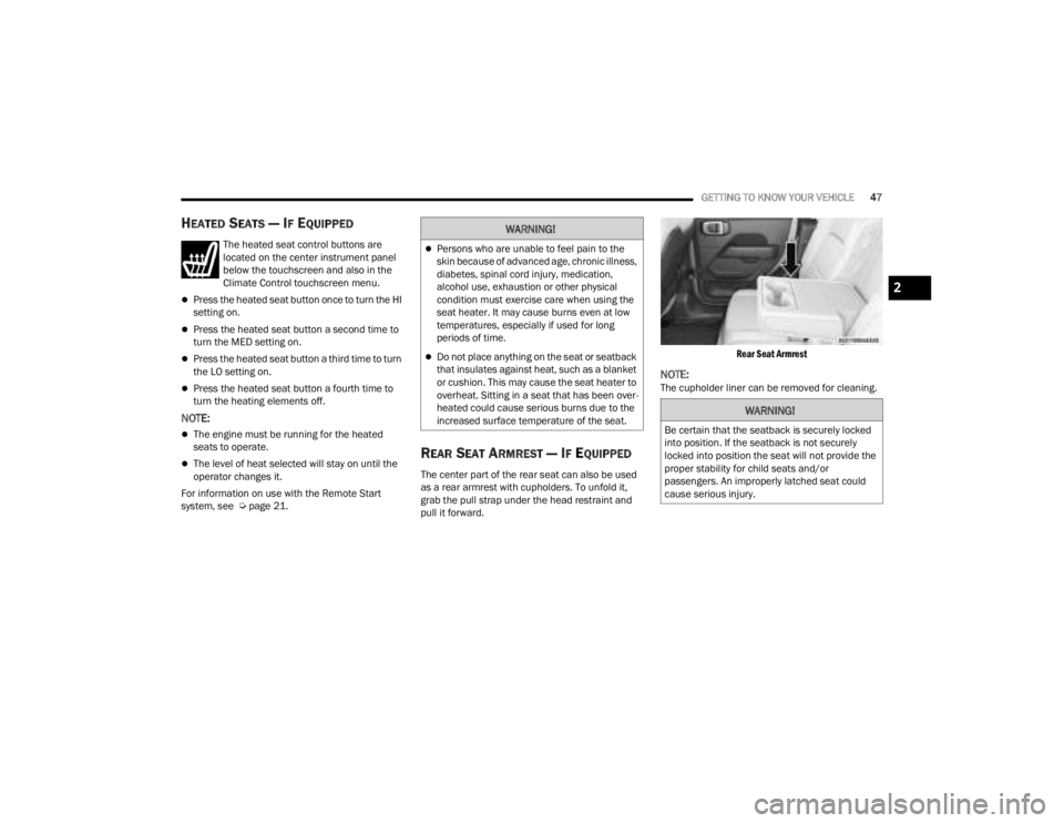
The center part of the rear seat can also be used
as a rear armrest with cupholders. To unfold it,
grab the pull strap under the head restraint and
pull it forward.
Rear Seat Armrest
NOTE:The cupholder liner can be removed for cleaning.
WARNING!
Persons who are unable to feel pain to the
skin because of advanced age, chronic illness,
diabetes, spinal cord injury, medication,
alcohol use, exhaustion or other physical
condition must exercise care when using the
seat heater. It may cause burns even at low
temperatures, especially if used for long
periods of time.
Do not place anything on the seat or seatback
that insulates against heat, such as a blanket
or cushion. This may cause the seat heater to
overheat. Sitting in a seat that has been over
-
heated could cause serious burns due to the
increased surface temperature of the seat.
WARNING!
Be certain that the seatback is securely locked
into position. If the seatback is not securely
locked into position the seat will not provide the
proper stability for child seats and/or
passengers. An improperly latched seat could
cause serious injury.
2
23_JT_OM_EN_USC_t.book Page 47
Page 57 of 448

GETTING TO KNOW YOUR VEHICLE55
REPROGRAMMING A SINGLE
H
OMELINK® BUTTON
To reprogram a single HomeLink® button that has
been previously trained, without erasing all the
channels, proceed as follows. Be sure to
determine whether the new device you want to
program the HomeLink® button to has a rolling
code, or non-rolling code.
1. Place the ignition in the ON/RUN position,
without starting the engine.
2. Push and hold the desired HomeLink® button until the HomeLink® Indicator light begins to
flash after 20 seconds. Do not release the
button.
3. Without releasing the button , proceed with
Step 2 in “Programming HomeLink® To A
Garage Door Opener” and follow all remaining
steps.
CANADIAN/GATE OPERATOR
P
ROGRAMMING
For programming transmitters in Canada/United
States that require the transmitter signals to
“time-out” after several seconds of transmission,
see the following. Canadian Radio Frequency (RF) laws require
transmitter signals to time-out (or quit) after
several seconds of transmission – which may not
be long enough for HomeLink® to pick up the
signal during programming. Similar to this
Canadian law, some US gate operators are
designed to time-out in the same manner.
It may be helpful to unplug the device during the
cycling process to prevent possible overheating of
the garage door or gate motor.
1. Place the ignition in the ON/RUN position.
2. Place the hand-held transmitter 1 to 3 inches
(3 to 8 cm) away from the HomeLink® button
you wish to program while keeping the
HomeLink® indicator light in view.
3. Continue to press and hold the HomeLink® button, while you press and release (cycle)
your hand-held transmitter every two seconds
until HomeLink® has successfully accepted
the frequency signal. The indicator light will
flash slowly and then rapidly when fully
trained.
4. Watch for the HomeLink® indicator to change flash rates. When it changes, it is
programmed. It may take up to 30 seconds or
longer in rare cases. The garage door may
open and close while you are programming. 5. Press and hold the programmed HomeLink®
button and observe the indicator light.
NOTE:
If the indicator light stays on constantly,
programming is complete and the garage
door/device should activate when the
HomeLink® button is pressed.
To program the two remaining HomeLink®
buttons, repeat each step for each
remaining button. DO NOT erase the chan -
nels.
If you unplugged the garage door opener/device
for programming, plug it back in at this time.
Reprogramming A Single HomeLink® Button
(Canadian/Gate Operator)
To reprogram a channel that has been previously
trained, follow these steps:
1. Place the ignition in the ON/RUN position.
2. Press and hold the desired HomeLink® button until the indicator light begins to flash after
20 seconds. Do not release the button.
3. Without releasing the button, proceed with “Canadian/Gate Operator Programming”
step 2 and follow all remaining steps.
2
23_JT_OM_EN_USC_t.book Page 55
Page 69 of 448

GETTING TO KNOW YOUR VEHICLE67
AUTOMATIC TEMPERATURE CONTROL
(ATC) — I
F EQUIPPED
Automatic Operation
1. Push the AUTO button on the faceplate, or the
AUTO button on the touchscreen on the
Automatic Temperature Control (ATC) Panel.
2. Next, adjust the temperature that you would like the system to maintain by adjusting the
driver and passenger temperature control
buttons. Once the desired temperature is
displayed, the system will achieve and
automatically maintain that comfort level.
3. When the system is set up for your comfort level, it is not necessary to change the
settings. You will experience the greatest
efficiency by simply allowing the system to
function automatically.
NOTE:
It is not necessary to move the temperature
settings for cold or hot vehicles. The system
automatically adjusts the temperature, mode,
and blower speed to provide comfort as quickly
as possible.
The temperature can be displayed in U.S. or
Metric units by selecting the U.S./Metric
customer-programmable feature within
Uconnect Settings Ú page 215. To provide you with maximum comfort in the
Automatic mode during cold start-ups, the blower
fan will remain on low until the engine warms up.
The blower will increase in speed and transition
into Auto mode.
Manual Operation Override
This system offers a full complement of manual
override features. The AUTO symbol in the front
ATC display will be turned off when the system is
being used in the manual mode.
CLIMATE VOICE COMMANDS
Adjust vehicle temperatures hands-free and keep
everyone comfortable while you keep moving
ahead.
Push the VR button on the steering wheel. After the
beep, say one of the following commands:
“
Set the driver temperature to 70 degrees ”
“Set the passenger temperature to 70 degrees ”
Did You Know:
Voice Command for Climate may
only be used to adjust the interior temperature of
your vehicle. Voice Command will not work to adjust
the heated seats or steering wheel if equipped.
OPERATING TIPS
NOTE:Refer to the chart at the end of this section for
suggested control settings for various weather
conditions.
Summer Operation
The engine cooling system must be protected with
a high-quality antifreeze coolant to provide proper
corrosion protection and to protect against engine
overheating. OAT coolant (conforming to
MS.90032) is recommended.
Winter Operation
To ensure the best possible heater and defroster
performance, make sure the engine cooling
system is functioning properly and the proper
amount, type, and concentration of coolant is
used. Use of the Air Recirculation mode during
Winter months is not recommended, because it
may cause window fogging.
Vacation/Storage
For information on maintaining the Climate Control
system when the vehicle is being stored for an
extended period of time, see Ú page 411.
2
23_JT_OM_EN_USC_t.book Page 67
Page 120 of 448
118GETTING TO KNOW YOUR INSTRUMENT PANEL
Use this QR code to access your
digital experience.
INSTRUMENT CLUSTER
D
ESCRIPTIONS
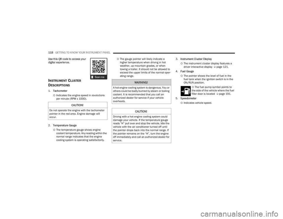
1.
Tachometer
Indicates the engine speed in revolutions
per minute (RPM x 1000).
2. Temperature Gauge
The temperature gauge shows engine
coolant temperature. Any reading within the
normal range indicates that the engine
cooling system is operating satisfactorily.
The gauge pointer will likely indicate a
higher temperature when driving in hot
weather, up mountain grades, or when
towing a trailer. It should not be allowed to
exceed the upper limits of the normal oper -
ating range. 3.
Instrument Cluster Display
The instrument cluster display features a
driver interactive display Ú page 121.
4. Fuel Gauge
The pointer shows the level of fuel in the
fuel tank when the ignition switch is in the
ON/RUN position.
The fuel pump symbol points to
the side of the vehicle where the fuel
filler door is located Ú page 191.
5. Speedometer
Indicates vehicle speed.CAUTION!
Do not operate the engine with the tachometer
pointer in the red area. Engine damage will
occur.
WARNING!
A hot engine cooling system is dangerous. You or
others could be badly burned by steam or boiling
coolant. It is recommended that you call an
authorized dealer for service if your vehicle
overheats.
CAUTION!
Driving with a hot engine cooling system could
damage your vehicle. If the temperature gauge
reads “H” pull over and stop the vehicle. Idle the
vehicle with the air conditioner turned off until
the pointer drops back into the normal range. If
the pointer remains on the “H”, turn the engine
off immediately and call an authorized dealer for
service.
23_JT_OM_EN_USC_t.book Page 118
Page 123 of 448
GETTING TO KNOW YOUR INSTRUMENT PANEL121
INSTRUMENT CLUSTER DESCRIPTIONS
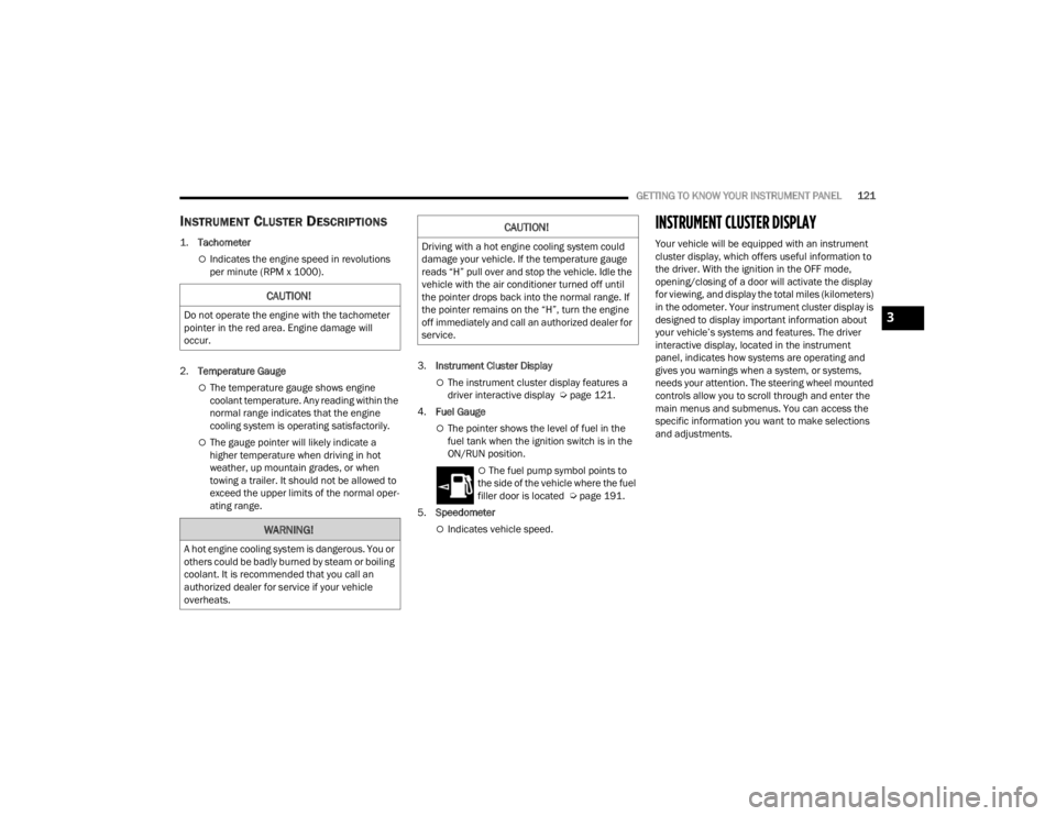
1.
Tachometer
Indicates the engine speed in revolutions
per minute (RPM x 1000).
2. Temperature Gauge
The temperature gauge shows engine
coolant temperature. Any reading within the
normal range indicates that the engine
cooling system is operating satisfactorily.
The gauge pointer will likely indicate a
higher temperature when driving in hot
weather, up mountain grades, or when
towing a trailer. It should not be allowed to
exceed the upper limits of the normal oper -
ating range. 3.
Instrument Cluster Display
The instrument cluster display features a
driver interactive display Ú page 121.
4. Fuel Gauge
The pointer shows the level of fuel in the
fuel tank when the ignition switch is in the
ON/RUN position.
The fuel pump symbol points to
the side of the vehicle where the fuel
filler door is located Ú page 191.
5. Speedometer
Indicates vehicle speed.
INSTRUMENT CLUSTER DISPLAY
Your vehicle will be equipped with an instrument
cluster display, which offers useful information to
the driver. With the ignition in the OFF mode,
opening/closing of a door will activate the display
for viewing, and display the total miles (kilometers)
in the odometer. Your instrument cluster display is
designed to display important information about
your vehicle’s systems and features. The driver
interactive display, located in the instrument
panel, indicates how systems are operating and
gives you warnings when a system, or systems,
needs your attention. The steering wheel mounted
controls allow you to scroll through and enter the
main menus and submenus. You can access the
specific information you want to make selections
and adjustments.
CAUTION!
Do not operate the engine with the tachometer
pointer in the red area. Engine damage will
occur.
WARNING!
A hot engine cooling system is dangerous. You or
others could be badly burned by steam or boiling
coolant. It is recommended that you call an
authorized dealer for service if your vehicle
overheats.
CAUTION!
Driving with a hot engine cooling system could
damage your vehicle. If the temperature gauge
reads “H” pull over and stop the vehicle. Idle the
vehicle with the air conditioner turned off until
the pointer drops back into the normal range. If
the pointer remains on the “H”, turn the engine
off immediately and call an authorized dealer for
service.
3
23_JT_OM_EN_USC_t.book Page 121
Page 135 of 448
GETTING TO KNOW YOUR INSTRUMENT PANEL133
The light also will turn on when the parking brake
is applied with the ignition switch in the ON/RUN
position.
NOTE:This light shows only that the parking brake is
applied. It does not show the degree of brake appli -
cation.
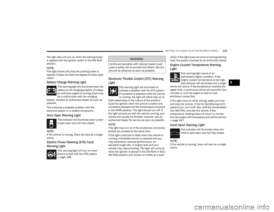
Battery Charge Warning Light
This warning light will illuminate when the
battery is not charging properly. If it stays
on while the engine is running, there may
be a malfunction with the charging
system. Contact an authorized dealer as soon as
possible.
This indicates a possible problem with the
electrical system or a related component.
Door Open Warning Light
This indicator will illuminate when a door
is ajar/open and not fully closed.
NOTE:If the vehicle is moving, there will also be a single
chime.
Electric Power Steering (EPS) Fault
Warning Light
This warning light will turn on when
there's a fault with the EPS system
Ú page 168.
Electronic Throttle Control (ETC) Warning
Light
This warning light will illuminate to
indicate a problem with the ETC system.
If a problem is detected while the vehicle
is running, the light will either stay on or
flash depending on the nature of the problem.
Cycle the ignition when the vehicle is safely and
completely stopped and the transmission is placed
in the PARK position. The light should turn off. If
the light remains on with the vehicle running, your
vehicle will usually be drivable; however, see an
authorized dealer for service as soon as possible.
NOTE:This light may turn on if the accelerator and brake
pedals are pressed at the same time.
If the light continues to flash when the vehicle is
running, immediate service is required and you
may experience reduced performance, an
elevated/rough idle, or engine stall and your
vehicle may require towing. The light will come on
when the ignition is placed in the ON/RUN or ACC/
ON/RUN position and remain on briefly as a bulb check. If the light does not come on during starting,
have the system checked by an authorized dealer.
Engine Coolant Temperature Warning
Light
This warning light warns of an
overheated engine condition. If the
engine coolant temperature is too high,
this indicator will illuminate and a single
chime will sound. If the temperature reaches the
upper limit, a continuous chime will sound for four
minutes or until the engine is able to cool;
whichever comes first.
If the light turns on while driving, safely pull over
and stop the vehicle. If the Air Conditioning (A/C)
system is on, turn it off. Also, shift the transmission
into NEUTRAL and idle the vehicle. If the
temperature reading does not return to normal,
turn the engine off immediately and call for service
Ú page 347.
Hood Open Warning Light
This indicator will illuminate when the
hood is ajar/open and not fully closed.
NOTE:If the vehicle is moving, there will also be a single
chime.
WARNING!
Continued operation with reduced assist could
pose a safety risk to yourself and others. Service
should be obtained as soon as possible.
3
23_JT_OM_EN_USC_t.book Page 133
Page 137 of 448
GETTING TO KNOW YOUR INSTRUMENT PANEL135
Vehicle Security Warning Light —
If Equipped
This light will flash at a fast rate for
approximately 15 seconds when the
vehicle security system is arming, and
then will flash slowly until the vehicle is
disarmed.
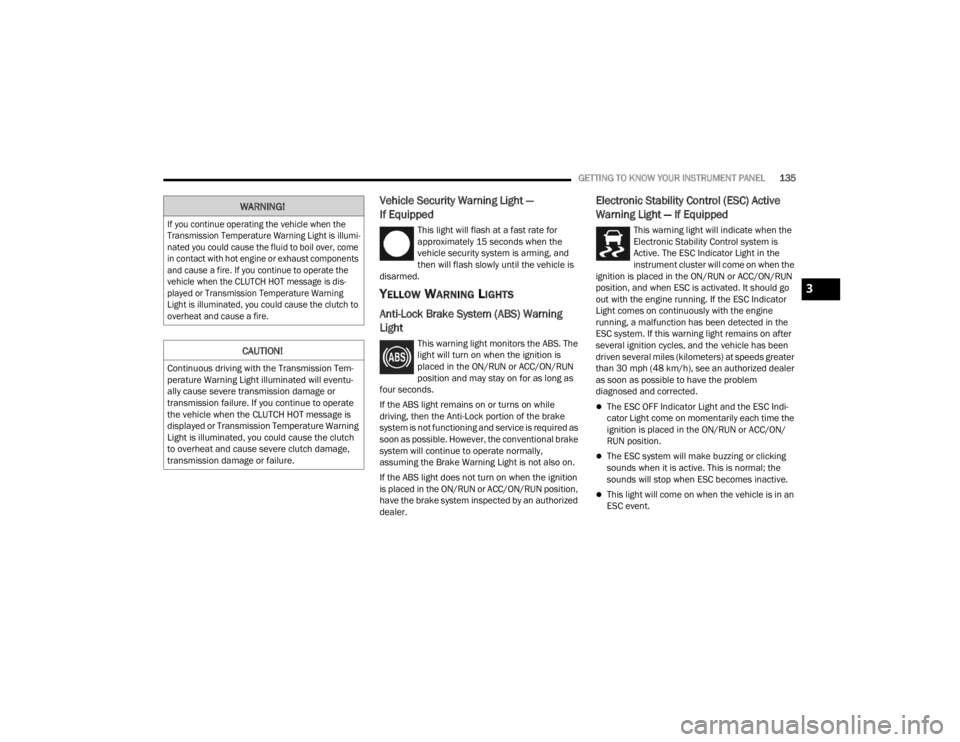
YELLOW WARNING LIGHTS
Anti-Lock Brake System (ABS) Warning
Light
This warning light monitors the ABS. The
light will turn on when the ignition is
placed in the ON/RUN or ACC/ON/RUN
position and may stay on for as long as
four seconds.
If the ABS light remains on or turns on while
driving, then the Anti-Lock portion of the brake
system is not functioning and service is required as
soon as possible. However, the conventional brake
system will continue to operate normally,
assuming the Brake Warning Light is not also on.
If the ABS light does not turn on when the ignition
is placed in the ON/RUN or ACC/ON/RUN position,
have the brake system inspected by an authorized
dealer.
Electronic Stability Control (ESC) Active
Warning Light — If Equipped
This warning light will indicate when the
Electronic Stability Control system is
Active. The ESC Indicator Light in the
instrument cluster will come on when the
ignition is placed in the ON/RUN or ACC/ON/RUN
position, and when ESC is activated. It should go
out with the engine running. If the ESC Indicator
Light comes on continuously with the engine
running, a malfunction has been detected in the
ESC system. If this warning light remains on after
several ignition cycles, and the vehicle has been
driven several miles (kilometers) at speeds greater
than 30 mph (48 km/h), see an authorized dealer
as soon as possible to have the problem
diagnosed and corrected.
The ESC OFF Indicator Light and the ESC Indi -
cator Light come on momentarily each time the
ignition is placed in the ON/RUN or ACC/ON/
RUN position.
The ESC system will make buzzing or clicking
sounds when it is active. This is normal; the
sounds will stop when ESC becomes inactive.
This light will come on when the vehicle is in an
ESC event.
WARNING!
If you continue operating the vehicle when the
Transmission Temperature Warning Light is illumi -
nated you could cause the fluid to boil over, come
in contact with hot engine or exhaust components
and cause a fire. If you continue to operate the
vehicle when the CLUTCH HOT message is dis -
played or Transmission Temperature Warning
Light is illuminated, you could cause the clutch to
overheat and cause a fire.
CAUTION!
Continuous driving with the Transmission Tem -
perature Warning Light illuminated will eventu -
ally cause severe transmission damage or
transmission failure. If you continue to operate
the vehicle when the CLUTCH HOT message is
displayed or Transmission Temperature Warning
Light is illuminated, you could cause the clutch
to overheat and cause severe clutch damage,
transmission damage or failure.
3
23_JT_OM_EN_USC_t.book Page 135
Page 149 of 448
STARTING AND OPERATING147
(Continued)
2. Press and hold the brake pedal while pushing
the ENGINE START/STOP button once.
3. If the engine fails to start within 10 seconds, place the ignition in the OFF position, wait
10 to 15 seconds to allow the starter to cool,
then repeat the “Extended Park Starting”
procedure.
4. If the engine fails to start after eight attempts, allow the starter to cool for at least
10 minutes, then repeat the procedure.
IF ENGINE FAILS TO START
If the engine fails to start after you have followed
the “Normal Starting” procedure and the vehicle
has not experienced an extended park condition
as defined previously, it may be flooded. Push the
accelerator pedal all the way to the floor and hold
it there. Crank the engine for no more than 10
seconds. This should clear any excess fuel in case
the engine is flooded. Leave the ignition key in the
ON/ RUN position, release the accelerator pedal
and repeat the “Normal Starting” procedure.
AFTER STARTING
The idle speed is controlled automatically and will
decrease as the engine warms up.
STARTING THE ENGINE — DIESEL ENGINE
(IF EQUIPPED)
Before starting your vehicle, adjust your seat, both
inside and outside mirrors, and fasten your seat
belts.
The starter is allowed to crank for up to 25-second
intervals. Waiting two minutes between such
intervals will protect the starter from overheating.
CAUTION!
To prevent damage to the starter, do not crank
continuously for more than 10 seconds at a
time. Wait 10 to 15 seconds before trying again.
WARNING!
Never pour fuel or other flammable liquid into
the throttle body air inlet opening in an
attempt to start the vehicle. This could result
in flash fire causing serious personal injury.
Do not attempt to push or tow your vehicle to
get it started. Vehicles equipped with an auto -
matic transmission cannot be started this
way. Unburned fuel could enter the catalytic
converter and once the engine has started,
ignite and damage the converter and vehicle.
If the vehicle has a discharged battery,
booster cables may be used to obtain a start
from a booster battery or the battery in
another vehicle. This type of start can be
dangerous if done improperly Ú page 343.
CAUTION!
To prevent damage to the starter, do not
continuously crank the engine for more than
10 seconds at a time. Wait 10 to 15 seconds
before trying again.
WARNING!
Before exiting a vehicle, always come to a
complete stop, then shift the automatic trans -
mission into PARK and apply the parking
brake.
Always make sure the keyless ignition node is
in the OFF position, key fob is removed from
the vehicle and vehicle is locked.
Never leave children alone in a vehicle, or with
access to an unlocked vehicle. Leaving chil -
dren in a vehicle unattended is dangerous for
a number of reasons. A child or others could
be seriously or fatally injured. Children should
be warned not to touch the parking brake,
brake pedal or the gear selector.
4
23_JT_OM_EN_USC_t.book Page 147
Page 153 of 448

STARTING AND OPERATING151
NOTE:Under certain conditions the Stop/Start system
may be temporarily disabled and the engine fan
will run after the engine is turned off to protect the
engine. These conditions are under high load and
high temperature conditions.
COOLING SYSTEM TIPS — AUTOMATIC
T
RANSMISSION
To reduce the potential for engine and
transmission overheating in high ambient
temperature conditions, take the following actions:
City Driving — When stopped, shift the transmis -
sion into NEUTRAL (N) and increase engine idle
speed.
Highway Driving — Reduce your speed.
Up Steep Hills — Select a lower transmission
gear.
Air Conditioning — Turn it off temporarily.
NOTE:If the coolant temperature is too high, the A/C will
automatically turn off.
Do Not Operate The Engine With Low Oil
Pressure
If the Low Oil Pressure Warning Light turns on while
driving, stop the vehicle and shut down the engine
as soon as possible. After the vehicle is safely
stopped, restart the engine and monitor the lamp. If the lamp is still illuminated, shut the engine off,
contact an authorized dealer, and do not operate
the vehicle until the cause is corrected. If the lamp
is no longer illuminated, the engine can be
operated, but should be taken to an authorized
dealer as soon as possible for further inspection.
NOTE:Do not operate the vehicle until the cause is
corrected. This light does not show how much oil is
in the engine. The engine oil level must be checked
under the hood.
Do Not Operate The Engine With Failed
Parts
All engine failures give some warning before the
parts fail. Be on the alert for changes in
performance, sounds, and visual evidence that the
engine requires service. Some important clues are:
Engine misfiring or vibrating severely
Sudden loss of power
Unusual engine noises
Fuel, oil or coolant leaks
Sudden change, outside the normal operating
range, in the engine operating temperature
Excessive smoke
Oil pressure drop
ENGINE BREAK-IN RECOMMENDATIONS —
GASOLINE ENGINE (IF EQUIPPED)
A long break-in period is not required for the engine
and drivetrain (transmission and axle) in your
vehicle.
Drive moderately during the first 300 miles
(500 km). After the initial 60 miles (100 km),
speeds up to 50 or 55 mph (80 or 90 km/h) are
desirable.
While cruising, brief full-throttle acceleration within
the limits of local traffic laws contributes to a good
break-in. Wide-open throttle acceleration in low
gear can be detrimental and should be avoided.
The engine oil installed in the engine at the factory
is a high-quality energy conserving type lubricant.
Oil changes should be consistent with anticipated
climate conditions under which vehicle operations
will occur.
For the recommended viscosity and quality grades
see Ú page 424.
CAUTION!
If oil pressure falls to less than normal readings,
shut the engine off immediately. Failure to do so
could result in immediate and severe engine
damage.
4
23_JT_OM_EN_USC_t.book Page 151