run flat JEEP GLADIATOR 2023 Owners Manual
[x] Cancel search | Manufacturer: JEEP, Model Year: 2023, Model line: GLADIATOR, Model: JEEP GLADIATOR 2023Pages: 448, PDF Size: 17.37 MB
Page 2 of 448

WARNING: Operating, servicing and maintaining a passenger vehicle or off-highway
motor vehicle can expose you to chemicals including engine exhaust, carbon monoxide,
phthalates, and lead, which are known to the State of California to cause cancer and
birth defects or other reproductive harm. To minimize exposure, avoid breathing exhaust,
do not idle the engine except as necessary, service your vehicle in a well-ventilated area
and wear gloves or wash your hands frequently when servicing your vehicle. For more
information go to www.P65Warnings.ca.gov/passenger-vehicle.
The driver’s primary responsibility is the safe operation of the vehicle. Driving while distracted can result in loss of vehicle control, resulting in an accident
and personal injury. FCA US LLC strongly recommends that the driver use extreme caution when using any device or feature that may take their attention
off the road. Use of any electrical devices, such as cellular telephones, computers, portable radios, vehicle navigation or other devices by the driver while
the vehicle is moving is dangerous and could lead to a serious accident. Texting while driving is also dangerous and should never be done while the vehicle
is moving. If you find yourself unable to devote your full attention to vehicle operation, pull off the road to a safe location and stop your vehicle. Some states
or provinces prohibit the use of cellular telephones or texting while driving. It is always the driver’s responsibility to comply with all local laws.
This Owner’s Manual has been prepared to help you get acquainted with your new Jeep
® brand vehicle and to provide a convenient reference source for
common questions.
Not all features shown in this manual may apply to your vehicle. For additional information, visit mopar.com/om (USA), owners.mopar.ca (Canada) or your
local Jeep
® brand dealer.
U.S. Residents: If you are the first registered retail owner of your vehicle, you may obtain a complimentary printed copy of the Warranty Booklet by calling
1-877-426-5337 or by contacting your dealer. Replacement kits can be purchased by visiting www.techauthority.com.
Canadian Residents: If you are the first registered retail owner of your vehicle, you may obtain a complimentary printed copy of the Warranty Booklet or
purchase a replacement kit by calling 1-800-387-1143 or by contacting your dealer.
DRIVING AND ALCOHOL
Drunk driving is one of the most frequent causes of accidents. Your driving ability can be seriously impaired with blood alcohol levels far below the legal
minimum. If you are drinking, don’t drive. Ride with a designated non-drinking driver, call a cab, a rideshare, a friend or use public transportation.
WARNING
Driving after drinking can lead to an accident. Your perceptions are less sharp, your reflexes are slower and your judgment is impaired when you have been
drinking. Never drink and then drive.
This Owner’s Manual illustrates and describes the operation of features and equipment that are either standard or optional on this vehicle. This manual may
also include a description of features and equipment that are no longer available or were not ordered on this vehicle. Please disregard any features and
equipment described in this manual that are not on this vehicle.
FCA US LLC reserves the right to make changes in design and specifications, and/or make
additions to or improvements to its products without imposing any obligation upon itself to install them on products previously manufactured.
With respect to any vehicles sold in Canada, the name FCA US LLC shall be deemed to be deleted and the name FCA Canada Inc. used in substitution
therefore.
This Owner’s Manual is intended to familiarize you with the important features of your vehicle. Your most up-to-date Owner’s Manual, Navigation/Uconnect
manuals and Warranty Booklet can be found by visiting the website on the back cover.
ROADSIDE ASSISTANCE
24 HOURS, 7 DAYS A WEEK AT YOUR SERVICE. CALL 1-800-521-2779 OR VISIT CHRYSLER.RSAHELP.COM (USA)
CALL 1-800-363-4869 OR VISIT FCA.ROADSIDEAID.COM (CANADA) SERVICES: Flat Tire Service, Out Of Gas/Fuel Delivery, Battery Jump Assistance, Lockout Service and Towing Service
Please see the Customer Assistance chapter in this Owner’s Manual for further information.
FCA US LLC reserves the right to modify the terms or discontinue the Roadside Assistance Program at any time. The Roadside Assistance Program is subject to restrictions and
conditions of use, that are determined solely by FCA US LLC.
Page 18 of 448
16GETTING TO KNOW YOUR VEHICLE
To Lock/Unlock The Doors And Tailgate
Push and release the unlock button on the key fob
once to unlock the driver’s door, or twice to unlock
all the doors. To lock all the doors, push the lock
button once.
When the doors are unlocked, the turn signals will
flash and the illuminated entry system will be
activated. When the doors are locked, the turn
signals will flash and the horn will chirp.
NOTE:
All doors can be programmed to unlock on the
first push of the unlock button through
Uconnect Settings Úpage 215.
The mechanical flip key can be used to lock or
unlock the doors, tailgate, glove compartment,
storage compartments (if equipped), and rear
seatbacks.
Key Left Vehicle Feature
If a valid key fob is no longer detected inside the
vehicle while the vehicle’s ignition system is in the
ON/RUN or START position, the message “Key Fob
Has Left The Vehicle” will be shown in the
instrument cluster display along with an interior
chime. An exterior audible and visual alert will also
be activated to warn the driver. The vehicle’s horn will rapidly chirp three times
along with a single flash of the vehicle’s exterior
lights.
NOTE:
The doors have to be open and then closed in
order for the vehicle to check for the presence of
a key fob; the Key Left Vehicle feature will not
activate until all of the doors are closed.
These alerts will not be activated in situations
where the vehicle’s engine is left running with
the key fob inside.
Replacing The Battery In The Key Fob
The recommended replacement battery is
CR2450.
NOTE:
Customers are recommended to use a battery
obtained from Mopar®. Aftermarket coin
battery dimensions may not meet the original
OEM coin battery dimensions.
Perchlorate material — special handling may
apply. See www.dtsc.ca.gov/hazardouswaste/
perchlorate for further information.
Do not touch the battery terminals that are on
the back housing or the printed circuit board.
When a key fob battery is low, a warning will be
indicated on the vehicle’s instrument cluster,
and the fob LED will no longer illuminate with a
button push.
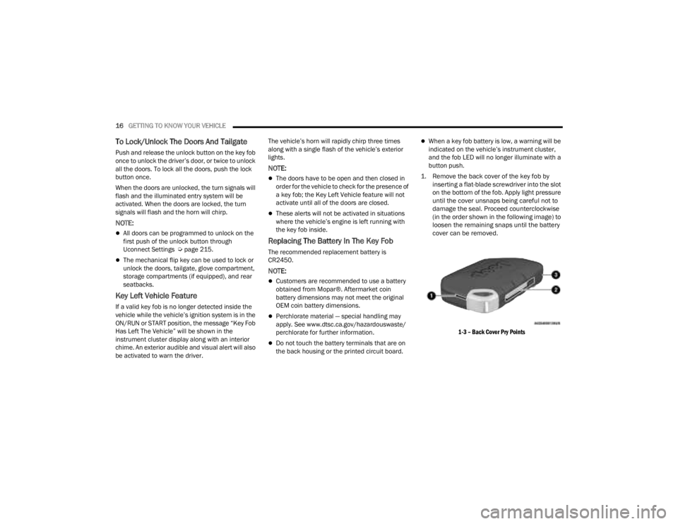
1. Remove the back cover of the key fob by inserting a flat-blade screwdriver into the slot
on the bottom of the fob. Apply light pressure
until the cover unsnaps being careful not to
damage the seal. Proceed counterclockwise
(in the order shown in the following image) to
loosen the remaining snaps until the battery
cover can be removed.
1-3 – Back Cover Pry Points
23_JT_OM_EN_USC_t.book Page 16
Page 206 of 448
204STARTING AND OPERATING
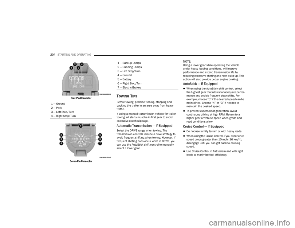
Four-Pin Connector
Seven-Pin Connector
TOWING TIPS
Before towing, practice turning, stopping and
backing the trailer in an area away from heavy
traffic.
If using a manual transmission vehicle for trailer
towing, all starts must be in first gear to avoid
excessive clutch slippage.
Automatic Transmission — If Equipped
Select the DRIVE range when towing. The
transmission controls include a drive strategy to
avoid frequent shifting when towing. However, if
frequent shifting does occur while in DRIVE, you
can use the AutoStick shift control to manually
select a lower gear.
NOTE:Using a lower gear while operating the vehicle
under heavy loading conditions, will improve
performance and extend transmission life by
reducing excessive shifting and heat build-up. This
action will also provide better engine braking.
AutoStick — If Equipped
When using the AutoStick shift control, select
the highest gear that allows for adequate perfor -
mance and avoids frequent downshifts. For
example, choose “5” if the desired speed can be
maintained. Choose “4” or “3” if needed to
maintain the desired speed.
To prevent excess heat generation, avoid
continuous driving at high RPM. Return to a
higher gear or vehicle speed when grade and
road conditions allow.
Cruise Control — If Equipped
Do not use in hilly terrain or with heavy loads.
When using the Cruise Control, if you experience
speed drops greater than 10 mph (16 km/h),
disengage until you can get back to cruising
speed.
Use Cruise Control in flat terrain and with light
loads to maximize fuel efficiency.
1 — Ground
2 — Park
3 — Left Stop/Turn
4 — Right Stop/Turn
1 — Backup Lamps
2 — Running Lamps
3 — Left Stop/Turn
4 — Ground
5 — Battery
6 — Right Stop/Turn
7 — Electric Brakes
23_JT_OM_EN_USC_t.book Page 204
Page 268 of 448
266MULTIMEDIA
The doors, hood, and trunk/liftgate are closed.
The vehicle’s check engine light must be off.
The vehicle must have at least a quarter tank of
fuel, along with oil and battery power.
The vehicle’s hazard lights must be off.
If equipped, the vehicle must have an automatic
transmission.
The vehicle must be in an open area with cell
tower reception.
Your mobile device must have a cellular or Wi-Fi
connection.
If the Panic button has been pressed, the
vehicle must be started at least once after
alarming the system.
NOTE:
The SiriusXM Guardian™ Customer Care agents are
not authorized for Remote Vehicle Start services.
Contact the Uconnect Care Team for assistance.
Remote Horn & Lights
Description
It is easy to locate a vehicle in a dark, crowded or
noisy parking area by activating the horn and
lights. It may also help if you need to draw attention
to your vehicle for any reason.
If you want, you can set up push notifications every
time a command is sent to turn on the horn and
lights. Working Vehicle Conditions
The vehicle must in PARK or at a standstill.
The vehicle must be in an open area with cell
tower reception.
Your mobile device must have a cellular or Wi-Fi
connection.
NOTE:The Remote Horn & Lights feature is designed to
be loud and get noticed. Please keep in mind the
surroundings when using this feature. You are
responsible for compliance with local laws, rules
and ordinances in the location of your vehicle
when using Remote Horn & Lights.
Assist — If Equipped
Description
Vehicles equipped with the SiriusXM Guardian™
connected services feature may contain an ASSIST
button in the vehicle. Once your SiriusXM
Guardian™ connected services have been
activated, the ASSIST button can connect you
directly to the Customer Care call center (if
equipped). You will be directed to one of the
following four services:
Roadside Assistance
— If you get a flat tire or
need a tow, you’ll be connected to someone
who can help anytime.
Connected Services — Contact the SiriusXM
Guardian™ Customer Care call center to acti -vate your services, renew after your trial has
expired, for in-vehicle support for your SiriusXM
Guardian™ connected services, or help
answering any general questions surrounding
your connected services.
Uconnect Care — In-vehicle support for all
non-connected Uconnect system features, such
as radio and Bluetooth® connections.
Vehicle Care
— Total support for your vehicle.
SiriusXM Guardian™ In-Vehicle Assistance
Features — If Equipped
With SiriusXM Guardian™, your vehicle has
onboard assistance features located on the
rearview mirror or overhead console designed to
enhance your driving experience if you should ever
need assistance or support.
How It Works
Simply push the ASSIST button in the vehicle and
you will be presented with your ASSIST options on
the touchscreen. Make your selection by pressing
the touchscreen.
Requirements
This feature is available only on vehicles sold in
the US and Canada.
Vehicle must be properly equipped with the
SiriusXM Guardian™ connected services.
Vehicle must have an operable LTE (voice/data)
or 4G (data) network connection.
23_JT_OM_EN_USC_t.book Page 266
Page 299 of 448
SAFETY297
Vehicles With A Full-Size Matching Spare
1. If your vehicle is equipped with a matching full-size spare wheel and tire assembly, it has
a Tire Pressure Monitoring System sensor,
and can be monitored by the Tire Pressure
Monitoring System (TPMS) when swapped
with a low pressure road tire.
2. In the event that the matching full-size spare tire is swapped with a low pressure road tire,
the next ignition switch cycle will still show the
TPMS Warning Light to be on, a chime to
sound, an “Inflate to XX” message to appear in
the instrument cluster, and the graphic display
will still show the low tire pressure value in a
different color.
3. Driving the vehicle for up to 20 minutes above 15 mph (24 km/h) will turn off the TPMS
Warning Light as long as none of road tires are
below the low pressure warning threshold.
TIRE FILL ALERT
This feature notifies the user when the placard tire
pressure is attained while inflating or deflating the
tire.
The customer may choose to disable or enable the
Tire Fill Alert feature in the apps menu of the
Uconnect system.
NOTE:
Only one tire can be filled at a time when using
the Tire Fill Alert system.
The Tire Fill Alert feature cannot be entered if an
existing TPMS system fault is set to “active” or if
the system is in deactivation mode (if equipped).
The system will be activated when the system
detects an increase in tire pressure while filling the
tire. The ignition must be in the ON/RUN mode with
the transmission in PARK for vehicles equipped
with an automatic transmission. For vehicles
equipped with a manual transmission, the parking
brake must be applied.
NOTE:It is not required to have the engine running to
enter Tire Fill Alert mode.
The hazard lamps will come on to confirm the
vehicle is in Tire Fill Alert mode. If the hazard lamps
do not come on while inflating the tire, the Tire
Pressure Monitoring System (TPMS) sensor may
be in an inoperative position, preventing the TPMS
sensor signal from being received. In this case, the
vehicle may need to be moved slightly forward or
backward. The Tire Fill Alert system will only inflate or deflate
one tire at a time. Wait until the hazard lights have
stopped flashing for 30 seconds after the desired
pressure is achieved in one tire before switching to
another.
When Tire Fill Alert mode is entered, the tire
pressure display screen will be displayed in the
instrument cluster.
Operation:
The horn will chirp once to let the user know
when to stop filling the tire, when it reaches
recommended pressure.
The horn will chirp three times if the tire is over
-
filled and will continue to chirp every five
seconds if the user continues to inflate the tire.
The horn will chirp once again when enough air
is let out to reach proper inflation level.
The horn will also chirp three times if the tire is
then underinflated and will continue to chirp
every five seconds if the user continues to
deflate the tire.
NOTE:The Tire Fill Alert feature is set to “Disabled” every
time the ignition is turned to “OFF”. To re-enable
the Tire Fill Alert feature at the next ignition “RUN”
state, the customer must re-enable the feature
through use of the customer settings in the radio.
6
23_JT_OM_EN_USC_t.book Page 297
Page 300 of 448
298SAFETY
SELECTABLE TIRE FILL ALERT — IF EQUIPPED
The Selectable Tire Fill Alert (STFA) system is an
optional feature that is included as part of the
normal Tire Fill Alert system. The system is
designed to allow you to select a pressure to inflate
or deflate the vehicle's front and rear axle tires to,
and to provide feedback while inflating or deflating
the vehicle's tires.
In the Selectable Tire Fill Alert application, which is
located in the apps menu of the Uconnect system,
you will be able to select a pressure setting for both
the front and rear axle tire pressures by scrolling
through a pressure range from XX to 15 psi in 1 psi
increments for each axle setting.
XX = the vehicle's cold placard pressure values for
the front and rear axles as shown on the vehicle
placard pressure label.
NOTE:The Tire Fill Alert feature disables every time the
ignition is placed in the OFF position. The feature
must be re-enabled through the radio each time
the ignition is placed back in the ON/RUN position
Úpage 215.
You may also store pressure values chosen for
each axle in the Uconnect system application as
preset pressure values. Up to two sets of preset
pressure values can be stored in the Uconnect
system for the front and rear axle. Once you select
the tire pressures for the front and rear axles that you want to inflate or deflate to, you can begin
inflating or deflating one tire at a time.
NOTE:The STFA system will only support inflating or
deflating one tire at a time.
In order to use STFA, the Tire Fill Alert feature must
be enabled through the radio Ú
page 215.
The system will be activated when the TPMS
receiver module detects a change in tire pressure.
The ignition must be in the ON/RUN mode, with the
transmission in PARK in vehicles with an automatic
transmission, and in NEUTRAL with the parking
brake engaged in vehicles with a manual
transmission. The hazard lamps will come on to
confirm the vehicle is in Tire Fill Alert mode.
When Tire Fill Alert mode is entered, the tire
pressure screen will be displayed in the instrument
cluster. If the hazard lamps do not come on while
inflating or deflating the tire, the Tire Pressure
Monitoring System (TPMS) sensor may be in an
inoperative position, preventing the TPMS sensor
signal from being received. In this case, the vehicle
may need to be moved slightly forward or
backward.
The STFA system will only inflate or deflate one tire
at a time. Wait until the hazard lights have stopped
flashing for 30 seconds after the desired pressure
is achieved on one tire before switching to another. Horn chirps will indicate STFA status as tires are
inflated/deflated. The horn will chirp under the
following STFA states:
1. The horn will chirp once when the selected
pressure is reached to let you know when to
stop inflating or deflating the tire.
2. The horn will chirp three times if the tire is overinflated or over-deflated.
3. The horn will chirp once again when enough air is added or removed to reach proper selected
pressure level.
TPMS DEACTIVATION — IF EQUIPPED
The TPMS can be deactivated if replacing all four
wheel and tire assemblies (road tires) with wheel
and tire assemblies that do not have TPMS
sensors, such as when installing winter wheel and
tire assemblies on your vehicle.
To deactivate the TPMS, first replace all four wheel
and tire assemblies (road tires) with tires not
equipped with Tire Pressure Monitoring System
(TPMS) sensors. Then, drive the vehicle for
20 minutes above 15 mph (24 km/h). The TPMS
will chime, the TPMS Warning Light will flash on
and off for 75 seconds and then remain on. The
instrument cluster will display the “SERVICE TIRE
PRESSURE SYSTEM” message and then display
dashes (--) in place of the pressure values.
23_JT_OM_EN_USC_t.book Page 298
Page 302 of 448
300SAFETY
SEAT BELT SYSTEMS
Buckle up even though you are an excellent driver,
even on short trips. Someone on the road may be
a poor driver and could cause a collision that
includes you. This can happen far away from home
or on your own street.
Research has shown that seat belts save lives, and
they can reduce the seriousness of injuries in a
collision. Some of the worst injuries happen when
people are thrown from the vehicle. Seat belts
reduce the possibility of ejection and the risk of
injury caused by striking the inside of the vehicle.
Everyone in a motor vehicle should be belted at all
times.
Enhanced Seat Belt Use Reminder System
(BeltAlert)
Driver And Passenger BeltAlert — If Equipped
BeltAlert is a feature intended to remind
the driver and outboard front seat
passenger (if equipped with outboard
front passenger seat BeltAlert) to buckle
their seat belts. The Belt Alert feature is active
whenever the ignition switch is in the START or ON/
RUN position.
Initial Indication
If the driver is unbuckled when the ignition switch
is first in the START or ON/RUN position, a chime
will signal for a few seconds. If the driver or outboard front seat passenger (if equipped with
outboard front passenger seat BeltAlert) is
unbuckled when the ignition switch is first in the
START or ON/RUN position the Seat Belt Reminder
Light will turn on and remain on until both outboard
front seat belts are buckled. The outboard front
passenger seat BeltAlert is not active when an
outboard front passenger seat is unoccupied.
BeltAlert Warning Sequence
The BeltAlert warning sequence is activated when
the vehicle is moving above a specified vehicle
speed range and the driver or outboard front seat
passenger is unbuckled (if equipped with outboard
front passenger seat BeltAlert) (the outboard front
passenger seat BeltAlert is not active when the
outboard front passenger seat is unoccupied). The
BeltAlert warning sequence starts by blinking the
Seat Belt Reminder Light and sounding an
intermittent chime. Once the BeltAlert warning
sequence has completed, the Seat Belt Reminder
Light will remain on until the seat belts are
buckled. The BeltAlert warning sequence may
repeat based on vehicle speed until the driver and
occupied outboard front seat passenger seat belts
are buckled. The driver should instruct all
occupants to buckle their seat belts.
Change Of Status
If the driver or outboard front seat passenger (if
equipped with outboard front passenger seat
BeltAlert) unbuckles their seat belt while the vehicle is traveling, the BeltAlert warning sequence
will begin until the seat belts are buckled again.
The outboard front passenger seat BeltAlert is not
active when the outboard front passenger seat is
unoccupied. BeltAlert may be triggered when an
animal or other items are placed on the outboard
front passenger seat or when the seat is folded flat
(if equipped). It is recommended that pets be
restrained in the rear seat (if equipped) in pet
harnesses or pet carriers that are secured by seat
belts, and cargo is properly stowed.
BeltAlert can be activated or deactivated by an
authorized dealer. FCA US LLC does not
recommend deactivating BeltAlert.
NOTE:If BeltAlert has been deactivated and the driver or
outboard front seat passenger (if equipped with
outboard front passenger seat BeltAlert) is
unbuckled the Seat Belt Reminder Light will turn
on and remain on until the driver and outboard
front seat passenger seat belts are buckled.
Lap/Shoulder Belts
All seating positions in your vehicle are equipped
with lap/shoulder belts.
The seat belt webbing retractor will lock only during
very sudden stops or collisions. This feature allows
the shoulder part of the seat belt to move freely
with you under normal conditions. However, in a
23_JT_OM_EN_USC_t.book Page 300
Page 308 of 448
306SAFETY
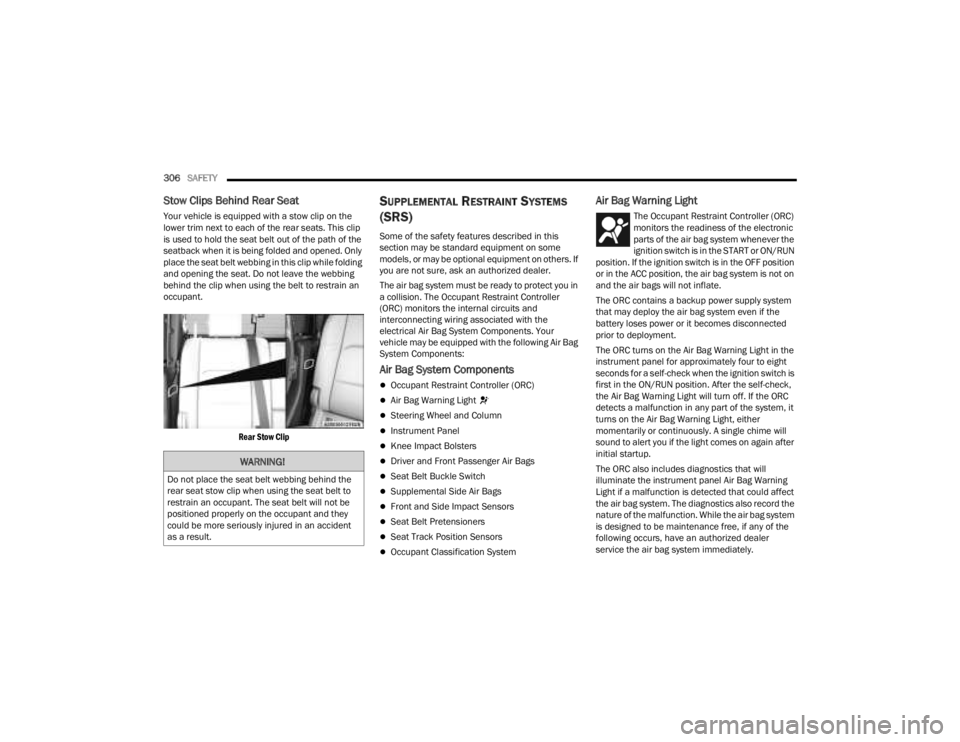
Stow Clips Behind Rear Seat
Your vehicle is equipped with a stow clip on the
lower trim next to each of the rear seats. This clip
is used to hold the seat belt out of the path of the
seatback when it is being folded and opened. Only
place the seat belt webbing in this clip while folding
and opening the seat. Do not leave the webbing
behind the clip when using the belt to restrain an
occupant.
Rear Stow Clip
SUPPLEMENTAL RESTRAINT SYSTEMS
(SRS)
Some of the safety features described in this
section may be standard equipment on some
models, or may be optional equipment on others. If
you are not sure, ask an authorized dealer.
The air bag system must be ready to protect you in
a collision. The Occupant Restraint Controller
(ORC) monitors the internal circuits and
interconnecting wiring associated with the
electrical Air Bag System Components. Your
vehicle may be equipped with the following Air Bag
System Components:
Air Bag System Components
Occupant Restraint Controller (ORC)
Air Bag Warning Light
Steering Wheel and Column
Instrument Panel
Knee Impact Bolsters
Driver and Front Passenger Air Bags
Seat Belt Buckle Switch
Supplemental Side Air Bags
Front and Side Impact Sensors
Seat Belt Pretensioners
Seat Track Position Sensors
Occupant Classification System
Air Bag Warning Light
The Occupant Restraint Controller (ORC)
monitors the readiness of the electronic
parts of the air bag system whenever the
ignition switch is in the START or ON/RUN
position. If the ignition switch is in the OFF position
or in the ACC position, the air bag system is not on
and the air bags will not inflate.
The ORC contains a backup power supply system
that may deploy the air bag system even if the
battery loses power or it becomes disconnected
prior to deployment.
The ORC turns on the Air Bag Warning Light in the
instrument panel for approximately four to eight
seconds for a self-check when the ignition switch is
first in the ON/RUN position. After the self-check,
the Air Bag Warning Light will turn off. If the ORC
detects a malfunction in any part of the system, it
turns on the Air Bag Warning Light, either
momentarily or continuously. A single chime will
sound to alert you if the light comes on again after
initial startup.
The ORC also includes diagnostics that will
illuminate the instrument panel Air Bag Warning
Light if a malfunction is detected that could affect
the air bag system. The diagnostics also record the
nature of the malfunction. While the air bag system
is designed to be maintenance free, if any of the
following occurs, have an authorized dealer
service the air bag system immediately.
WARNING!
Do not place the seat belt webbing behind the
rear seat stow clip when using the seat belt to
restrain an occupant. The seat belt will not be
positioned properly on the occupant and they
could be more seriously injured in an accident
as a result.
23_JT_OM_EN_USC_t.book Page 306
Page 309 of 448
SAFETY307
(Continued)
The Air Bag Warning Light does not come on
during the four to eight seconds when the igni -
tion switch is first in the ON/RUN position.
The Air Bag Warning Light remains on after the
four to eight-second interval.
The Air Bag Warning Light comes on intermit -
tently or remains on while driving.
NOTE:If the speedometer, tachometer, or any engine
related gauges are not working, the Occupant
Restraint Controller (ORC) may also be disabled. In
this condition the air bags may not be ready to
inflate for your protection. Have an authorized
dealer service the air bag system immediately.
Redundant Air Bag Warning Light
If a fault with the Air Bag Warning Light is
detected, which could affect the
Supplemental Restraint System (SRS),
the Redundant Air Bag Warning Light will
illuminate on the instrument panel. The
Redundant Air Bag Warning Light will stay on until
the fault is cleared. In addition, a single chime will
sound to alert you that the Redundant Air Bag
Warning Light has come on and a fault has been
detected. If the Redundant Air Bag Warning Light
comes on intermittently or remains on while driving
have an authorized dealer service the vehicle
immediately.
See Ú page 132 for more information regarding
the Redundant Air Bag Warning Light.
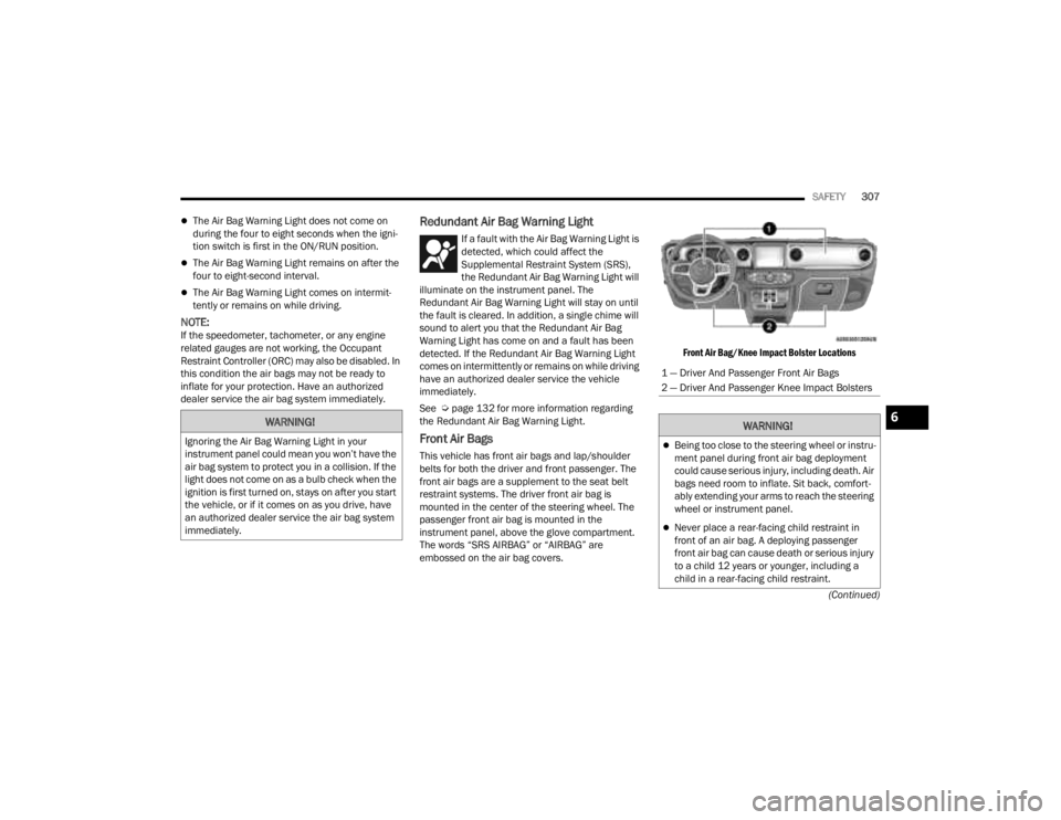
Front Air Bags
This vehicle has front air bags and lap/shoulder
belts for both the driver and front passenger. The
front air bags are a supplement to the seat belt
restraint systems. The driver front air bag is
mounted in the center of the steering wheel. The
passenger front air bag is mounted in the
instrument panel, above the glove compartment.
The words “SRS AIRBAG” or “AIRBAG” are
embossed on the air bag covers.
Front Air Bag/Knee Impact Bolster Locations
WARNING!
Ignoring the Air Bag Warning Light in your
instrument panel could mean you won’t have the
air bag system to protect you in a collision. If the
light does not come on as a bulb check when the
ignition is first turned on, stays on after you start
the vehicle, or if it comes on as you drive, have
an authorized dealer service the air bag system
immediately.
1 — Driver And Passenger Front Air Bags
2 — Driver And Passenger Knee Impact Bolsters
WARNING!
Being too close to the steering wheel or instru
-
ment panel during front air bag deployment
could cause serious injury, including death. Air
bags need room to inflate. Sit back, comfort -
ably extending your arms to reach the steering
wheel or instrument panel.
Never place a rear-facing child restraint in
front of an air bag. A deploying passenger
front air bag can cause death or serious injury
to a child 12 years or younger, including a
child in a rear-facing child restraint.
6
23_JT_OM_EN_USC_t.book Page 307
Page 332 of 448
330SAFETY
(Continued)
PERIODIC SAFETY CHECKS YOU SHOULD
M
AKE OUTSIDE THE VEHICLE
Tires
Examine tires for excessive tread wear and uneven
wear patterns. Check for stones, nails, glass, or
other objects lodged in the tread or sidewall.
Inspect the tread for cuts and cracks. Inspect
sidewalls for cuts, cracks, and bulges. Check the
lug nut/bolt torque for tightness. Check the tires
(including spare) for proper cold inflation pressure.
Lights
Have someone observe the operation of brake
lights and exterior lights while you work the
controls. Check turn signal and high beam
indicator lights on the instrument panel.
Door Latches
Check for proper closing, latching, and locking.
Fluid Leaks
Check the area under vehicle after overnight
parking for fuel, coolant, oil, or other fluid leaks.
Also, if gasoline fumes are detected or if fuel or
brake fluid leaks are suspected, the cause should
be located and corrected immediately.
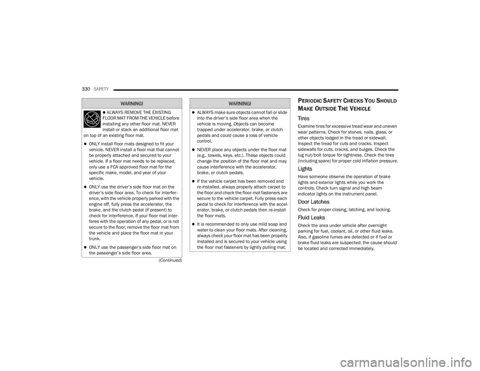
ALWAYS REMOVE THE EXISTING
FLOOR MAT FROM THE VEHICLE before
installing any other floor mat. NEVER
install or stack an additional floor mat
on top of an existing floor mat.
ONLY install floor mats designed to fit your
vehicle. NEVER install a floor mat that cannot
be properly attached and secured to your
vehicle. If a floor mat needs to be replaced,
only use a FCA approved floor mat for the
specific make, model, and year of your
vehicle.
ONLY use the driver’s side floor mat on the
driver’s side floor area. To check for interfer -
ence, with the vehicle properly parked with the
engine off, fully press the accelerator, the
brake, and the clutch pedal (if present) to
check for interference. If your floor mat inter -
feres with the operation of any pedal, or is not
secure to the floor, remove the floor mat from
the vehicle and place the floor mat in your
trunk.
ONLY use the passenger’s side floor mat on
the passenger’s side floor area.
WARNING!
ALWAYS make sure objects cannot fall or slide
into the driver’s side floor area when the
vehicle is moving. Objects can become
trapped under accelerator, brake, or clutch
pedals and could cause a loss of vehicle
control.
NEVER place any objects under the floor mat
(e.g., towels, keys, etc.). These objects could
change the position of the floor mat and may
cause interference with the accelerator,
brake, or clutch pedals.
If the vehicle carpet has been removed and
re-installed, always properly attach carpet to
the floor and check the floor mat fasteners are
secure to the vehicle carpet. Fully press each
pedal to check for interference with the accel -
erator, brake, or clutch pedals then re-install
the floor mats.
It is recommended to only use mild soap and
water to clean your floor mats. After cleaning,
always check your floor mat has been properly
installed and is secured to your vehicle using
the floor mat fasteners by lightly pulling mat.
WARNING!
23_JT_OM_EN_USC_t.book Page 330