torque JEEP GLADIATOR 2023 Owners Manual
[x] Cancel search | Manufacturer: JEEP, Model Year: 2023, Model line: GLADIATOR, Model: JEEP GLADIATOR 2023Pages: 448, PDF Size: 17.37 MB
Page 10 of 448
8
TECHNICAL SPECIFICATIONS
VEHICLE IDENTIFICATION NUMBER (VIN)......... 418
BRAKE SYSTEM .................................................. 418
WHEEL AND TIRE TORQUE SPECIFICATIONS .. 418Torque Specifications ................................... 418
FUEL REQUIREMENTS — GASOLINE ENGINE ... 419
3.6L Engine.................................................... 419
Reformulated Gasoline ................................. 419Materials Added To Fuel ............................... 419
Gasoline/Oxygenate Blends ......................... 420Do Not Use E-85 In Non-Flex Fuel
Vehicles .......................................................... 420
CNG And LP Fuel System Modifications ...... 420
Methylcyclopentadienyl Manganese
Tricarbonyl (MMT) In Gasoline...................... 420Fuel System Cautions ................................... 420
FUEL REQUIREMENTS – DIESEL ENGINE ........ 421
Diesel Fuel Specifications ............................ 421
Biodiesel Fuel Requirements ....................... 422
FLUID CAPACITIES .............................................. 423
ENGINE FLUIDS AND LUBRICANTS ................... 424 CHASSIS FLUIDS AND LUBRICANTS .................42
7
CUSTOMER ASSISTANCE
SUGGESTIONS FOR OBTAINING SERVICE FOR
YOUR VEHICLE .................................................... 428
Prepare For The Appointment ...................... 428Prepare A List ................................................ 428Be Reasonable With Requests..................... 428
IF YOU NEED ASSISTANCE ................................ 428
Roadside Assistance..................................... 428
FCA US LLC Customer Center....................... 430
FCA Canada Inc. Customer Center............... 430
Mexico ............................................................ 430
Puerto Rico And U.S. Virgin Islands.............. 430Customer Assistance For The Hearing Or
Speech Impaired (TDD/TTY) ......................... 430
Service Contract ........................................... 430 WARRANTY INFORMATION ................................ 431
MOPAR® PARTS ................................................. 431
REPORTING SAFETY DEFECTS .......................... 431
In The 50 United States And
Washington, D.C............................................ 431
In Canada ...................................................... 431
PUBLICATION ORDER FORMS .......................... 431
CHANGE OF OWNERSHIP OR ADDRESS .......... 432
GENERAL INFORMATION.................................... 432
23_JT_OM_EN_USC_t.book Page 8
Page 30 of 448
28GETTING TO KNOW YOUR VEHICLE
NOTE:Always use this device when carrying children.
After engaging the child lock on both rear doors,
check for effective engagement by trying to open a
door with the internal handle. Once the
Child-Protection Door Lock system is engaged, it is
impossible to open the doors from inside the
vehicle. Before getting out of the vehicle, be sure to
check that there is no one left inside.
FRONT DOOR REMOVAL
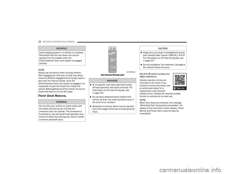
Door Removal Warning Label
Use this QR code to access your
digital experience.
Outside rearview mirrors are
mounted on the doors. If you
choose to remove the doors, see
an authorized dealer for a
replacement cowl-mounted
outside mirror. Federal law requires outside
mirrors on vehicles for on-road use.
NOTE:When front doors are removed, the message
“Blind Spot Alert Temporarily Unavailable” will
display in the instrument cluster display. Power
Mirrors and Power Door Locks will also be
unavailable.
WARNING!
Avoid trapping anyone in a vehicle in a collision.
Remember that the rear doors can only be
opened from the outside when the
Child-Protection Door Lock system is engaged
(locked).
WARNING!
Do not drive your vehicle on public roads with
the doors removed as you will lose the
protection they can provide. This procedure is
furnished for use during off-road operation only.
Failure to follow this warning can result in death
or serious personal injury.
WARNING!
All occupants must wear seat belts during
off-road operation with doors removed. For
information on off-road driving tips, see
Ú
page 207.
Do not store detached doors inside of the
vehicle, as they may cause personal injury in
the event of an accident.
Assistance to remove doors may by required
due to the weight of the door to avoid personal
injury.
CAUTION!
Hinge pins can break if overtightened during
door reinstall (Max Torque: 5.88 ft·lb / 8 N·m).
For information on off-road driving tips, see
Úpage 207.
Do not overtighten Torx fasteners. Damage to
the vehicle’s parts will occur.
23_JT_OM_EN_USC_t.book Page 28
Page 33 of 448
GETTING TO KNOW YOUR VEHICLE31
Replacing The Wiring Connector Into The Wiring
Harness
To reinstall the wiring connector on the vehicle’s
door into the harness just inside the vehicle,
proceed as follows:
NOTE:Make sure there is plenty of slack on the wiring
connector during installation. Close the door
slightly to provide more slack if needed.
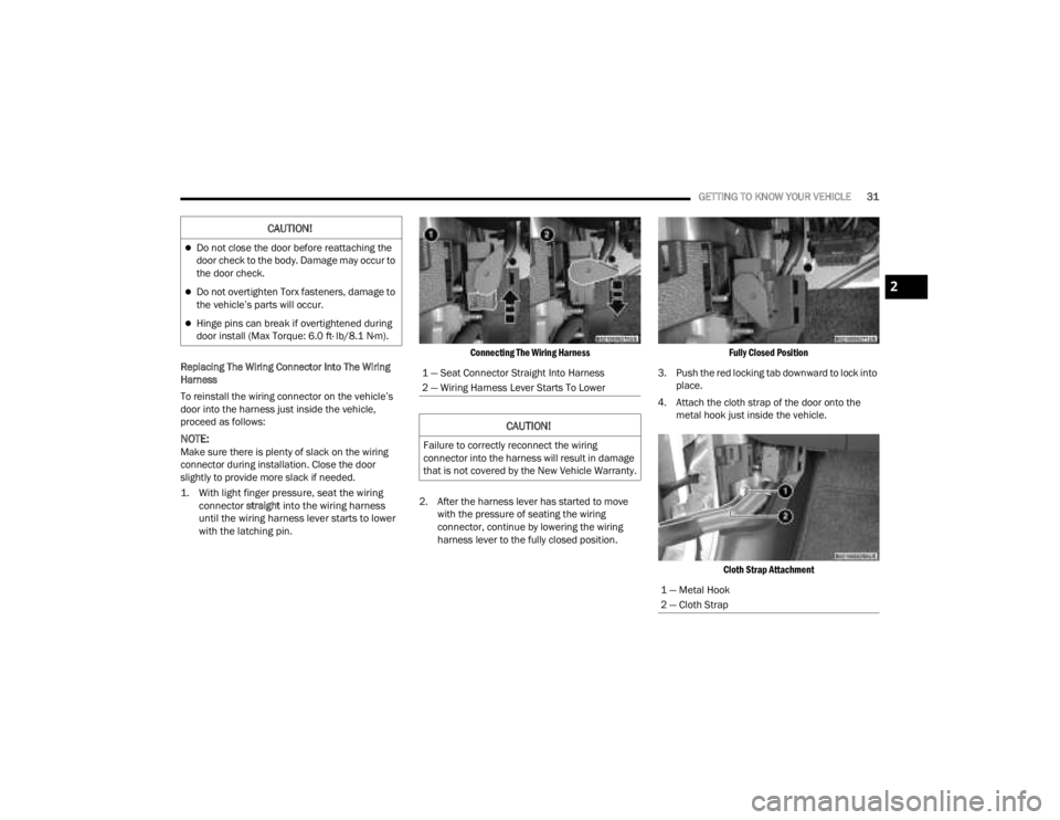
1. With light finger pressure, seat the wiring connector
straight
into the wiring harness
until the wiring harness lever starts to lower
with the latching pin.
Connecting The Wiring Harness
2. After the harness lever has started to move with the pressure of seating the wiring
connector, continue by lowering the wiring
harness lever to the fully closed position.
Fully Closed Position
3. Push the red locking tab downward to lock into place.
4. Attach the cloth strap of the door onto the metal hook just inside the vehicle.
Cloth Strap Attachment
CAUTION!
Do not close the door before reattaching the
door check to the body. Damage may occur to
the door check.
Do not overtighten Torx fasteners, damage to
the vehicle’s parts will occur.
Hinge pins can break if overtightened during
door install (Max Torque: 6.0 ft· lb/8.1 N·m).
1 — Seat Connector Straight Into Harness
2 — Wiring Harness Lever Starts To Lower
CAUTION!
Failure to correctly reconnect the wiring
connector into the harness will result in damage
that is not covered by the New Vehicle Warranty.
1 — Metal Hook
2 — Cloth Strap
2
23_JT_OM_EN_USC_t.book Page 31
Page 34 of 448
32GETTING TO KNOW YOUR VEHICLE
5. Replace wiring access doors.
NOTE:
When reinstalling the door check arm attachment
screw, screw torque should be between 11.76 ft·lb /
16 N·m and 27.9 ft·lb / 38 N·m.
REAR DOOR REMOVAL
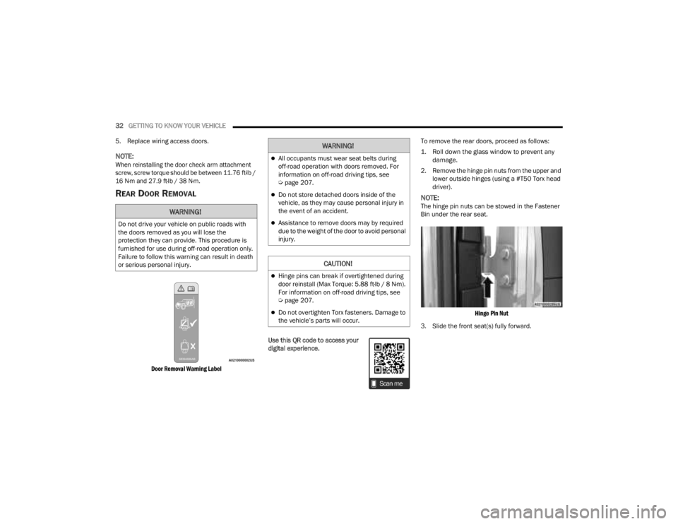
Door Removal Warning Label
Use this QR code to access your
digital experience. To remove the rear doors, proceed as follows:
1. Roll down the glass window to prevent any
damage.
2. Remove the hinge pin nuts from the upper and lower outside hinges (using a #T50 Torx head
driver).
NOTE:The hinge pin nuts can be stowed in the Fastener
Bin under the rear seat.
Hinge Pin Nut
3. Slide the front seat(s) fully forward.WARNING!
Do not drive your vehicle on public roads with
the doors removed as you will lose the
protection they can provide. This procedure is
furnished for use during off-road operation only.
Failure to follow this warning can result in death
or serious personal injury.
WARNING!
All occupants must wear seat belts during
off-road operation with doors removed. For
information on off-road driving tips, see
Ú page 207.
Do not store detached doors inside of the
vehicle, as they may cause personal injury in
the event of an accident.
Assistance to remove doors may by required
due to the weight of the door to avoid personal
injury.
CAUTION!
Hinge pins can break if overtightened during
door reinstall (Max Torque: 5.88 ft·lb / 8 N·m).
For information on off-road driving tips, see
Úpage 207.
Do not overtighten Torx fasteners. Damage to
the vehicle’s parts will occur.
23_JT_OM_EN_USC_t.book Page 32
Page 35 of 448
GETTING TO KNOW YOUR VEHICLE33
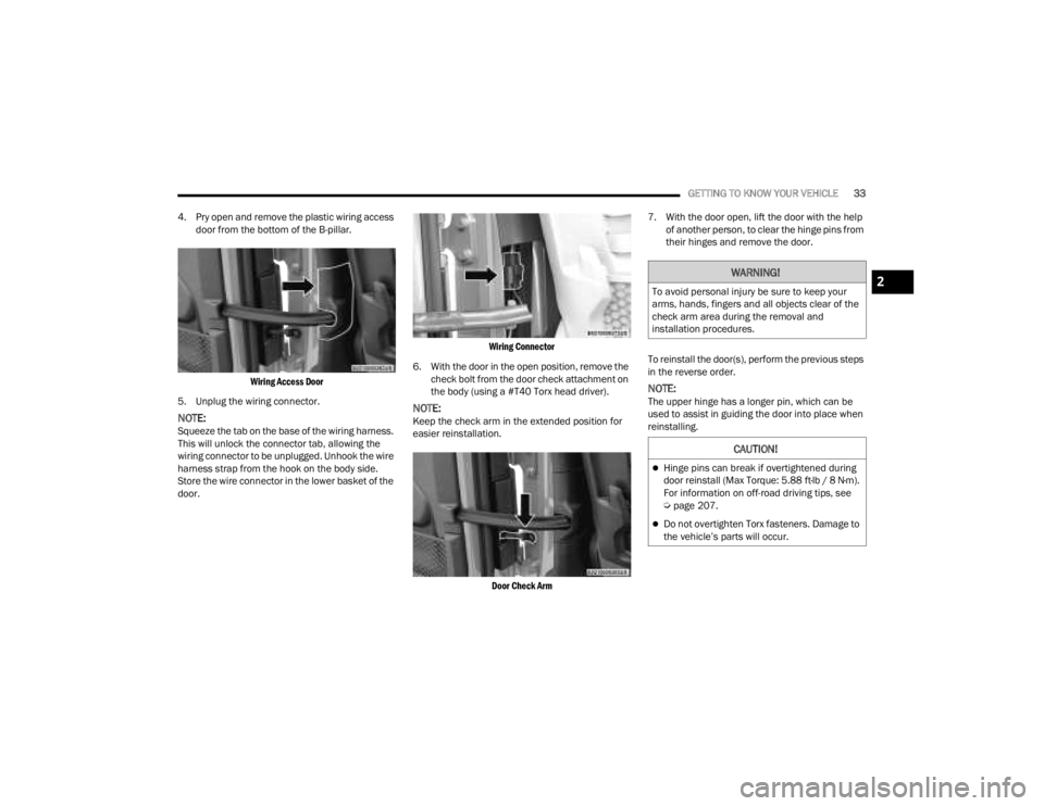
4. Pry open and remove the plastic wiring access door from the bottom of the B-pillar.
Wiring Access Door
5. Unplug the wiring connector.
NOTE:Squeeze the tab on the base of the wiring harness.
This will unlock the connector tab, allowing the
wiring connector to be unplugged. Unhook the wire
harness strap from the hook on the body side.
Store the wire connector in the lower basket of the
door.
Wiring Connector
6. With the door in the open position, remove the check bolt from the door check attachment on
the body (using a #T40 Torx head driver).
NOTE:Keep the check arm in the extended position for
easier reinstallation.
Door Check Arm
7. With the door open, lift the door with the help
of another person, to clear the hinge pins from
their hinges and remove the door.
To reinstall the door(s), perform the previous steps
in the reverse order.
NOTE:The upper hinge has a longer pin, which can be
used to assist in guiding the door into place when
reinstalling.
WARNING!
To avoid personal injury be sure to keep your
arms, hands, fingers and all objects clear of the
check arm area during the removal and
installation procedures.
CAUTION!
Hinge pins can break if overtightened during
door reinstall (Max Torque: 5.88 ft·lb / 8 N·m).
For information on off-road driving tips, see
Ú page 207.
Do not overtighten Torx fasteners. Damage to
the vehicle’s parts will occur.
2
23_JT_OM_EN_USC_t.book Page 33
Page 37 of 448
GETTING TO KNOW YOUR VEHICLE35
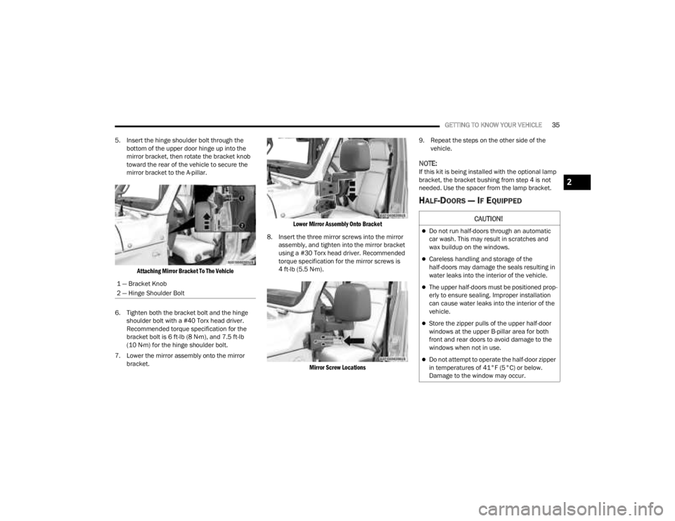
5. Insert the hinge shoulder bolt through the bottom of the upper door hinge up into the
mirror bracket, then rotate the bracket knob
toward the rear of the vehicle to secure the
mirror bracket to the A-pillar.
Attaching Mirror Bracket To The Vehicle
6. Tighten both the bracket bolt and the hinge shoulder bolt with a #40 Torx head driver.
Recommended torque specification for the
bracket bolt is 6 ft-lb (8 N·m), and 7.5 ft-lb
(10 N·m) for the hinge shoulder bolt.
7. Lower the mirror assembly onto the mirror bracket.
Lower Mirror Assembly Onto Bracket
8. Insert the three mirror screws into the mirror assembly, and tighten into the mirror bracket
using a #30 Torx head driver. Recommended
torque specification for the mirror screws is
4 ft-lb (5.5 N·m).
Mirror Screw Locations
9. Repeat the steps on the other side of the
vehicle.
NOTE:If this kit is being installed with the optional lamp
bracket, the bracket bushing from step 4 is not
needed. Use the spacer from the lamp bracket.
HALF-DOORS — IF EQUIPPED
1 — Bracket Knob
2 — Hinge Shoulder Bolt
CAUTION!
Do not run half-doors through an automatic
car wash. This may result in scratches and
wax buildup on the windows.
Careless handling and storage of the
half-doors may damage the seals resulting in
water leaks into the interior of the vehicle.
The upper half-doors must be positioned prop -
erly to ensure sealing. Improper installation
can cause water leaks into the interior of the
vehicle.
Store the zipper pulls of the upper half-door
windows at the upper B-pillar area for both
front and rear doors to avoid damage to the
windows when not in use.
Do not attempt to operate the half-door zipper
in temperatures of 41°F (5°C) or below.
Damage to the window may occur.
2
23_JT_OM_EN_USC_t.book Page 35
Page 38 of 448
36GETTING TO KNOW YOUR VEHICLE
Use this QR code to access your
digital experience.
This vehicle may be equipped with
half-doors. To install the
half-doors in the vehicle, follow
the instruction sheet packaged in
the box the doors were received
in. Replacement parts may be purchased through
Mopar® Service.
Half-Door Installation
To install the front or rear half-doors, proceed as
follows:
1. Remove the full doors from the vehicle. For front door removal, see
Ú
page 28
. For rear
door removal, see Ú
page 32.
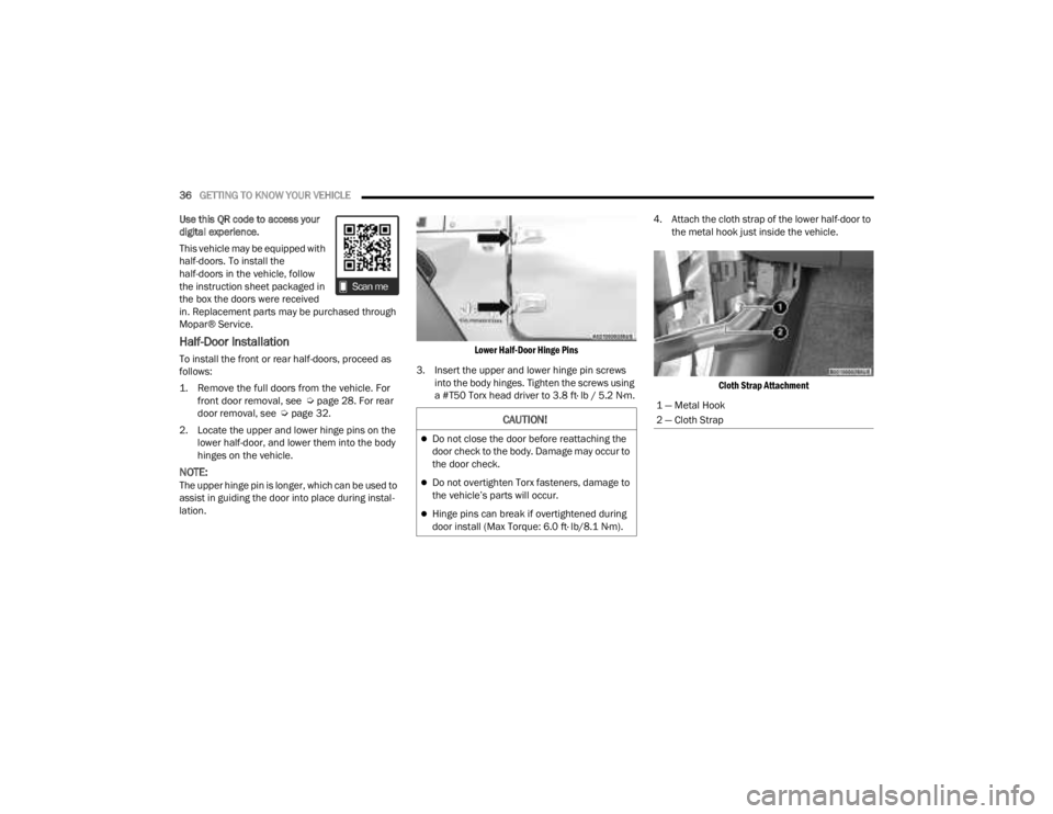
2. Locate the upper and lower hinge pins on the lower half-door, and lower them into the body
hinges on the vehicle.
NOTE:The upper hinge pin is longer, which can be used to
assist in guiding the door into place during instal -
lation.
Lower Half-Door Hinge Pins
3. Insert the upper and lower hinge pin screws into the body hinges. Tighten the screws using
a #T50 Torx head driver to 3.8 ft· lb / 5.2 N·m. 4. Attach the cloth strap of the lower half-door to
the metal hook just inside the vehicle.
Cloth Strap Attachment
CAUTION!
Do not close the door before reattaching the
door check to the body. Damage may occur to
the door check.
Do not overtighten Torx fasteners, damage to
the vehicle’s parts will occur.
Hinge pins can break if overtightened during
door install (Max Torque: 6.0 ft· lb/8.1 N·m).
1 — Metal Hook
2 — Cloth Strap
23_JT_OM_EN_USC_t.book Page 36
Page 40 of 448
38GETTING TO KNOW YOUR VEHICLE
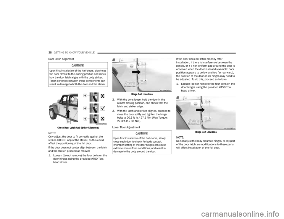
Door Latch Alignment
Check Door Latch And Striker Alignment
NOTE:Only adjust the door to fit correctly against the
striker. DO NOT adjust the striker, as this could
affect the positioning of the full door.
If the door does not center align between the latch
and the striker, proceed as follows:
1. Loosen (do not remove) the four bolts on the door hinges using the provided #T50 Torx
head driver.
Hinge Bolt Locations
2. With the bolts loose, hold the door in the almost closing position, and check that the
latch and striker align.
3. With the latch and striker aligned, proceed to close the door softly and tighten the hinge
bolts to 20.3 ft· lb / 27.5 N·m (Max Torque:
27.3 ft· lb / 37 N·m).
Lower Door Adjustment If the door does not latch properly after
installation, if there is interference between the
panels, or if a non-uniform gap around the door is
observed when the door is closed (example: door
position appears to be low and too far rearward),
the position of the door on its hinges may need to
be adjusted. To do this, proceed as follows:
1. Loosen (do not remove) the four bolts on the
door hinges using the provided #T50 Torx
head driver.
Hinge Bolt Locations
NOTE:Do not adjust the body mounted hinges, or any part
of the door latch, as modifications to these parts
will affect installation of the full door.
CAUTION!
Upon first installation of the half-doors, slowly set
the door almost to the closing position and check
how the door latch aligns with the body striker.
Touch condition between these components can
result in damage to both the door and the striker.
CAUTION!
Upon first installation of the half-doors, slowly
close each door to check for body contact.
Improper setting of the door hinges can cause
extreme non-uniform conditions, and result in
damage to the body around the door.
23_JT_OM_EN_USC_t.book Page 38
Page 41 of 448
GETTING TO KNOW YOUR VEHICLE39
2. With the bolts loose, the door can be moved forward by pushing the door handle toward the
front of the vehicle, and/or upward by grabbing
the door handle and lifting towards the roof.
3. Once the gaps between the door and vehicle body are uniform around the entire door,
tighten the door hinge bolts to 20.3 ft· lb /
27.5 N·m (Max Torque: 27.3 ft· lb / 37 N·m).
Upper Door Adjustment
After installation of the half-doors, if water leaks or
wind noise is observed, the seal of the upper
half-door to the door opening may need to be
adjusted.
To determine if the upper half-door needs to be
adjusted, proceed as follows:
1. Determine which door is affected.
2. Open the affected door and hold a dollar-size piece of paper along the top of the door
opening against the vehicle near where the
leak/noise was observed. Make sure half of
the paper is above the area where the door
seal contacts the door opening, while the other
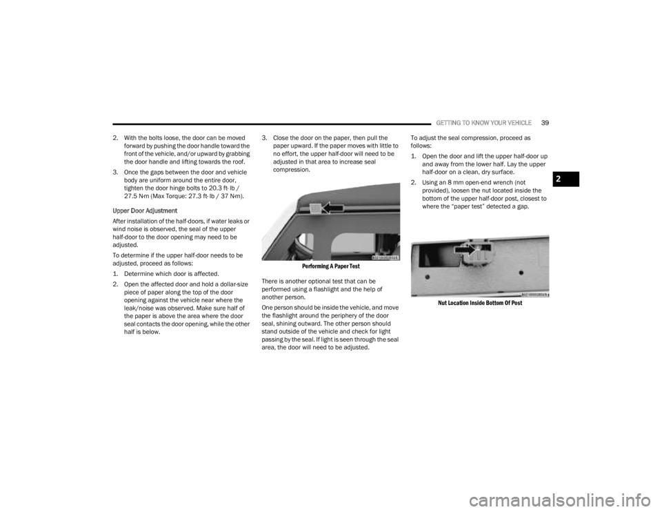
half is below. 3. Close the door on the paper, then pull the
paper upward. If the paper moves with little to
no effort, the upper half-door will need to be
adjusted in that area to increase seal
compression.
Performing A Paper Test
There is another optional test that can be
performed using a flashlight and the help of
another person.
One person should be inside the vehicle, and move
the flashlight around the periphery of the door
seal, shining outward. The other person should
stand outside of the vehicle and check for light
passing by the seal. If light is seen through the seal
area, the door will need to be adjusted. To adjust the seal compression, proceed as
follows:
1. Open the door and lift the upper half-door up
and away from the lower half. Lay the upper
half-door on a clean, dry surface.
2. Using an 8 mm open-end wrench (not provided), loosen the nut located inside the
bottom of the upper half-door post, closest to
where the “paper test” detected a gap.
Nut Location Inside Bottom Of Post
2
23_JT_OM_EN_USC_t.book Page 39
Page 43 of 448
GETTING TO KNOW YOUR VEHICLE41
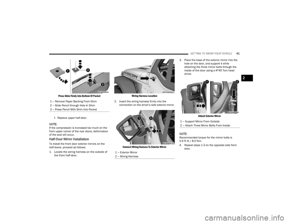
Press Shim Firmly Into Bottom Of Pocket
f. Replace upper half-door.
NOTE:If the compression is increased too much on the
front upper corner of the rear doors, deformation
of the seal will occur.
Half-Door Mirror Installation
To install the front door exterior mirrors on the
half-doors, proceed as follows:
1. Locate the wiring harness on the outside of the front half-door.
Wiring Harness Location
2. Insert the wiring harness firmly into the connection on the driver’s side exterior mirror.
Connect Wiring Harness To Exterior Mirror
3. Place the base of the exterior mirror into the
hole on the door, and support it while
attaching the three mirror bolts through the
inside of the door using a #T40 Torx head
driver.
Attach Exterior Mirror
NOTE:Recommended torque for the mirror bolts is
5.9 ft· lb / 8.0 N·m.
4. Repeat steps 1-3 on the opposite side front door.
1 — Remove Paper Backing From Shim
2 — Slide Pencil through Hole In Shim
3 — Press Pencil With Shim Into Pocket
1 — Exterior Mirror
2 — Wiring Harness
1 — Support Mirror From Outside
2 — Attach Three Mirror Bolts From Inside
2
23_JT_OM_EN_USC_t.book Page 41