regulator - installation JEEP GRAND CHEROKEE 2002 WJ / 2.G Workshop Manual
[x] Cancel search | Manufacturer: JEEP, Model Year: 2002, Model line: GRAND CHEROKEE, Model: JEEP GRAND CHEROKEE 2002 WJ / 2.GPages: 2199, PDF Size: 76.01 MB
Page 355 of 2199
CHARGING
TABLE OF CONTENTS
page page
CHARGING
DESCRIPTION.........................24
OPERATION...........................24
DIAGNOSIS AND TESTING - CHARGING
SYSTEM............................24
SPECIFICATIONS
GENERATOR RATINGS - GAS POWERED . . 25
TORQUE - GAS POWERED.............25
SPECIAL TOOLS.......................26
BATTERY TEMPERATURE SENSOR
DESCRIPTION.........................26OPERATION...........................26
REMOVAL.............................26
INSTALLATION.........................26
GENERATOR
DESCRIPTION.........................27
OPERATION...........................27
REMOVAL.............................27
INSTALLATION.........................28
VOLTAGE REGULATOR
DESCRIPTION.........................28
OPERATION...........................28
CHARGING
DESCRIPTION
The charging system consists of:
²Generator
²Electronic Voltage Regulator (EVR) circuitry
within the Powertrain Control Module (PCM)
²Ignition switch
²Battery (refer to 8, Battery for information)
²Battery temperature sensor
²Generator Lamp (if equipped)
²Check Gauges Lamp (if equipped)
²Voltmeter (refer to 8, Instrument Cluster for
information)
²Wiring harness and connections (refer to 8, Wir-
ing for information)
OPERATION
The charging system is turned on and off with the
ignition switch. The system is on when the engine is
running and the ASD relay is energized. When the
ASD relay is on, voltage is supplied to the ASD relay
sense circuit at the PCM. This voltage is connected
through the PCM and supplied to one of the genera-
tor field terminals (Gen. Source +) at the back of the
generator.
The amount of DC current produced by the gener-
ator is controlled by the EVR (field control) circuitry
contained within the PCM. This circuitry is con-
nected in series with the second rotor field terminal
and ground.
A battery temperature sensor, located in the bat-
tery tray housing, is used to sense battery tempera-
ture. This temperature data, along with data from
monitored line voltage, is used by the PCM to vary
the battery charging rate. This is done by cycling theground path to control the strength of the rotor mag-
netic field. The PCM then compensates and regulates
generator current output accordingly.
All vehicles are equipped with On-Board Diagnos-
tics (OBD). All OBD-sensed systems, including EVR
(field control) circuitry, are monitored by the PCM.
Each monitored circuit is assigned a Diagnostic Trou-
ble Code (DTC). The PCM will store a DTC in elec-
tronic memory for certain failures it detects. Refer to
Diagnostic Trouble Codes in; Powertrain Control
Module; Electronic Control Modules for more DTC
information.
The Check Gauges Lamp (if equipped) monitors:
charging system voltage,engine coolant tempera-
ture and engine oil pressure. If an extreme condition
is indicated, the lamp will be illuminated. This is
done as reminder to check the three gauges. The sig-
nal to activate the lamp is sent via the CCD bus cir-
cuits. The lamp is located on the instrument panel.
Refer to 8, Instrument Cluster for additional infor-
mation.
DIAGNOSIS AND TESTING - CHARGING
SYSTEM
The following procedures may be used to diagnose
the charging system if:
²the check gauges lamp (if equipped) is illumi-
nated with the engine running
²the voltmeter (if equipped) does not register
properly
²an undercharged or overcharged battery condi-
tion occurs.
Remember that an undercharged battery is often
caused by:
²accessories being left on with the engine not
running
8F - 24 CHARGINGWJ
Page 359 of 2199
INSTALLATION
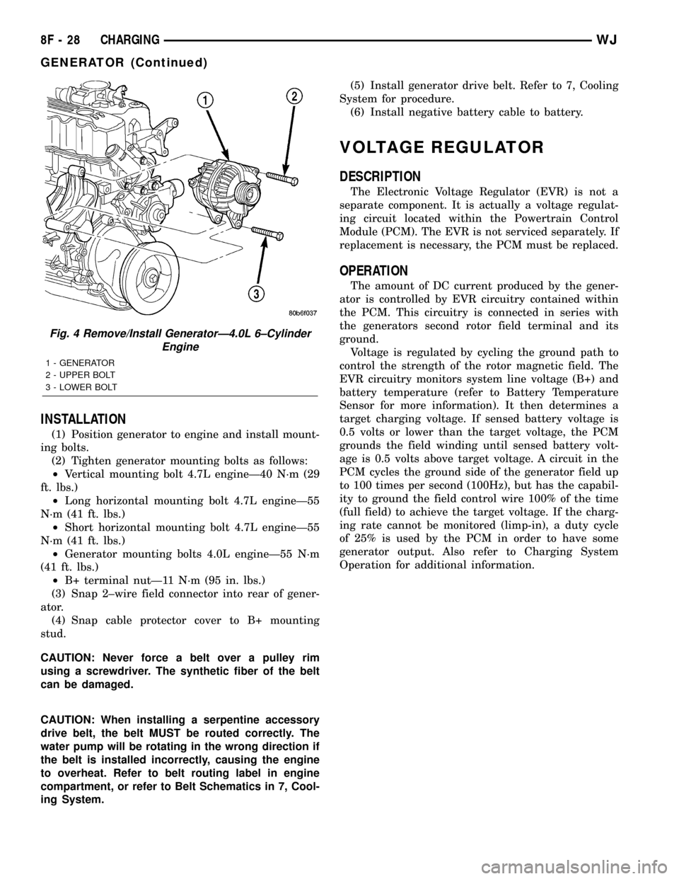
(1) Position generator to engine and install mount-
ing bolts.
(2) Tighten generator mounting bolts as follows:
²Vertical mounting bolt 4.7L engineÐ40 N´m (29
ft. lbs.)
²Long horizontal mounting bolt 4.7L engineÐ55
N´m (41 ft. lbs.)
²Short horizontal mounting bolt 4.7L engineÐ55
N´m (41 ft. lbs.)
²Generator mounting bolts 4.0L engineÐ55 N´m
(41 ft. lbs.)
²B+ terminal nutÐ11 N´m (95 in. lbs.)
(3) Snap 2±wire field connector into rear of gener-
ator.
(4) Snap cable protector cover to B+ mounting
stud.
CAUTION: Never force a belt over a pulley rim
using a screwdriver. The synthetic fiber of the belt
can be damaged.
CAUTION: When installing a serpentine accessory
drive belt, the belt MUST be routed correctly. The
water pump will be rotating in the wrong direction if
the belt is installed incorrectly, causing the engine
to overheat. Refer to belt routing label in engine
compartment, or refer to Belt Schematics in 7, Cool-
ing System.(5) Install generator drive belt. Refer to 7, Cooling
System for procedure.
(6) Install negative battery cable to battery.
VOLTAGE REGULATOR
DESCRIPTION
The Electronic Voltage Regulator (EVR) is not a
separate component. It is actually a voltage regulat-
ing circuit located within the Powertrain Control
Module (PCM). The EVR is not serviced separately. If
replacement is necessary, the PCM must be replaced.
OPERATION
The amount of DC current produced by the gener-
ator is controlled by EVR circuitry contained within
the PCM. This circuitry is connected in series with
the generators second rotor field terminal and its
ground.
Voltage is regulated by cycling the ground path to
control the strength of the rotor magnetic field. The
EVR circuitry monitors system line voltage (B+) and
battery temperature (refer to Battery Temperature
Sensor for more information). It then determines a
target charging voltage. If sensed battery voltage is
0.5 volts or lower than the target voltage, the PCM
grounds the field winding until sensed battery volt-
age is 0.5 volts above target voltage. A circuit in the
PCM cycles the ground side of the generator field up
to 100 times per second (100Hz), but has the capabil-
ity to ground the field control wire 100% of the time
(full field) to achieve the target voltage. If the charg-
ing rate cannot be monitored (limp-in), a duty cycle
of 25% is used by the PCM in order to have some
generator output. Also refer to Charging System
Operation for additional information.
Fig. 4 Remove/Install GeneratorÐ4.0L 6±Cylinder
Engine
1 - GENERATOR
2 - UPPER BOLT
3 - LOWER BOLT
8F - 28 CHARGINGWJ
GENERATOR (Continued)
Page 530 of 2199
POWER WINDOWS
TABLE OF CONTENTS
page page
POWER WINDOWS
DESCRIPTION.........................33
OPERATION...........................34
DIAGNOSIS AND TESTING - POWER
WINDOWS...........................34
POWER WINDOW SWITCH
DESCRIPTION.........................36
OPERATION...........................36
DIAGNOSIS AND TESTING - POWER
WINDOW SWITCH.....................37REMOVAL.............................37
INSTALLATION.........................38
WINDOW MOTOR
DESCRIPTION.........................38
OPERATION...........................38
DIAGNOSIS AND TESTING - WINDOW
MOTOR .............................38
REMOVAL.............................39
INSTALLATION.........................39
POWER WINDOWS
DESCRIPTION
Power operated driver side and passenger side
front and rear door windows are standard factory-in-
stalled equipment on this model. The power window
system allows each of the door windows to be raised
or lowered electrically by operating a switch on the
trim panel for that door. Additionally, the master
switches on the driver side front door trim panel
allow all of the windows to be operated from the
driver seat position. A power window lockout switch
on the driver side front door trim panel will allow the
driver to disable all of the passenger door window
switches.
The power window system functionally operates
when the ignition switch is in the On position. How-
ever, a unique feature of this system will allow the
power windows to be operated for up to forty-five sec-
onds after the ignition switch is turned to the Off
position, or until a front door is opened, whichever
occurs first.
An auto-down feature allows the driver side front
door window to be lowered all the way, even if the
window switch is released. The driver side front door
window switch must be depressed in the down direc-
tion to a second detent to begin an auto-down event.
Depressing the switch again in any direction cancel
the auto-down event and begin movement in the
direction specified.
This group covers the following components of the
power window system:
²Power window switches
²Power window motors.
Certain functions and features of the power win-
dow system rely upon resources shared with other
electronic modules in the vehicle over the Program-mable Communications Interface (PCI) data bus net-
work. The PCI data bus network allows the sharing
of sensor information. This helps to reduce wire har-
ness complexity, internal controller hardware, and
component sensor current loads. At the same time,
this system provides increased reliability, enhanced
diagnostics, and allows the addition of many new fea-
ture capabilities. For diagnosis of these electronic
modules or of the PCI data bus network, the use of a
DRB scan tool and the proper Diagnostic Procedures
manual are recommended.
The other electronic modules that may affect power
window system operation are as follows:
²Body Control Module (BCM)- (Refer to 8 -
ELECTRICAL/ELECTRONIC CONTROL MOD-
ULES/BODY CONTROL/CENTRAL TIMER MODUL
- DESCRIPTION) for more information.
²Driver Door Module (DDM)-(Refer to 8 -
ELECTRICAL/ELECTRONIC CONTROL MOD-
ULES/DRIVER DOOR MODULE - DESCRIPTION)
for more information.
²Passenger Door Module (PDM)- (Refer to 8 -
ELECTRICAL/ELECTRONIC CONTROL MOD-
ULES/DRIVER DOOR MODULE - DESCRIPTION)
for more information.
This group covers diagnosis and service of only the
electrical components in the power window system.
For service of mechanical components, such as the
regulator, lift plate, window tracks, or glass refer to
Body. Refer to the appropriate wiring information.
The wiring information includes wiring diagrams,
proper wire and connector repair procedures, details
of wire harness routing and retention, connector pin-
out information and location views for the various
wire harness connectors, splices and grounds. Follow-
ing are general descriptions of the major components
in the power window system.
WJPOWER WINDOWS 8N - 33
Page 532 of 2199
PASSENGER SIDE FRONT AND REAR WINDOWS
INOPERATIVE
If the driver side front and rear power windows
operate, but the passenger side front and rear do not,
use a DRB scan tool and the proper Diagnostic Pro-
cedures manual to check the PCI data bus for proper
operation.
ONE WINDOW INOPERATIVE
The window glass and regulator mechanism must
be free to slide up and down for the power window
motor to function properly. If the window glass and
regulator is not free to move up and down, the motor
will overload and trip the integral circuit breaker. To
determine if the window glass and regulator are free,
disconnect the regulator plate from the glass. Then
slide the window up and down by hand.
There is an alternate method to check if the win-
dow glass and regulator mechanism is free. Position
the glass between the up and down stops. Then,
shake the glass in the door. Check that the glass can
be moved slightly from side to side, front to rear, and
up and down. Then check that the glass is not bound
tight in the tracks.
If the window glass and regulator mechanism is
free, refer toDoor Modulein Electrical, Power Win-
dows. If the glass is not free, inspect the window
glass mounting and operating hardware for damage
or improperly installed components. Refer toBodyto
check for proper installation or damage of the win-
dow glass mounting and operating hardware.
DOOR MODULE
NOTE: The following tests may not prove conclu-
sive in the diagnosis of this component. The most
reliable, efficient, and accurate means to diagnose
this component requires the use of a DRB scan tool
and the proper Diagnostic Procedures manual.
If the problem being diagnosed is a rear door win-
dow that does not operate from the rear door switch,
but does operate from the master switch on the
driver side front door, (Refer to 8 - ELECTRICAL/
POWER WINDOWS/POWER WINDOW SWITCH -
DIAGNOSIS AND TESTING). If the problem is a
passenger side front or rear window that operates
from the switch on that door, but does not operate
from the master switch on the driver side front door,
use a DRB scan tool and the proper Diagnostic Pro-
cedures manual to diagnose the circuitry of both door
modules and the PCI data bus. For complete circuit
diagrams, refer to the appropriate wiring informa-
tion. The wiring information includes wiring dia-
grams, proper wire and connector repair procedures,
details of wire harness routing and retention, connec-tor pin-out information and location views for the
various wire harness connectors, splices and grounds.
(1) Disconnect and isolate the battery negative
cable. Remove the trim panel from the front door, but
do not disconnect the door wire harness connectors
from the door module. Go to Step 2.
(2) Check the 15-way door wire harness connector
for the door module to see that it is fully seated in
the door module connector receptacle. If OK, go to
Step 3. If not OK, properly connect the 15-way door
wire harness connector for the door module to the
door module connector receptacle.
(3) Disconnect the 15-way door wire harness con-
nector from the door module connector receptacle.
Check for continuity between the ground circuit cav-
ity of the 15-way door wire harness connector for the
door module and a good ground. There should be con-
tinuity. If OK, go to Step 4. If not OK, repair the
open ground circuit to ground as required.
(4) Connect the battery negative cable. Check for
battery voltage at the fused B(+) circuit cavity of the
15-way door wire harness connector for the door
module. If OK, go to Step 5. If not OK, repair the
open fused B(+) circuit to the fuse in the Power Dis-
tribution Center (PDC) as required.
(5) If the inoperative window is on a front door, go
to Step 6. If the inoperative window is on a rear door
go to Step 9.
(6) Disconnect and isolate the battery negative
cable. Disconnect the door wire harness connector
from the inoperative power window motor wire har-
ness connector. Check for continuity between the
front window driver up circuit cavity of the 15-way
door wire harness connector for the door module and
a good ground. Repeat the check for the front window
driver down circuit. In each case there should be no
continuity. If OK, go to Step 7. If not OK, repair the
shorted front window driver up or down circuit as
required.
(7) Check for continuity between the front window
driver up circuit cavities of the 15-way door wire har-
ness connector for the door module and the door wire
harness connector for the power window motor.
Repeat the check for the front window driver down
circuit. In each case there should be continuity. If
OK, go to Step 8. If not OK, repair the open front
window driver up or down circuit as required.
(8) Reconnect the 15-way door wire harness con-
nector back into the door module connector recepta-
cle. Connect the battery negative cable. Connect the
probes of a reversible DC digital voltmeter to the
door wire harness connector for the power window
motor. Observe the voltmeter while actuating the
switch for that window in the up and down direc-
tions. There should be battery voltage for as long as
the switch is held in both the up and down positions,
WJPOWER WINDOWS 8N - 35
POWER WINDOWS (Continued)
Page 535 of 2199
INSTALLATION
(1) Position the power window switch to the rear
door trim panel switch receptacle.
(2) Press firmly and evenly on the back of the
power window switch until it snaps into rear door
trim panel switch receptacle.
(3) Install the trim panel onto the rear door. (Refer
to 23 - BODY/DOORS - REAR/TRIM PANEL -
INSTALLATION) for the procedures.
(4) Reconnect the battery negative cable.
WINDOW MOTOR
DESCRIPTION
Power operated front and rear door windows are
standard equipment on this model. Each door has a
permanent magnet reversible electric motor with an
integral right angle gearbox mechanism that oper-
ates the window regulator. In addition, each power
window motor is equipped with an integral self-reset-
ting circuit breaker to protect the motor from over-
loads.
The power window motor gearbox housing is
secured to the window regulator drum housing with
screws. The window regulators used in all four doors
are single vertical post cable-and-drum type. A
molded plastic slider guided by the post is driven by
the regulator cables. The slider raises and lowers the
window glass through a steel lift plate attachment.
Front and rear glass channels within each door guide
and stabilize each end of the glass.
The power window motor and gearbox assembly
cannot be repaired and, if faulty or damaged, the
entire power window motor and gearbox unit must be
replaced. The window regulators are available for
service. (Refer to 23 - BODY/DOOR - FRONT/WIN-
DOW REGULATOR - REMOVAL) or (Refer to 23 -
BODY/DOORS - REAR/WINDOW REGULATOR -
REMOVAL) for the regulator service procedures.
OPERATION
A positive and negative battery connection to the
two motor terminals will cause the power window
motor to rotate in one direction. Reversing the cur-
rent through these same two connections will cause
the motor to rotate in the opposite direction.
When the power window motor operates, it rotates
the regulator cable drum through its gearbox. The
window regulator cable drum is connected through
two cables to the plastic slider on the vertical post.
As the cable drum rotates, it lets cable out on one
side of the drum, and takes cable in on the other side
of the drum. The changes in cable length move the
slider up or down the vertical post, raising or lower-
ing the window glass.If the window regulator or window glass bind,
encounter obstructions, or reach their travel limits it
overloads the power window motor. The overloading
condition causes the power window motor self-reset-
ting circuit breaker to open, which stops the motor
from running.
DIAGNOSIS AND TESTING - WINDOW MOTOR
Before you proceed with this diagnosis, confirm
proper switch operation. (Refer to 8 - ELECTRICAL/
ELECTRONIC CONTROL MODULES/DRIVER
DOOR MODULE - OPERATION) or (Refer to 8 -
ELECTRICAL/POWER WINDOWS/POWER WIN-
DOW SWITCH - OPERATION). For complete circuit
diagrams, refer to the appropriate wiring informa-
tion. The wiring information includes wiring dia-
grams, proper wire and connector repair procedures,
details of wire harness routing and retention, connec-
tor pin-out information and location views for the
various wire harness connectors, splices and grounds.
(1) Remove the trim panel from the door with the
inoperative power window. (Refer to 23 - BODY/
DOOR - FRONT/TRIM PANEL - REMOVAL) or
(Refer to 23 - BODY/DOORS - REAR/TRIM PANEL -
REMOVAL) for the procedures.
(2) Disconnect the door wire harness connector
from the power window motor wire harness connec-
tor. Apply battery current to one cavity of the power
window motor wire harness connector, and apply
ground to the other cavity of the connector. The
power window motor should operate in one direction.
Remember, if the window is in the full up or full
down position, the motor will not operate in that
direction by design. If OK, go to Step 3. If not OK,
replace the faulty power window motor.
(3) Reverse the battery and ground connections to
the two cavities of the power window motor wire har-
ness connector. The power window motor should now
operate in the other direction. Remember, if the win-
dow is in the full up or full down position, the motor
will not operate in that direction by design. If OK, go
to Step 4. If not OK, replace the faulty power window
motor.
(4) If the power window motor operates in both
directions, check the operation of the window glass
and regulator mechanism through its complete up
and down travel. There should be no binding or stick-
ing of the window glass or regulator mechanism
through the entire travel range. If not OK, (Refer to
23 - BODY/DOOR - FRONT/WINDOW REGULATOR
- REMOVAL) or (Refer to 23 - BODY/DOORS -
REAR/WINDOW REGULATOR - REMOVAL) to
check for proper installation or damage of the win-
dow glass mounting and operating hardware.
8N - 38 POWER WINDOWSWJ
POWER WINDOW SWITCH (Continued)
Page 536 of 2199
REMOVAL
(1) Disconnect and isolate the battery negative
cable.
(2) Remove the window regulator from the door.
(Refer to 23 - BODY/DOOR - FRONT/WINDOW
REGULATOR - REMOVAL) or (Refer to 23 - BODY/
DOORS - REAR/WINDOW REGULATOR -
REMOVAL) for the procedures.
(3) Place the window regulator on a suitable work
surface and remove the screws that secure the power
window motor to the window regulator.
(4) Remove the power window motor from the win-
dow regulator.
INSTALLATION
(1) Position the power window motor onto the win-
dow regulator.
(2) Install and tighten the screws that secure the
power window motor to the window regulator.
Tighten the screws to 9 N´m (80 in. lbs.).
(3) Install the window regulator onto the door.
(Refer to 23 - BODY/DOOR - FRONT/WINDOW
REGULATOR - INSTALLATION) or(Refer to 23 -
BODY/DOORS - REAR/WINDOW REGULATOR -
INSTALLATION) for the procedures.
(4) Reconnect the battery negative cable.
WJPOWER WINDOWS 8N - 39
WINDOW MOTOR (Continued)
Page 1420 of 2199
FUEL SYSTEM
TABLE OF CONTENTS
page page
FUEL DELIVERY..........................1FUEL INJECTION........................31
FUEL DELIVERY
TABLE OF CONTENTS
page page
FUEL DELIVERY
DESCRIPTION..........................2
OPERATION............................2
DIAGNOSIS AND TESTING
FUEL PRESSURE LEAK DOWN TEST......2
STANDARD PROCEDURE - FUEL SYSTEM
PRESSURE RELEASE...................4
SPECIFICATIONS
FUEL SYSTEM PRESSURE..............4
TORQUE - FUEL DELIVERY..............4
SPECIAL TOOLS
FUEL SYSTEM........................5
FUEL FILTER/PRESSURE REGULATOR
DESCRIPTION..........................5
OPERATION............................5
REMOVAL.............................6
INSTALLATION..........................6
FUEL LEVEL SENDING UNIT / SENSOR
DESCRIPTION..........................7
OPERATION............................7
DIAGNOSIS AND TESTING - FUEL LEVEL
SENDING UNIT........................7
REMOVAL.............................7
INSTALLATION..........................8
FUEL LINES
DESCRIPTION..........................8
FUEL PUMP
DESCRIPTION..........................8
OPERATION............................9
DIAGNOSIS AND TESTING
DIAGNOSIS AND TESTING - FUEL PUMP
CAPACITY TEST.......................9
DIAGNOSIS AND TESTING - FUEL PUMP
AMPERAGE TEST......................9FUEL PUMP PRESSURE TEST...........11
FUEL PUMP MODULE
DESCRIPTION.........................13
OPERATION...........................13
REMOVAL.............................13
INSTALLATION.........................14
FUEL RAIL
DESCRIPTION
DESCRIPTION - 4.7L...................15
DESCRIPTION - 4.0L...................15
OPERATION
OPERATION - 4.7L....................15
OPERATION - 4.0L....................15
REMOVAL
REMOVAL - 4.7L......................15
REMOVAL - 4.0L......................17
INSTALLATION
INSTALLATION - 4.7L..................18
INSTALLATION - 4.0L..................18
FUEL TANK
DESCRIPTION.........................19
OPERATION...........................19
REMOVAL.............................19
INSTALLATION.........................20
INLET FILTER
REMOVAL.............................27
INSTALLATION.........................27
QUICK CONNECT FITTING
DESCRIPTION.........................27
STANDARD PROCEDURE - QUICK-CONNECT
FITTINGS...........................27
WJFUEL SYSTEM 14 - 1
Page 1422 of 2199
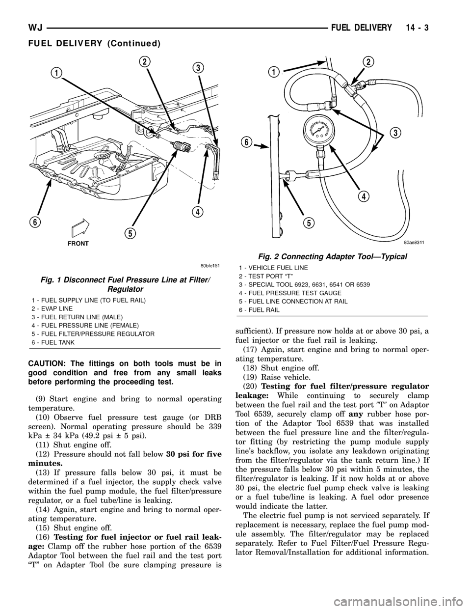
CAUTION: The fittings on both tools must be in
good condition and free from any small leaks
before performing the proceeding test.
(9) Start engine and bring to normal operating
temperature.
(10) Observe fuel pressure test gauge (or DRB
screen). Normal operating pressure should be 339
kPa 34 kPa (49.2 psi 5 psi).
(11) Shut engine off.
(12) Pressure should not fall below30 psi for five
minutes.
(13) If pressure falls below 30 psi, it must be
determined if a fuel injector, the supply check valve
within the fuel pump module, the fuel filter/pressure
regulator, or a fuel tube/line is leaking.
(14) Again, start engine and bring to normal oper-
ating temperature.
(15) Shut engine off.
(16)Testing for fuel injector or fuel rail leak-
age:Clamp off the rubber hose portion of the 6539
Adaptor Tool between the fuel rail and the test port
ªTº on Adapter Tool (be sure clamping pressure issufficient). If pressure now holds at or above 30 psi, a
fuel injector or the fuel rail is leaking.
(17) Again, start engine and bring to normal oper-
ating temperature.
(18) Shut engine off.
(19) Raise vehicle.
(20)Testing for fuel filter/pressure regulator
leakage:While continuing to securely clamp
between the fuel rail and the test port9T9on Adaptor
Tool 6539, securely clamp offanyrubber hose por-
tion of the Adaptor Tool 6539 that was installed
between the fuel pressure line and the filter/regula-
tor fitting (by restricting the pump module supply
line's backflow, you isolate any leakdown originating
from the filter/regulator via the tank return line.) If
the pressure falls below 30 psi within 5 minutes, the
filter/regulator is leaking. If it now holds at or above
30 psi, the electric fuel pump check valve is leaking
or a fuel tube/line is leaking. A fuel odor presence
would indicate the latter.
The electric fuel pump is not serviced separately. If
replacement is necessary, replace the fuel pump mod-
ule assembly. The filter/regulator may be replaced
separately. Refer to Fuel Filter/Fuel Pressure Regu-
lator Removal/Installation for additional information.
Fig. 1 Disconnect Fuel Pressure Line at Filter/
Regulator
1 - FUEL SUPPLY LINE (TO FUEL RAIL)
2 - EVAP LINE
3 - FUEL RETURN LINE (MALE)
4 - FUEL PRESSURE LINE (FEMALE)
5 - FUEL FILTER/PRESSURE REGULATOR
6 - FUEL TANK
Fig. 2 Connecting Adapter ToolÐTypical
1 - VEHICLE FUEL LINE
2 - TEST PORT ªTº
3 - SPECIAL TOOL 6923, 6631, 6541 OR 6539
4 - FUEL PRESSURE TEST GAUGE
5 - FUEL LINE CONNECTION AT RAIL
6 - FUEL RAIL
WJFUEL DELIVERY 14 - 3
FUEL DELIVERY (Continued)
Page 1425 of 2199
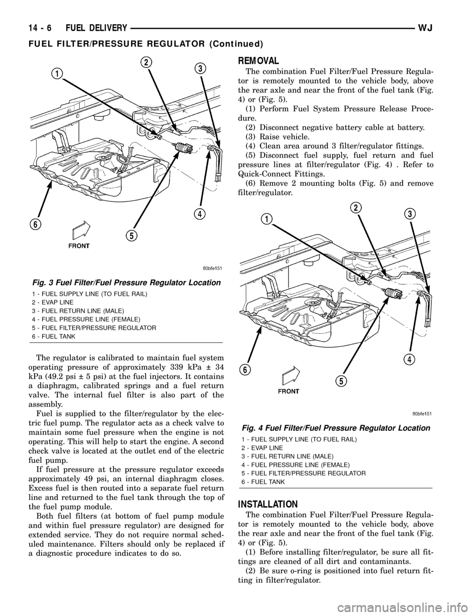
The regulator is calibrated to maintain fuel system
operating pressure of approximately 339 kPa 34
kPa (49.2 psi 5 psi) at the fuel injectors. It contains
a diaphragm, calibrated springs and a fuel return
valve. The internal fuel filter is also part of the
assembly.
Fuel is supplied to the filter/regulator by the elec-
tric fuel pump. The regulator acts as a check valve to
maintain some fuel pressure when the engine is not
operating. This will help to start the engine. A second
check valve is located at the outlet end of the electric
fuel pump.
If fuel pressure at the pressure regulator exceeds
approximately 49 psi, an internal diaphragm closes.
Excess fuel is then routed into a separate fuel return
line and returned to the fuel tank through the top of
the fuel pump module.
Both fuel filters (at bottom of fuel pump module
and within fuel pressure regulator) are designed for
extended service. They do not require normal sched-
uled maintenance. Filters should only be replaced if
a diagnostic procedure indicates to do so.
REMOVAL
The combination Fuel Filter/Fuel Pressure Regula-
tor is remotely mounted to the vehicle body, above
the rear axle and near the front of the fuel tank (Fig.
4) or (Fig. 5).
(1) Perform Fuel System Pressure Release Proce-
dure.
(2) Disconnect negative battery cable at battery.
(3) Raise vehicle.
(4) Clean area around 3 filter/regulator fittings.
(5) Disconnect fuel supply, fuel return and fuel
pressure lines at filter/regulator (Fig. 4) . Refer to
Quick-Connect Fittings.
(6) Remove 2 mounting bolts (Fig. 5) and remove
filter/regulator.
INSTALLATION
The combination Fuel Filter/Fuel Pressure Regula-
tor is remotely mounted to the vehicle body, above
the rear axle and near the front of the fuel tank (Fig.
4) or (Fig. 5).
(1) Before installing filter/regulator, be sure all fit-
tings are cleaned of all dirt and contaminants.
(2) Be sure o-ring is positioned into fuel return fit-
ting in filter/regulator.
Fig. 3 Fuel Filter/Fuel Pressure Regulator Location
1 - FUEL SUPPLY LINE (TO FUEL RAIL)
2 - EVAP LINE
3 - FUEL RETURN LINE (MALE)
4 - FUEL PRESSURE LINE (FEMALE)
5 - FUEL FILTER/PRESSURE REGULATOR
6 - FUEL TANK
Fig. 4 Fuel Filter/Fuel Pressure Regulator Location
1 - FUEL SUPPLY LINE (TO FUEL RAIL)
2 - EVAP LINE
3 - FUEL RETURN LINE (MALE)
4 - FUEL PRESSURE LINE (FEMALE)
5 - FUEL FILTER/PRESSURE REGULATOR
6 - FUEL TANK
14 - 6 FUEL DELIVERYWJ
FUEL FILTER/PRESSURE REGULATOR (Continued)
Page 1426 of 2199
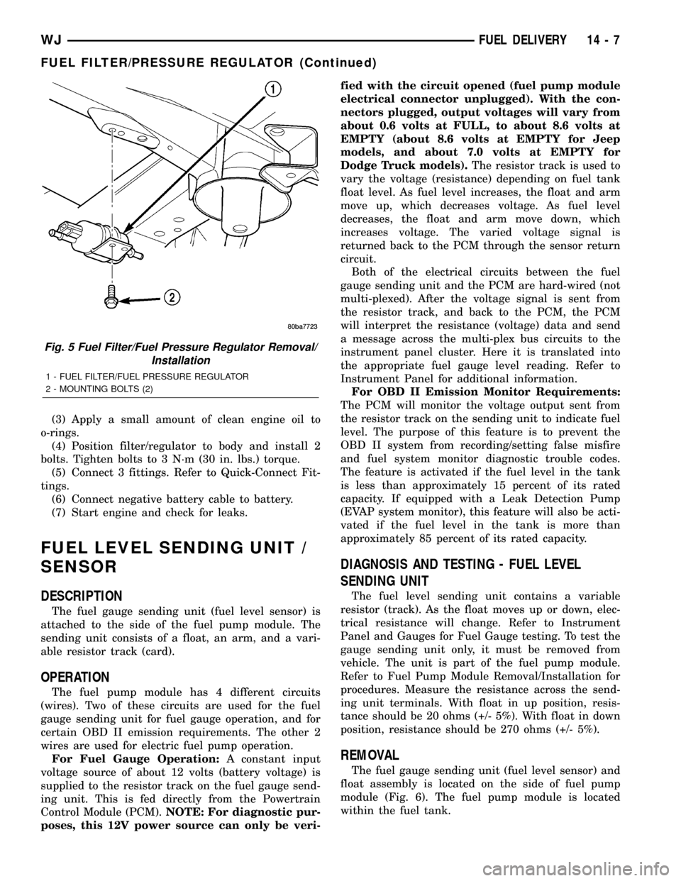
(3) Apply a small amount of clean engine oil to
o-rings.
(4) Position filter/regulator to body and install 2
bolts. Tighten bolts to 3 N´m (30 in. lbs.) torque.
(5) Connect 3 fittings. Refer to Quick-Connect Fit-
tings.
(6) Connect negative battery cable to battery.
(7) Start engine and check for leaks.
FUEL LEVEL SENDING UNIT /
SENSOR
DESCRIPTION
The fuel gauge sending unit (fuel level sensor) is
attached to the side of the fuel pump module. The
sending unit consists of a float, an arm, and a vari-
able resistor track (card).
OPERATION
The fuel pump module has 4 different circuits
(wires). Two of these circuits are used for the fuel
gauge sending unit for fuel gauge operation, and for
certain OBD II emission requirements. The other 2
wires are used for electric fuel pump operation.
For Fuel Gauge Operation:A constant input
voltage source of about 12 volts (battery voltage) is
supplied to the resistor track on the fuel gauge send-
ing unit. This is fed directly from the Powertrain
Control Module (PCM).NOTE: For diagnostic pur-
poses, this 12V power source can only be veri-fied with the circuit opened (fuel pump module
electrical connector unplugged). With the con-
nectors plugged, output voltages will vary from
about 0.6 volts at FULL, to about 8.6 volts at
EMPTY (about 8.6 volts at EMPTY for Jeep
models, and about 7.0 volts at EMPTY for
Dodge Truck models).The resistor track is used to
vary the voltage (resistance) depending on fuel tank
float level. As fuel level increases, the float and arm
move up, which decreases voltage. As fuel level
decreases, the float and arm move down, which
increases voltage. The varied voltage signal is
returned back to the PCM through the sensor return
circuit.
Both of the electrical circuits between the fuel
gauge sending unit and the PCM are hard-wired (not
multi-plexed). After the voltage signal is sent from
the resistor track, and back to the PCM, the PCM
will interpret the resistance (voltage) data and send
a message across the multi-plex bus circuits to the
instrument panel cluster. Here it is translated into
the appropriate fuel gauge level reading. Refer to
Instrument Panel for additional information.
For OBD II Emission Monitor Requirements:
The PCM will monitor the voltage output sent from
the resistor track on the sending unit to indicate fuel
level. The purpose of this feature is to prevent the
OBD II system from recording/setting false misfire
and fuel system monitor diagnostic trouble codes.
The feature is activated if the fuel level in the tank
is less than approximately 15 percent of its rated
capacity. If equipped with a Leak Detection Pump
(EVAP system monitor), this feature will also be acti-
vated if the fuel level in the tank is more than
approximately 85 percent of its rated capacity.
DIAGNOSIS AND TESTING - FUEL LEVEL
SENDING UNIT
The fuel level sending unit contains a variable
resistor (track). As the float moves up or down, elec-
trical resistance will change. Refer to Instrument
Panel and Gauges for Fuel Gauge testing. To test the
gauge sending unit only, it must be removed from
vehicle. The unit is part of the fuel pump module.
Refer to Fuel Pump Module Removal/Installation for
procedures. Measure the resistance across the send-
ing unit terminals. With float in up position, resis-
tance should be 20 ohms (+/- 5%). With float in down
position, resistance should be 270 ohms (+/- 5%).
REMOVAL
The fuel gauge sending unit (fuel level sensor) and
float assembly is located on the side of fuel pump
module (Fig. 6). The fuel pump module is located
within the fuel tank.
Fig. 5 Fuel Filter/Fuel Pressure Regulator Removal/
Installation
1 - FUEL FILTER/FUEL PRESSURE REGULATOR
2 - MOUNTING BOLTS (2)
WJFUEL DELIVERY 14 - 7
FUEL FILTER/PRESSURE REGULATOR (Continued)