Specifications JEEP GRAND CHEROKEE 2002 WJ / 2.G Workshop Manual
[x] Cancel search | Manufacturer: JEEP, Model Year: 2002, Model line: GRAND CHEROKEE, Model: JEEP GRAND CHEROKEE 2002 WJ / 2.GPages: 2199, PDF Size: 76.01 MB
Page 1867 of 2199
DIAGNOSIS AND TESTING
DIAGNOSIS AND TESTING - PRESSURE
GAUGES
A quality air pressure gauge is recommended to
check tire pressure. After checking the air pressure,
replace valve cap finger tight.
DIAGNOSIS AND TESTING - TREAD WEAR
INDICATORS
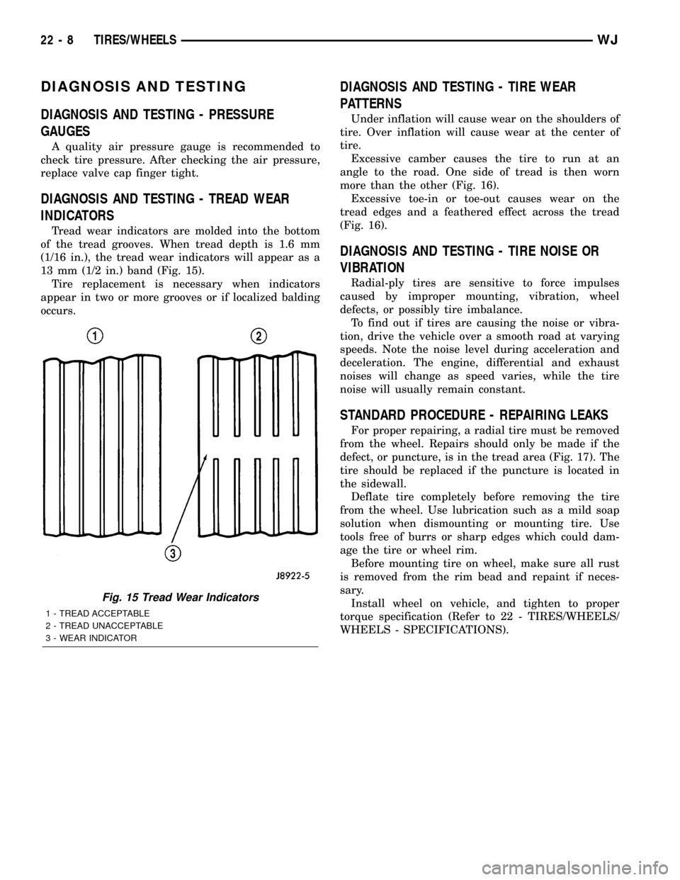
Tread wear indicators are molded into the bottom
of the tread grooves. When tread depth is 1.6 mm
(1/16 in.), the tread wear indicators will appear as a
13 mm (1/2 in.) band (Fig. 15).
Tire replacement is necessary when indicators
appear in two or more grooves or if localized balding
occurs.
DIAGNOSIS AND TESTING - TIRE WEAR
PATTERNS
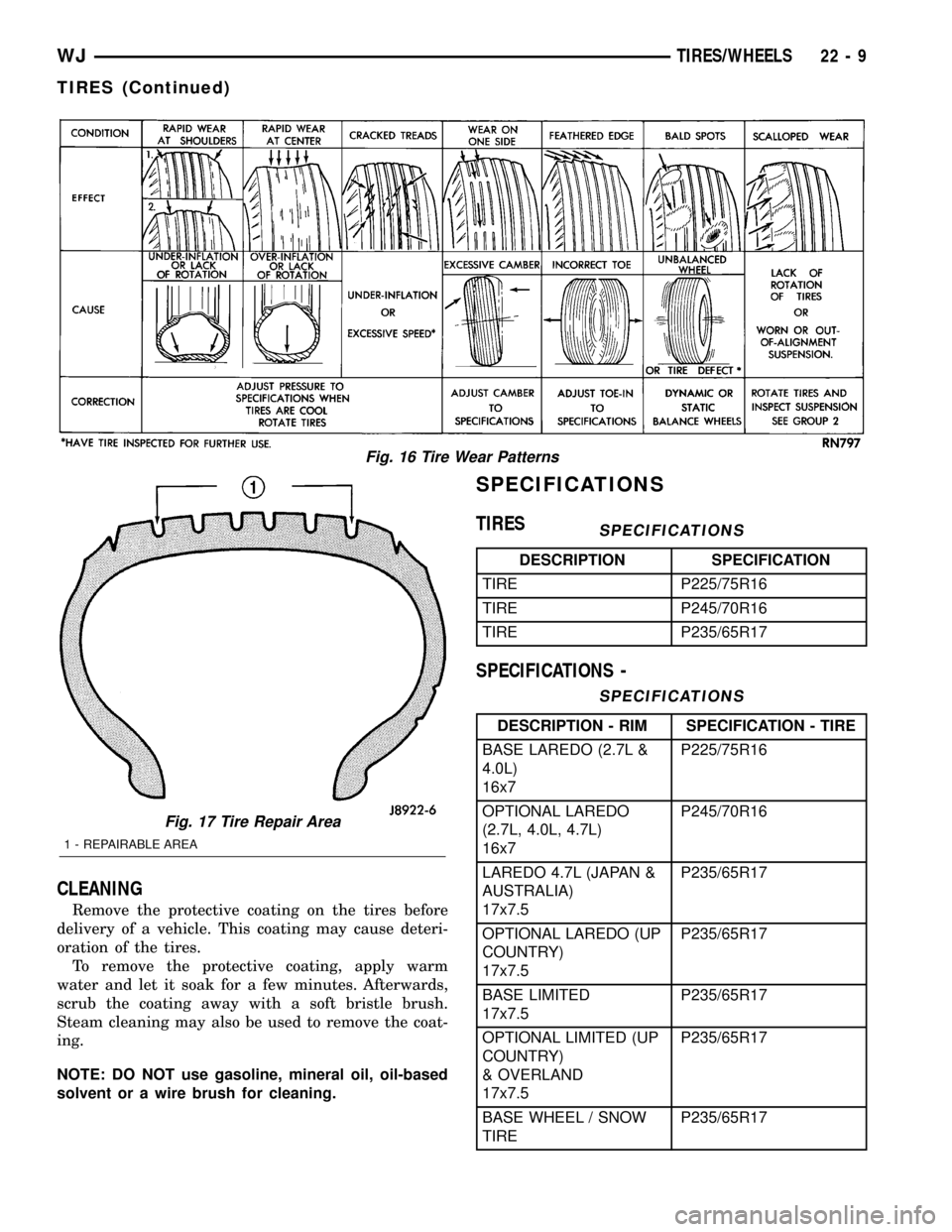
Under inflation will cause wear on the shoulders of
tire. Over inflation will cause wear at the center of
tire.
Excessive camber causes the tire to run at an
angle to the road. One side of tread is then worn
more than the other (Fig. 16).
Excessive toe-in or toe-out causes wear on the
tread edges and a feathered effect across the tread
(Fig. 16).
DIAGNOSIS AND TESTING - TIRE NOISE OR
VIBRATION
Radial-ply tires are sensitive to force impulses
caused by improper mounting, vibration, wheel
defects, or possibly tire imbalance.
To find out if tires are causing the noise or vibra-
tion, drive the vehicle over a smooth road at varying
speeds. Note the noise level during acceleration and
deceleration. The engine, differential and exhaust
noises will change as speed varies, while the tire
noise will usually remain constant.
STANDARD PROCEDURE - REPAIRING LEAKS
For proper repairing, a radial tire must be removed
from the wheel. Repairs should only be made if the
defect, or puncture, is in the tread area (Fig. 17). The
tire should be replaced if the puncture is located in
the sidewall.
Deflate tire completely before removing the tire
from the wheel. Use lubrication such as a mild soap
solution when dismounting or mounting tire. Use
tools free of burrs or sharp edges which could dam-
age the tire or wheel rim.
Before mounting tire on wheel, make sure all rust
is removed from the rim bead and repaint if neces-
sary.
Install wheel on vehicle, and tighten to proper
torque specification (Refer to 22 - TIRES/WHEELS/
WHEELS - SPECIFICATIONS).
Fig. 15 Tread Wear Indicators
1 - TREAD ACCEPTABLE
2 - TREAD UNACCEPTABLE
3 - WEAR INDICATOR
22 - 8 TIRES/WHEELSWJ
Page 1868 of 2199
CLEANING
Remove the protective coating on the tires before
delivery of a vehicle. This coating may cause deteri-
oration of the tires.
To remove the protective coating, apply warm
water and let it soak for a few minutes. Afterwards,
scrub the coating away with a soft bristle brush.
Steam cleaning may also be used to remove the coat-
ing.
NOTE: DO NOT use gasoline, mineral oil, oil-based
solvent or a wire brush for cleaning.
SPECIFICATIONS
TIRES
SPECIFICATIONS
DESCRIPTION SPECIFICATION
TIRE P225/75R16
TIRE P245/70R16
TIRE P235/65R17
SPECIFICATIONS -
SPECIFICATIONS
DESCRIPTION - RIM SPECIFICATION - TIRE
BASE LAREDO (2.7L &
4.0L)
16x7P225/75R16
OPTIONAL LAREDO
(2.7L, 4.0L, 4.7L)
16x7P245/70R16
LAREDO 4.7L (JAPAN &
AUSTRALIA)
17x7.5P235/65R17
OPTIONAL LAREDO (UP
COUNTRY)
17x7.5P235/65R17
BASE LIMITED
17x7.5P235/65R17
OPTIONAL LIMITED (UP
COUNTRY)
& OVERLAND
17x7.5P235/65R17
BASE WHEEL / SNOW
TIREP235/65R17
Fig. 16 Tire Wear Patterns
Fig. 17 Tire Repair Area
1 - REPAIRABLE AREA
WJTIRES/WHEELS 22 - 9
TIRES (Continued)
Page 1870 of 2199
²Bent or dented
²Leak air through welds
²Have damaged bolt holes
Wheel repairs employing hammering, heating, or
welding are not allowed.
Original equipment wheels are available through
your dealer. Replacement wheels from any other
source should be equivalent in:
²Load carrying capacity
²Diameter
²Width²Offset
²Mounting configuration
Failure to use equivalent replacement wheels may
affect the safety and handling of your vehicle.
Replacement withusedwheels is not recommended.
Their service history may have included severe treat-
ment.
SPECIFICATIONS
TORQUE CHART
TORQUE SPECIFICATIONS
DESCRIPTION N´m Ft. Lbs. In. Lbs.
Lug Nut
1/2 X 20 with 60É Cone115-150 85-115 Ð
STUDS
REMOVAL
CAUTION: Do not use a hammer to remove wheel
studs.
(1) Raise and support vehicle.
(2) Remove wheel and tire assembly.
(3) Remove brake caliper, caliper adapter and
rotor,(Refer to 5 - BRAKES/HYDRAULIC/MECHAN-
ICAL/ROTORS - REMOVAL).
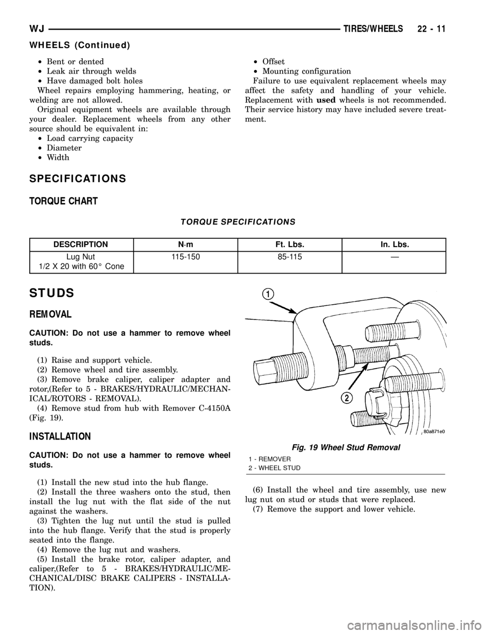
(4) Remove stud from hub with Remover C-4150A
(Fig. 19).
INSTALLATION
CAUTION: Do not use a hammer to remove wheel
studs.
(1) Install the new stud into the hub flange.
(2) Install the three washers onto the stud, then
install the lug nut with the flat side of the nut
against the washers.
(3) Tighten the lug nut until the stud is pulled
into the hub flange. Verify that the stud is properly
seated into the flange.
(4) Remove the lug nut and washers.
(5) Install the brake rotor, caliper adapter, and
caliper,(Refer to 5 - BRAKES/HYDRAULIC/ME-
CHANICAL/DISC BRAKE CALIPERS - INSTALLA-
TION).(6) Install the wheel and tire assembly, use new
lug nut on stud or studs that were replaced.
(7) Remove the support and lower vehicle.Fig. 19 Wheel Stud Removal
1 - REMOVER
2 - WHEEL STUD
WJTIRES/WHEELS 22 - 11
WHEELS (Continued)
Page 1874 of 2199
BODY
TABLE OF CONTENTS
page page
BODY
DIAGNOSIS AND TESTING
WATER LEAKS........................1
WIND NOISE..........................2
STANDARD PROCEDURE
STANDARD PROCEDURE - BODY
LUBRICATION.........................2
STANDARD PROCEDURE - DRILLING AND
WELDING............................3
SPECIFICATIONS
BODY LUBRICANTS....................3
SPECIFICATIONS - TORQUE.............4
SPECIAL TOOLS
BODY...............................4DECKLID/HATCH/LIFTGATE/TAILGATE........5
DOOR - FRONT.........................11
DOORS - REAR.........................19
EXTERIOR.............................25
HOOD.................................33
INSTRUMENT PANEL SYSTEM.............36
INTERIOR..............................69
PAINT.................................81
SEATS................................83
STATIONARY GLASS.....................93
SUNROOF.............................96
WEATHERSTRIP/SEALS..................105
BODY STRUCTURE.....................112
BODY
DIAGNOSIS AND TESTING
WATER LEAKS
Water leaks can be caused by poor sealing,
improper body component alignment, body seam
porosity, missing plugs, or blocked drain holes. Cen-
trifugal and gravitational force can cause water to
drip from a location away from the actual leak point,
making leak detection difficult. All body sealing
points should be water tight in normal wet-driving
conditions. Water flowing downward from the front of
the vehicle should not enter the passenger or luggage
compartment. Moving sealing surfaces will not
always seal water tight under all conditions. At
times, side glass or door seals will allow water to
enter the passenger compartment during high pres-
sure washing or hard driving rain (severe) condi-
tions. Overcompensating on door or glass
adjustments to stop a water leak that occurs under
severe conditions can cause premature seal wear and
excessive closing or latching effort. After completing
a repair, water test vehicle to verify leak has stopped
before returning vehicle to use.
VISUAL INSPECTION BEFORE WATER LEAK TESTS
Verify that floor and body plugs are in place, body
drains are clear, and body components are properly
aligned and sealed. If component alignment or seal-
ing is necessary, refer to the appropriate section of
this group for proper procedures.
WATER LEAK TESTS
WARNING: DO NOT USE ELECTRIC SHOP LIGHTS
OR TOOLS IN WATER TEST AREA. PERSONAL
INJURY CAN RESULT.
When the conditions causing a water leak have
been determined, simulate the conditions as closely
as possible.
²If a leak occurs with the vehicle parked in a
steady light rain, flood the leak area with an open-
ended garden hose.
²If a leak occurs while driving at highway speeds
in a steady rain, test the leak area with a reasonable
velocity stream or fan spray of water. Direct the
spray in a direction comparable to actual conditions.
²If a leak occurs when the vehicle is parked on an
incline, hoist the end or side of the vehicle to simu-
late this condition. This method can be used when
the leak occurs when the vehicle accelerates, stops or
turns. If the leak occurs on acceleration, hoist the
front of the vehicle. If the leak occurs when braking,
hoist the back of the vehicle. If the leak occurs on left
turns, hoist the left side of the vehicle. If the leak
occurs on right turns, hoist the right side of the vehi-
cle. For hoisting recommendations refer to Group 0,
Lubrication and Maintenance, General Information
section.
WATER LEAK DETECTION
To detect a water leak point-of-entry, do a water
test and watch for water tracks or droplets forming
on the inside of the vehicle. If necessary, remove inte-
rior trim covers or panels to gain visual access to the
WJBODY 23 - 1
Page 1876 of 2199
(2) Apply silicone lubricant to a cloth and wipe it
on door seals to avoid over-spray that can soil pas-
senger's clothing.
(3) Before applying lubricant, the component
should be wiped clean. After lubrication, any excess
lubricant should be removed.
(4) The hood latch, latch release mechanism, latch
striker, and safety latch should be lubricated period-
ically.
(5) The door lock cylinders should be lubricated
twice each year (preferably autumn and spring).
(a) Spray a small amount of lock cylinder lubri-
cant directly into the lock cylinder.
(b) Apply a small amount to the key and insert
it into the lock cylinder.
(c) Rotate it to the locked position and then back
to the unlocked position several times.(d) Remove the key. Wipe the lubricant from it
with a clean cloth to avoid soiling of clothing.
STANDARD PROCEDURE - DRILLING AND
WELDING
When holes must be drilled or punched in an inner
body panel, verify depth of space to the outer body
panel, electrical wiring, or other components. Dam-
age to vehicle can result.
Do not weld exterior panels unless combustible
material on the interior of vehicle is removed from
the repair area. Fire or hazardous conditions, can
result.
Always have a fire extinguisher ready for use when
welding.
SPECIFICATIONS
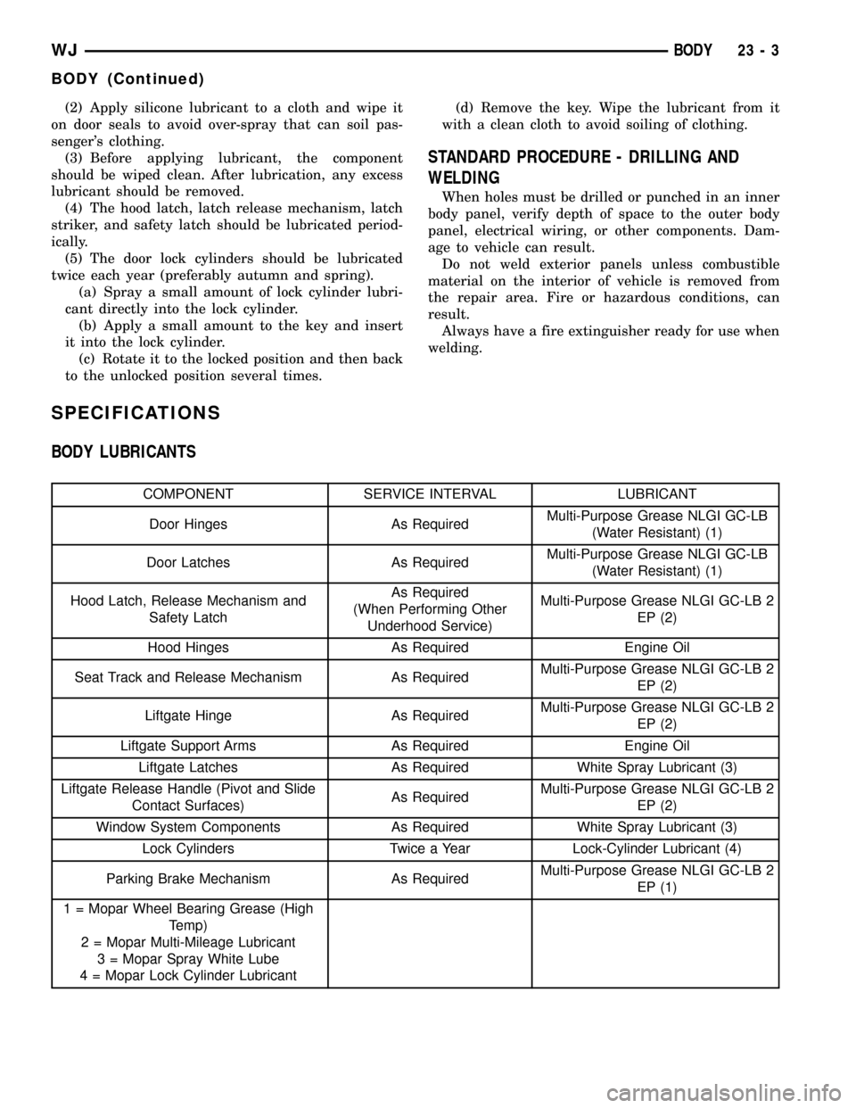
BODY LUBRICANTS
COMPONENT SERVICE INTERVAL LUBRICANT
Door Hinges As RequiredMulti-Purpose Grease NLGI GC-LB
(Water Resistant) (1)
Door Latches As RequiredMulti-Purpose Grease NLGI GC-LB
(Water Resistant) (1)
Hood Latch, Release Mechanism and
Safety LatchAs Required
(When Performing Other
Underhood Service)Multi-Purpose Grease NLGI GC-LB 2
EP (2)
Hood Hinges As Required Engine Oil
Seat Track and Release Mechanism As RequiredMulti-Purpose Grease NLGI GC-LB 2
EP (2)
Liftgate Hinge As RequiredMulti-Purpose Grease NLGI GC-LB 2
EP (2)
Liftgate Support Arms As Required Engine Oil
Liftgate Latches As Required White Spray Lubricant (3)
Liftgate Release Handle (Pivot and Slide
Contact Surfaces)As RequiredMulti-Purpose Grease NLGI GC-LB 2
EP (2)
Window System Components As Required White Spray Lubricant (3)
Lock Cylinders Twice a Year Lock-Cylinder Lubricant (4)
Parking Brake Mechanism As RequiredMulti-Purpose Grease NLGI GC-LB 2
EP (1)
1 = Mopar Wheel Bearing Grease (High
Temp)
2 = Mopar Multi-Mileage Lubricant
3 = Mopar Spray White Lube
4 = Mopar Lock Cylinder Lubricant
WJBODY 23 - 3
BODY (Continued)
Page 1877 of 2199
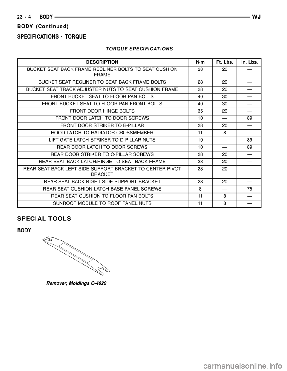
SPECIFICATIONS - TORQUE
TORQUE SPECIFICATIONS
DESCRIPTION N´m Ft. Lbs. In. Lbs.
BUCKET SEAT BACK FRAME RECLINER BOLTS TO SEAT CUSHION
FRAME28 20 Ð
BUCKET SEAT RECLINER TO SEAT BACK FRAME BOLTS 28 20 Ð
BUCKET SEAT TRACK ADJUSTER NUTS TO SEAT CUSHION FRAME 28 20 Ð
FRONT BUCKET SEAT TO FLOOR PAN BOLTS 40 30 Ð
FRONT BUCKET SEAT TO FLOOR PAN FRONT BOLTS 40 30 Ð
FRONT DOOR HINGE BOLTS 35 26 Ð
FRONT DOOR LATCH TO DOOR SCREWS 10 Ð 89
FRONT DOOR STRIKER TO B-PILLAR 28 20 Ð
HOOD LATCH TO RADIATOR CROSSMEMBER 11 8 Ð
LIFT GATE LATCH STRIKER TO D-PILLAR NUTS 10 Ð 89
REAR DOOR LATCH TO DOOR SCREWS 10 Ð 89
REAR DOOR STRIKER TO C-PILLAR SCREWS 28 20 Ð
REAR SEAT BACK LATCH/HINGE TO SEAT BACK FRAME 28 20 Ð
REAR SEAT BACK LEFT SIDE SUPPORT BRACKET TO CENTER PIVOT
BRACKET28 20 Ð
REAR SEAT BACK RIGHT SIDE SUPPORT BRACKET 28 20 Ð
REAR SEAT CUSHION LATCH BASE PANEL SCREWS 8 Ð 75
REAR SEAT CUSHION TO FLOOR PAN BOLTS 11 8 Ð
SUNROOF MODULE TO ROOF PANEL NUTS 11 8 Ð
SPECIAL TOOLS
BODY
Remover, Moldings C-4829
23 - 4 BODYWJ
BODY (Continued)
Page 1954 of 2199
PAINT
TABLE OF CONTENTS
page page
PAINT
SPECIFICATIONS - PAINT CODES..........81
PAINT CODE
DESCRIPTION.........................81
BASE COAT/CLEAR COAT FINISH
DESCRIPTION.........................81PAINT TOUCH-UP
DESCRIPTION.........................82
FINESSE SANDING/BUFFING & POLISHING
DESCRIPTION.........................82
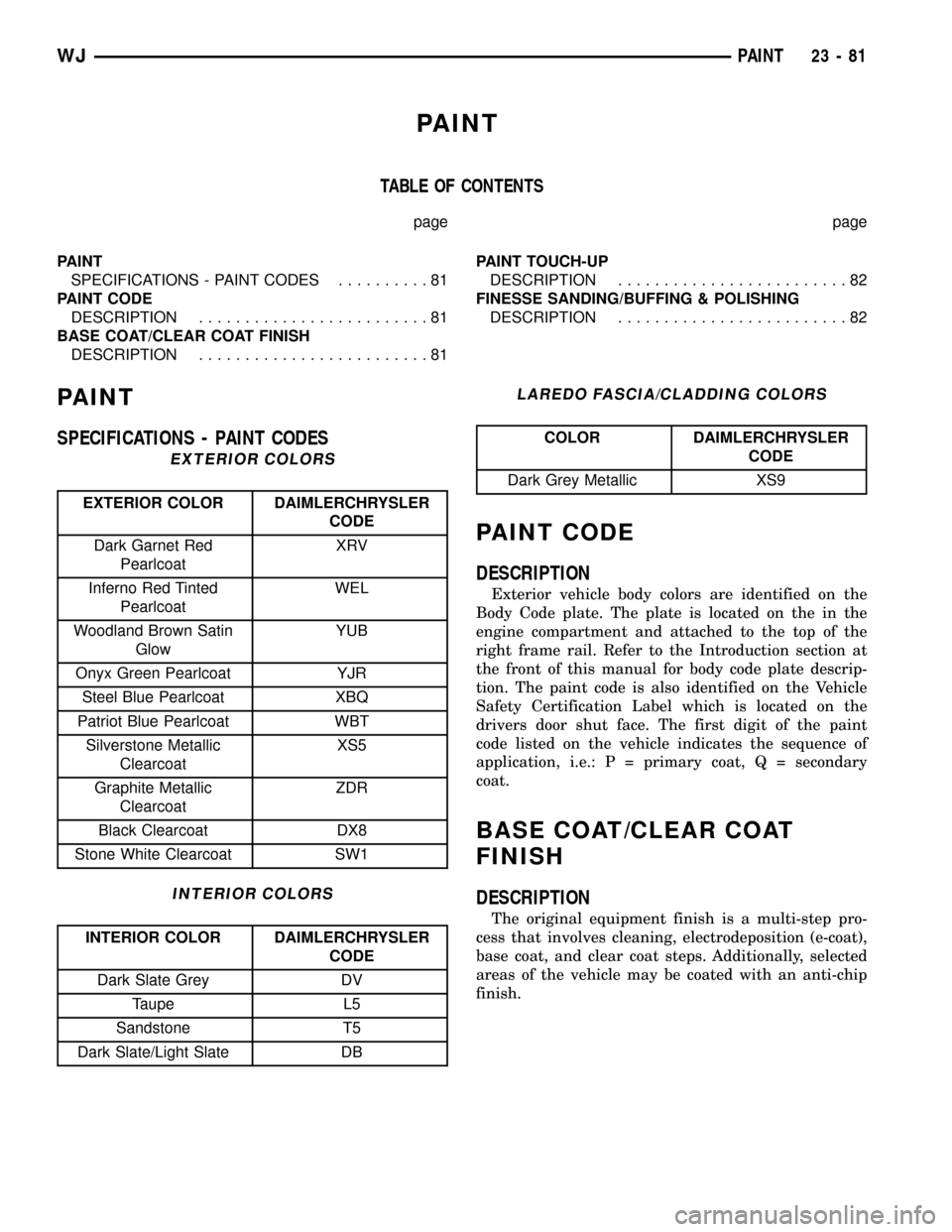
PAINT
SPECIFICATIONS - PAINT CODES
EXTERIOR COLORS
EXTERIOR COLOR DAIMLERCHRYSLER
CODE
Dark Garnet Red
PearlcoatXRV
Inferno Red Tinted
PearlcoatWEL
Woodland Brown Satin
GlowYUB
Onyx Green Pearlcoat YJR
Steel Blue Pearlcoat XBQ
Patriot Blue Pearlcoat WBT
Silverstone Metallic
ClearcoatXS5
Graphite Metallic
ClearcoatZDR
Black Clearcoat DX8
Stone White Clearcoat SW1
INTERIOR COLORS
INTERIOR COLOR DAIMLERCHRYSLER
CODE
Dark Slate Grey DV
Taupe L5
Sandstone T5
Dark Slate/Light Slate DB
LAREDO FASCIA/CLADDING COLORS
COLOR DAIMLERCHRYSLER
CODE
Dark Grey Metallic XS9
PAINT CODE
DESCRIPTION
Exterior vehicle body colors are identified on the
Body Code plate. The plate is located on the in the
engine compartment and attached to the top of the
right frame rail. Refer to the Introduction section at
the front of this manual for body code plate descrip-
tion. The paint code is also identified on the Vehicle
Safety Certification Label which is located on the
drivers door shut face. The first digit of the paint
code listed on the vehicle indicates the sequence of
application, i.e.: P = primary coat, Q = secondary
coat.
BASE COAT/CLEAR COAT
FINISH
DESCRIPTION
The original equipment finish is a multi-step pro-
cess that involves cleaning, electrodeposition (e-coat),
base coat, and clear coat steps. Additionally, selected
areas of the vehicle may be coated with an anti-chip
finish.
WJPAINT 23 - 81
Page 1984 of 2199
BODY STRUCTURE
TABLE OF CONTENTS
page page
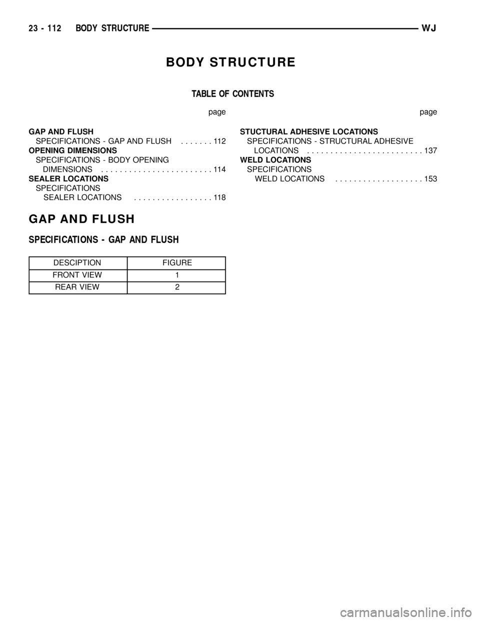
GAP AND FLUSH
SPECIFICATIONS - GAP AND FLUSH.......112
OPENING DIMENSIONS
SPECIFICATIONS - BODY OPENING
DIMENSIONS........................114
SEALER LOCATIONS
SPECIFICATIONS
SEALER LOCATIONS.................118STUCTURAL ADHESIVE LOCATIONS
SPECIFICATIONS - STRUCTURAL ADHESIVE
LOCATIONS.........................137
WELD LOCATIONS
SPECIFICATIONS
WELD LOCATIONS...................153
GAP AND FLUSH
SPECIFICATIONS - GAP AND FLUSH
DESCIPTION FIGURE
FRONT VIEW 1
REAR VIEW 2
23 - 112 BODY STRUCTUREWJ
Page 1987 of 2199
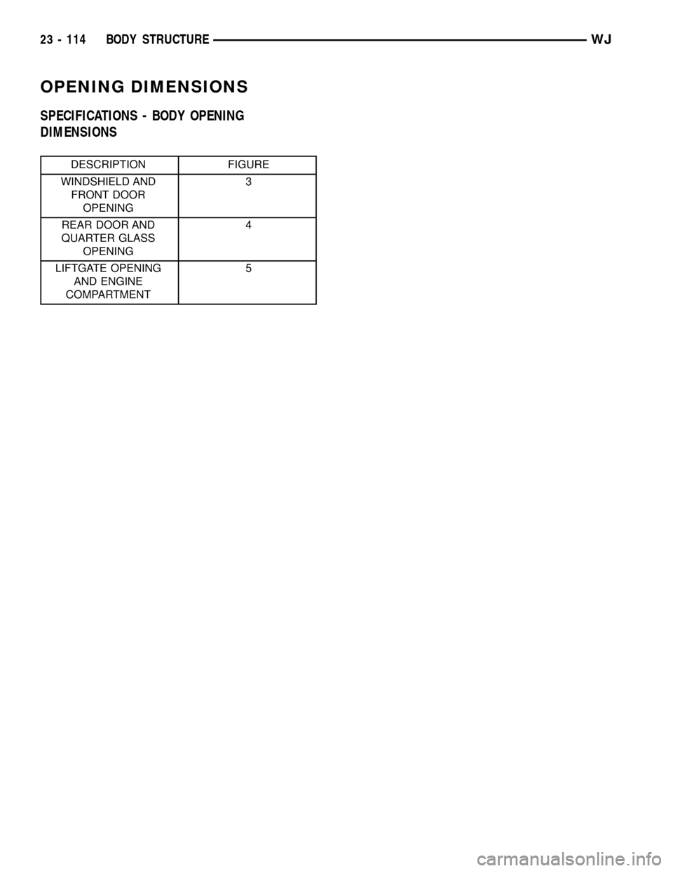
OPENING DIMENSIONS
SPECIFICATIONS - BODY OPENING
DIMENSIONS
DESCRIPTION FIGURE
WINDSHIELD AND
FRONT DOOR
OPENING3
REAR DOOR AND
QUARTER GLASS
OPENING4
LIFTGATE OPENING
AND ENGINE
COMPARTMENT5
23 - 114 BODY STRUCTUREWJ
Page 1991 of 2199
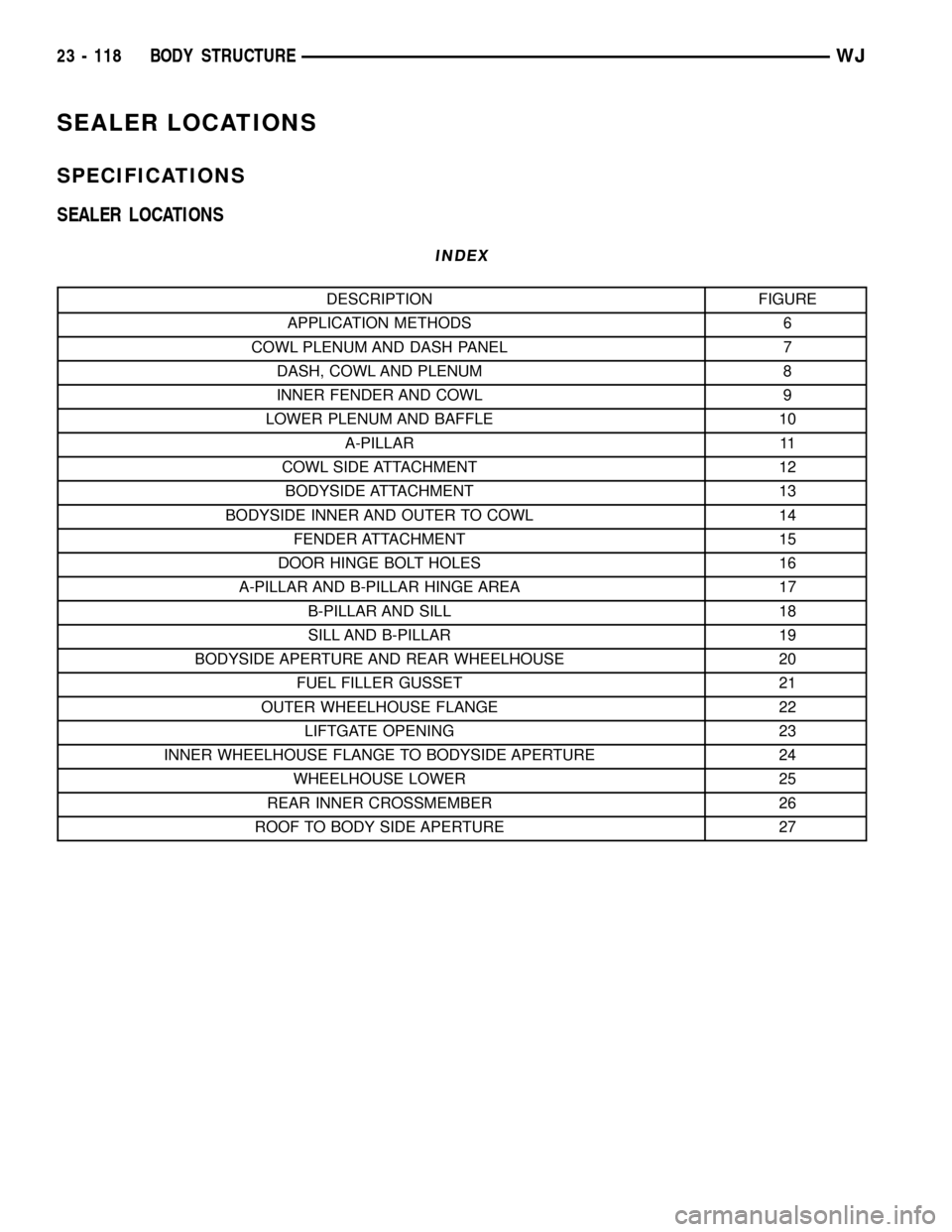
SEALER LOCATIONS
SPECIFICATIONS
SEALER LOCATIONS
INDEX
DESCRIPTION FIGURE
APPLICATION METHODS 6
COWL PLENUM AND DASH PANEL 7
DASH, COWL AND PLENUM 8
INNER FENDER AND COWL 9
LOWER PLENUM AND BAFFLE 10
A-PILLAR 11
COWL SIDE ATTACHMENT 12
BODYSIDE ATTACHMENT 13
BODYSIDE INNER AND OUTER TO COWL 14
FENDER ATTACHMENT 15
DOOR HINGE BOLT HOLES 16
A-PILLAR AND B-PILLAR HINGE AREA 17
B-PILLAR AND SILL 18
SILL AND B-PILLAR 19
BODYSIDE APERTURE AND REAR WHEELHOUSE 20
FUEL FILLER GUSSET 21
OUTER WHEELHOUSE FLANGE 22
LIFTGATE OPENING 23
INNER WHEELHOUSE FLANGE TO BODYSIDE APERTURE 24
WHEELHOUSE LOWER 25
REAR INNER CROSSMEMBER 26
ROOF TO BODY SIDE APERTURE 27
23 - 118 BODY STRUCTUREWJ