Specifications JEEP GRAND CHEROKEE 2002 WJ / 2.G Workshop Manual
[x] Cancel search | Manufacturer: JEEP, Model Year: 2002, Model line: GRAND CHEROKEE, Model: JEEP GRAND CHEROKEE 2002 WJ / 2.GPages: 2199, PDF Size: 76.01 MB
Page 2010 of 2199
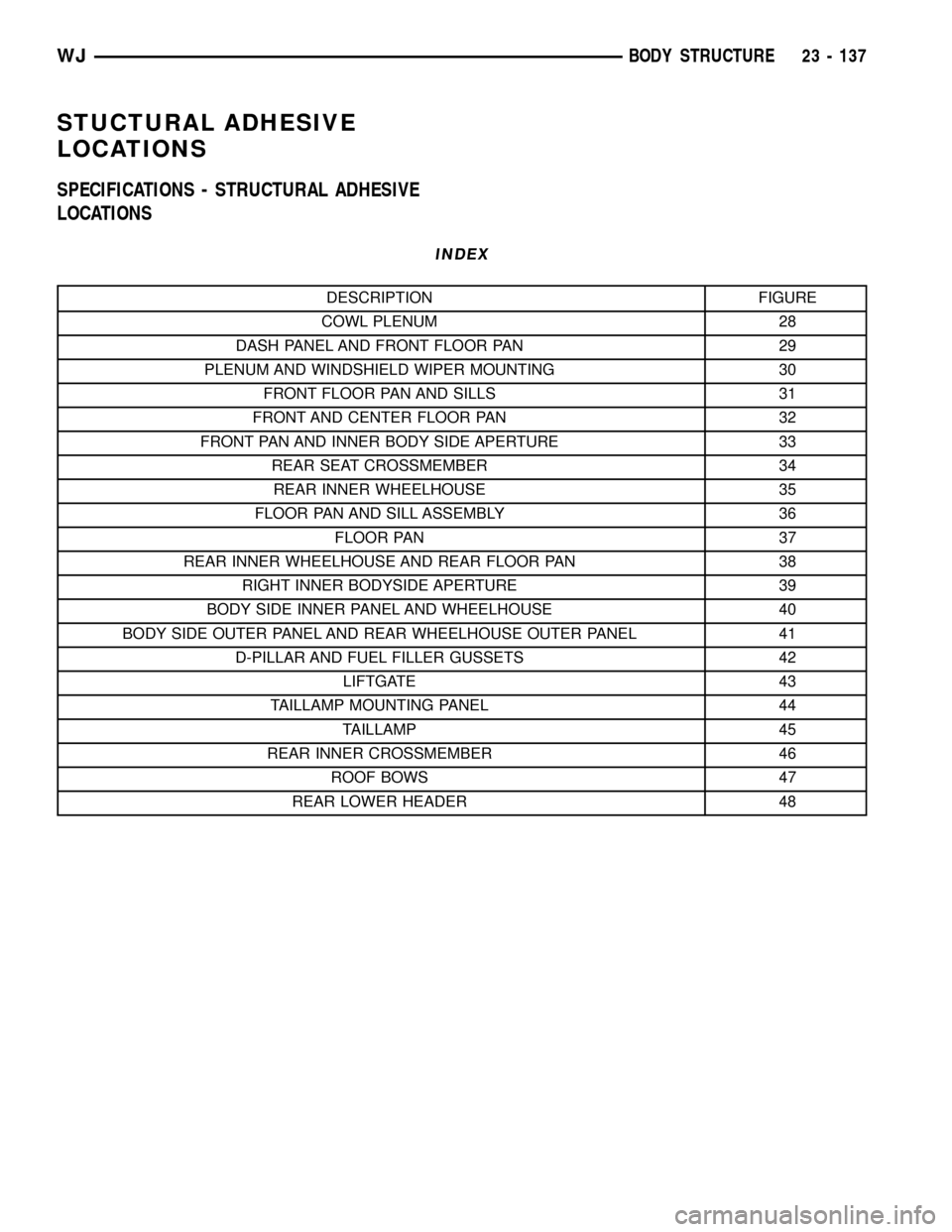
STUCTURAL ADHESIVE
LOCATIONS
SPECIFICATIONS - STRUCTURAL ADHESIVE
LOCATIONS
INDEX
DESCRIPTION FIGURE
COWL PLENUM 28
DASH PANEL AND FRONT FLOOR PAN 29
PLENUM AND WINDSHIELD WIPER MOUNTING 30
FRONT FLOOR PAN AND SILLS 31
FRONT AND CENTER FLOOR PAN 32
FRONT PAN AND INNER BODY SIDE APERTURE 33
REAR SEAT CROSSMEMBER 34
REAR INNER WHEELHOUSE 35
FLOOR PAN AND SILL ASSEMBLY 36
FLOOR PAN 37
REAR INNER WHEELHOUSE AND REAR FLOOR PAN 38
RIGHT INNER BODYSIDE APERTURE 39
BODY SIDE INNER PANEL AND WHEELHOUSE 40
BODY SIDE OUTER PANEL AND REAR WHEELHOUSE OUTER PANEL 41
D-PILLAR AND FUEL FILLER GUSSETS 42
LIFTGATE 43
TAILLAMP MOUNTING PANEL 44
TAILLAMP 45
REAR INNER CROSSMEMBER 46
ROOF BOWS 47
REAR LOWER HEADER 48
WJBODY STRUCTURE 23 - 137
Page 2026 of 2199
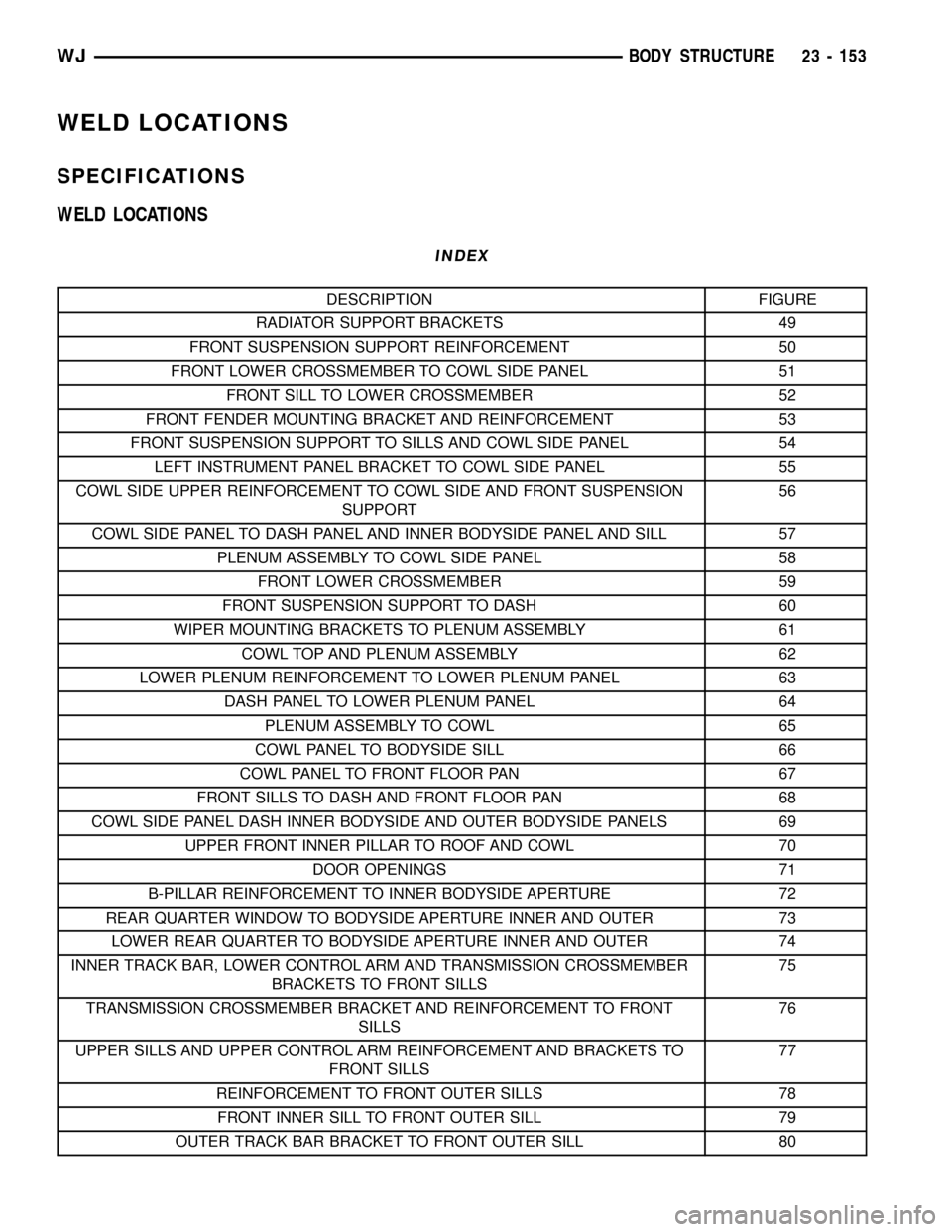
WELD LOCATIONS
SPECIFICATIONS
WELD LOCATIONS
INDEX
DESCRIPTION FIGURE
RADIATOR SUPPORT BRACKETS 49
FRONT SUSPENSION SUPPORT REINFORCEMENT 50
FRONT LOWER CROSSMEMBER TO COWL SIDE PANEL 51
FRONT SILL TO LOWER CROSSMEMBER 52
FRONT FENDER MOUNTING BRACKET AND REINFORCEMENT 53
FRONT SUSPENSION SUPPORT TO SILLS AND COWL SIDE PANEL 54
LEFT INSTRUMENT PANEL BRACKET TO COWL SIDE PANEL 55
COWL SIDE UPPER REINFORCEMENT TO COWL SIDE AND FRONT SUSPENSION
SUPPORT56
COWL SIDE PANEL TO DASH PANEL AND INNER BODYSIDE PANEL AND SILL 57
PLENUM ASSEMBLY TO COWL SIDE PANEL 58
FRONT LOWER CROSSMEMBER 59
FRONT SUSPENSION SUPPORT TO DASH 60
WIPER MOUNTING BRACKETS TO PLENUM ASSEMBLY 61
COWL TOP AND PLENUM ASSEMBLY 62
LOWER PLENUM REINFORCEMENT TO LOWER PLENUM PANEL 63
DASH PANEL TO LOWER PLENUM PANEL 64
PLENUM ASSEMBLY TO COWL 65
COWL PANEL TO BODYSIDE SILL 66
COWL PANEL TO FRONT FLOOR PAN 67
FRONT SILLS TO DASH AND FRONT FLOOR PAN 68
COWL SIDE PANEL DASH INNER BODYSIDE AND OUTER BODYSIDE PANELS 69
UPPER FRONT INNER PILLAR TO ROOF AND COWL 70
DOOR OPENINGS 71
B-PILLAR REINFORCEMENT TO INNER BODYSIDE APERTURE 72
REAR QUARTER WINDOW TO BODYSIDE APERTURE INNER AND OUTER 73
LOWER REAR QUARTER TO BODYSIDE APERTURE INNER AND OUTER 74
INNER TRACK BAR, LOWER CONTROL ARM AND TRANSMISSION CROSSMEMBER
BRACKETS TO FRONT SILLS75
TRANSMISSION CROSSMEMBER BRACKET AND REINFORCEMENT TO FRONT
SILLS76
UPPER SILLS AND UPPER CONTROL ARM REINFORCEMENT AND BRACKETS TO
FRONT SILLS77
REINFORCEMENT TO FRONT OUTER SILLS 78
FRONT INNER SILL TO FRONT OUTER SILL 79
OUTER TRACK BAR BRACKET TO FRONT OUTER SILL 80
WJBODY STRUCTURE 23 - 153
Page 2078 of 2199

HEATING & AIR CONDITIONING
TABLE OF CONTENTS
page page
HEATING & AIR CONDITIONING
DESCRIPTION
DESCRIPTION - COOLING SYSTEM
REQUIREMENTS.......................1
DESCRIPTION - HEATER AND AIR
CONDITIONER........................1
DESCRIPTION - REFRIGERANT SYSTEM
SERVICE PORT........................1
OPERATION
OPERATION - HEATER AND AIR
CONDITIONER........................2
OPERATION - REFRIGERANT SYSTEM
SERVICE PORT........................2DIAGNOSIS AND TESTING
DIAGNOSIS AND TESTING - A/C
PERFORMANCE.......................2
DIAGNOSIS AND TESTING - HEATER
PERFORMANCE.......................6
STANDARD PROCEDURE - DIODE
REPLACEMENT.......................6
SPECIFICATIONS
A/C APPLICATION TABLE................7
TORQUE SPECIFICATIONS..............8
CONTROLS.............................9
DISTRIBUTION..........................36
PLUMBING.............................51
HEATING & AIR
CONDITIONING
DESCRIPTION
DESCRIPTION - COOLING SYSTEM
REQUIREMENTS
To maintain the performance level of the heating-
air conditioning system, the engine cooling system
must be properly maintained. The use of a bug
screen is not recommended. Any obstructions in front
of the radiator or condenser will reduce the perfor-
mance of the air conditioning and engine cooling sys-
tems.
The engine cooling system includes the heater core
and the heater hoses. Refer to Cooling for more infor-
mation before opening, or attempting any service to
the engine cooling system.
DESCRIPTION - HEATER AND AIR
CONDITIONER
A manual temperature control type heating-air
conditioning system is standard factory-installed
equipment on this model. An electronically controlled
Automatic Zone Control (AZC) type heating-air con-
ditioning system is an available factory-installed
option.
All vehicles are equipped with a common HVAC
housing assembly (Fig. 1). The system combines air
conditioning, heating, and ventilating capabilities in
a single unit housing mounted under the instrument
panel.DESCRIPTION - REFRIGERANT SYSTEM
SERVICE PORT
The two refrigerant system service ports are used
to charge, recover/recycle, evacuate, and test the air
conditioning refrigerant system. Unique service port
coupler sizes are used on the R-134a system to
ensure that the refrigerant system is not accidentally
contaminated by the use of the wrong refrigerant
(R-12), or refrigerant system service equipment.
Fig. 1 Blend-Air HVAC System - (typical)
1 - Blend Door
2 - Expansion Valve
3 - Evaporator Core
4 - Blower Assembly
5 - Recirculation Door
6 - Evaporator Probe
7 - Heater Core
8 - Heat/Defrost Door
9 - Panel/Defrost Door
WJHEATING & AIR CONDITIONING 24 - 1
Page 2083 of 2199
DIAGNOSIS AND TESTING - HEATER
PERFORMANCE
Before performing the following tests, refer to Cool-
ing for the procedures to check the radiator coolant
level, serpentine drive belt tension, radiator air flow
and the radiator fan operation. Also be certain that
the accessory vacuum supply line is connected at the
engine intake manifold for the manual temperature
control system.
MAXIMUM HEATER OUTPUT
Engine coolant is delivered to the heater core
through two heater hoses. With the engine idling at
normal operating temperature, set the temperature
control knob in the full hot position, the mode control
switch knob in the floor heat position, and the blower
motor switch knob in the highest speed position.
Using a test thermometer, check the temperature of
the air being discharged at the HVAC housing floor
outlets. Compare the test thermometer reading to the
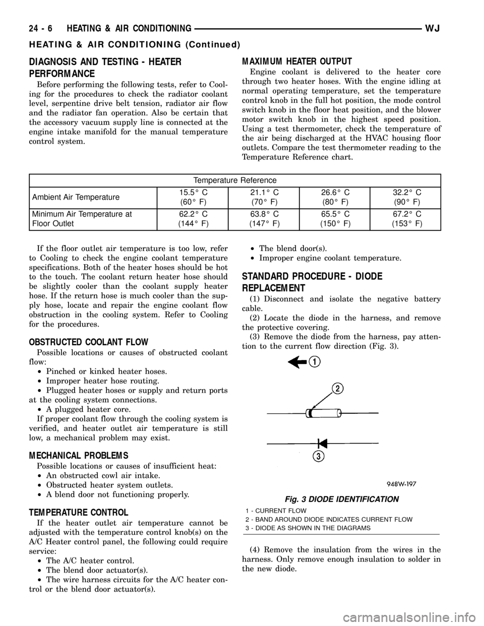
Temperature Reference chart.
Temperature Reference
Ambient Air Temperature15.5É C
(60É F)21.1É C
(70É F)26.6É C
(80É F)32.2É C
(90É F)
Minimum Air Temperature at
Floor Outlet62.2É C
(144É F)63.8É C
(147É F)65.5É C
(150É F)67.2É C
(153É F)
If the floor outlet air temperature is too low, refer
to Cooling to check the engine coolant temperature
specifications. Both of the heater hoses should be hot
to the touch. The coolant return heater hose should
be slightly cooler than the coolant supply heater
hose. If the return hose is much cooler than the sup-
ply hose, locate and repair the engine coolant flow
obstruction in the cooling system. Refer to Cooling
for the procedures.
OBSTRUCTED COOLANT FLOW
Possible locations or causes of obstructed coolant
flow:
²Pinched or kinked heater hoses.
²Improper heater hose routing.
²Plugged heater hoses or supply and return ports
at the cooling system connections.
²A plugged heater core.
If proper coolant flow through the cooling system is
verified, and heater outlet air temperature is still
low, a mechanical problem may exist.
MECHANICAL PROBLEMS
Possible locations or causes of insufficient heat:
²An obstructed cowl air intake.
²Obstructed heater system outlets.
²A blend door not functioning properly.
TEMPERATURE CONTROL
If the heater outlet air temperature cannot be
adjusted with the temperature control knob(s) on the
A/C Heater control panel, the following could require
service:
²The A/C heater control.
²The blend door actuator(s).
²The wire harness circuits for the A/C heater con-
trol or the blend door actuator(s).²The blend door(s).
²Improper engine coolant temperature.
STANDARD PROCEDURE - DIODE
REPLACEMENT
(1) Disconnect and isolate the negative battery
cable.
(2) Locate the diode in the harness, and remove
the protective covering.
(3) Remove the diode from the harness, pay atten-
tion to the current flow direction (Fig. 3).
(4) Remove the insulation from the wires in the
harness. Only remove enough insulation to solder in
the new diode.
Fig. 3 DIODE IDENTIFICATION
1 - CURRENT FLOW
2 - BAND AROUND DIODE INDICATES CURRENT FLOW
3 - DIODE AS SHOWN IN THE DIAGRAMS
24 - 6 HEATING & AIR CONDITIONINGWJ
HEATING & AIR CONDITIONING (Continued)
Page 2084 of 2199
(5) Install the new diode in the harness, making
sure current flow is correct. If necessary refer to the
appropriate wiring diagram for current flow.
(6) Solder the connection together using rosin core
type solder only.Do not use acid core solder.
(7) Tape the diode to the harness using electrical
tape making, sure the diode is completely sealed
from the elements.
(8) Re-connect the battery, and test affected sys-
tems.SPECIFICATIONS
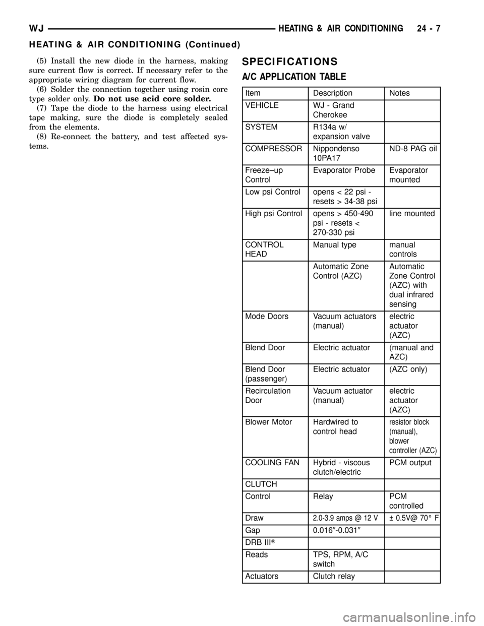
A/C APPLICATION TABLE
Item Description Notes
VEHICLE WJ - Grand
Cherokee
SYSTEM R134a w/
expansion valve
COMPRESSOR Nippondenso
10PA17ND-8 PAG oil
Freeze±up
ControlEvaporator Probe Evaporator
mounted
Low psi Control opens < 22 psi -
resets > 34-38 psi
High psi Control opens > 450-490
psi - resets <
270-330 psiline mounted
CONTROL
HEADManual type manual
controls
Automatic Zone
Control (AZC)Automatic
Zone Control
(AZC) with
dual infrared
sensing
Mode Doors Vacuum actuators
(manual)electric
actuator
(AZC)
Blend Door Electric actuator (manual and
AZC)
Blend Door
(passenger)Electric actuator (AZC only)
Recirculation
DoorVacuum actuator
(manual)electric
actuator
(AZC)
Blower Motor Hardwired to
control head
resistor block
(manual),
blower
controller (AZC)
COOLING FAN Hybrid - viscous
clutch/electricPCM output
CLUTCH
Control Relay PCM
controlled
Draw
2.0-3.9 amps @ 12 V 0.5V@ 70É F
Gap 0.0169-0.0319
DRB IIIT
Reads TPS, RPM, A/C
switch
Actuators Clutch relay
WJHEATING & AIR CONDITIONING 24 - 7
HEATING & AIR CONDITIONING (Continued)
Page 2085 of 2199
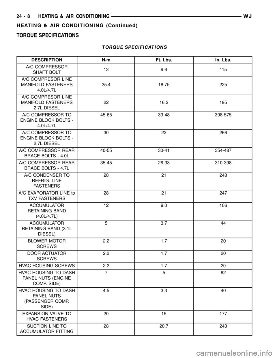
TORQUE SPECIFICATIONS
TORQUE SPECIFICATIONS
DESCRIPTION N´m Ft. Lbs. In. Lbs.
A/C COMPRESSOR
SHAFT BOLT13 9.6 115
A/C COMPRESOR LINE
MANIFOLD FASTENERS
4.0L/4.7L25.4 18.75 225
A/C COMPRESOR LINE
MANIFOLD FASTENERS
2.7L DIESEL22 16.2 195
A/C COMPRESSOR TO
ENGINE BLOCK BOLTS -
4.0L/4.7L45-65 33-48 398-575
A/C COMPRESSOR TO
ENGINE BLOCK BOLTS -
2.7L DIESEL30 22 266
A/C COMPRESSOR REAR
BRACE BOLTS - 4.0L40-55 30-41 354-487
A/C COMPRESSOR REAR
BRACE BOLTS - 4.7L35-45 26-33 310-398
A/C CONDENSER TO
REFRIG. LINE
FASTENERS28 21 248
A/C EVAPORATOR LINE to
TXV FASTENERS28 21 247
ACCUMULATOR
RETAINING BAND
(4.0L/4.7L)12 9.0 106
ACCUMULATOR
RETAINING BAND (3.1L
DIESEL)5 3.7 44
BLOWER MOTOR
SCREWS2.2 1.7 20
DOOR ACTUATOR
SCREWS2.2 1.7 20
HVAC HOUSING SCREWS 2.2 1.7 20
HVAC HOUSING TO DASH
PANEL NUTS (ENGINE
COMP. SIDE)75 62
HVAC HOUSING TO DASH
PANEL NUTS
(PASSENGER COMP.
SIDE)4.5 3.3 40
EXPANSION VALVE TO
HVAC FASTENERS20 15 177
SUCTION LINE TO
ACCUMULATOR FITTING28 20.7 248
24 - 8 HEATING & AIR CONDITIONINGWJ
HEATING & AIR CONDITIONING (Continued)
Page 2128 of 2199

PLUMBING
TABLE OF CONTENTS
page page
PLUMBING
DESCRIPTION - REFRIGERANT LINE.......52
OPERATION - REFRIGERANT LINE.........52
WARNING.............................52
CAUTION
CAUTION...........................53
REFRIGERANT HOSES/LINES/TUBES
PRECAUTIONS.......................53
DIAGNOSIS AND TESTING - REFRIGERANT
SYSTEM LEAKS......................54
STANDARD PROCEDURE
STANDARD PROCEDURE - REFRIGERANT
SYSTEM SERVICE EQUIPMENT..........54
STANDARD PROCEDURE - REFRIGERANT
RECOVERY..........................55
STANDARD PROCEDURE - REFRIGERANT
SYSTEM EVACUATE...................55
STANDARD PROCEDURE - REFRIGERANT
SYSTEM CHARGE.....................56
SPECIFICATIONS
CHARGE CAPACITY...................57
A/C COMPRESSOR
DESCRIPTION
DESCRIPTION - A/C COMPRESSOR.......57
DESCRIPTION - HIGH PRESSURE RELIEF
VALVE..............................57
OPERATION
OPERATION - A/C COMPRESSOR........57
OPERATION - HIGH PRESSURE RELIEF
VALVE..............................57
DIAGNOSIS AND TESTING - COMPRESSOR
NOISE..............................58
REMOVAL
REMOVAL...........................58
REMOVAL - 2.7L TURBO DIESEL.........60
INSTALLATION
INSTALLATION.......................61
INSTALLATION - 2.7L TURBO DIESEL......61
A/C CONDENSER
DESCRIPTION.........................62
OPERATION...........................62
REMOVAL.............................62
INSTALLATION.........................63
A/C DISCHARGE LINE
REMOVAL
REMOVAL - 2.7L TURBO DIESEL.........63
REMOVAL...........................64INSTALLATION
INSTALLATION - 2.7L TURBO DIESEL......64
INSTALLATION.......................65
A/C EXPANSION VALVE
DESCRIPTION.........................65
OPERATION...........................65
DIAGNOSIS AND TESTING - A/C EXPANSION
VALVE ..............................65
REMOVAL.............................66
INSTALLATION.........................66
LIQUID LINE
REMOVAL
REMOVAL...........................66
REMOVAL - 2.7L TURBO DIESEL.........66
INSTALLATION
INSTALLATION.......................66
INSTALLATION - 2.7L TURBO DIESEL......67
SUCTION LINE
REMOVAL
REMOVAL...........................67
REMOVAL - 2.7L TURBO DIESEL.........68
INSTALLATION
INSTALLATION.......................68
INSTALLATION - 2.7L TURBO DIESEL......69
A/C EVAPORATOR
DESCRIPTION.........................69
OPERATION...........................69
REMOVAL.............................69
INSTALLATION.........................70
HEATER CORE
DESCRIPTION.........................71
OPERATION...........................71
REMOVAL.............................71
INSTALLATION.........................71
RECEIVER / DRIER
DESCRIPTION.........................72
OPERATION...........................72
REMOVAL.............................73
INSTALLATION.........................73
REFRIGERANT
DESCRIPTION.........................75
OPERATION...........................75
REFRIGERANT OIL
DESCRIPTION.........................75
OPERATION...........................75
STANDARD PROCEDURE - REFRIGERANT
OIL LEVEL...........................75
WJPLUMBING 24 - 51
Page 2134 of 2199
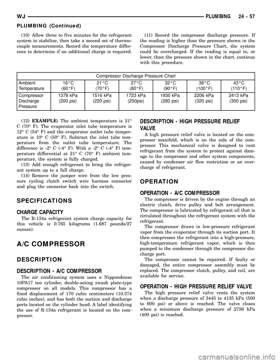
(10) Allow three to five minutes for the refrigerant
system to stabilize, then take a second set of thermo-
couple measurements. Record the temperature differ-
ence to determine if an additional charge is required.(11) Record the compressor discharge pressure. If
the reading is higher than the pressure shown in the
Compressor Discharge Pressure Chart, the system
could be overcharged. If the reading is equal to, or
lower, than the pressure shown in the chart, continue
with this procedure.
Compressor Discharge Pressure Chart
Ambient
Temperature16ÉC
(60ÉF)21ÉC
(70ÉF)27ÉC
(80ÉF)32ÉC
(90ÉF)38ÉC
(100ÉF)43ÉC
(110ÉF)
Compressor
Discharge
Pressure1378 kPa
(200 psi)1516 kPa
(220 psi)1723 kPa
(250psi)1930 kPa
(280 psi)2206 kPa
(320 psi)2413 kPa
(350 psi)
(12)EXAMPLE:The ambient temperature is 21É
C (70É F). The evaporator inlet tube temperature is
12É C (54É F) and the evaporator outlet tube temper-
ature is 10É C (50É F). Subtract the inlet tube tem-
perature from the outlet tube temperature. The
difference is -2É C (-4É F). With a -2É C (-4É F) tem-
perature differential at 21É C (70É F) ambient tem-
perature, the system is fully charged.
(13) Add enough refrigerant to bring the refriger-
ant system up to a full charge.
(14) Remove the jumper wire from the low pres-
sure cycling clutch switch wire harness connector
and plug the connector back into the switch.
SPECIFICATIONS
CHARGE CAPACITY
The R-134a refrigerant system charge capacity for
this vehicle is 0.765 kilograms (1.687 pounds/27
ounces).
A/C COMPRESSOR
DESCRIPTION
DESCRIPTION - A/C COMPRESSOR
The air conditioning system uses a Nippondenso
10PA17 ten cylinder, double-acting swash plate-type
compressor on all models. This compressor has a
fixed displacement of 170 cubic centimeters (10.374
cubic inches), and has both the suction and discharge
ports located on the cylinder head. A label identifying
the use of R-134a refrigerant is located on the com-
pressor.
DESCRIPTION - HIGH PRESSURE RELIEF
VALVE
A high pressure relief valve is located on the com-
pressor manifold, which is on the side of the com-
pressor. This mechanical valve is designed to vent
refrigerant from the system to protect against dam-
age to the compressor and other system components,
caused by condenser air flow restriction or an over-
charge of refrigerant.
OPERATION
OPERATION - A/C COMPRESSOR
The compressor is driven by the engine through an
electric clutch, drive pulley and belt arrangement.
The compressor is lubricated by refrigerant oil that is
circulated throughout the refrigerant system with the
refrigerant.
The compressor draws in low-pressure refrigerant
vapor from the evaporator through its suction port. It
then compresses the refrigerant into a high-pressure,
high-temperature refrigerant vapor, which is then
pumped to the condenser through the compressor dis-
charge port.
The compressor cannot be repaired. If faulty or
damaged, the entire compressor assembly must be
replaced. The compressor clutch, pulley, and coil, are
available for service.
OPERATION - HIGH PRESSURE RELIEF VALVE
The high pressure relief valve vents the system
when a discharge pressure of 3445 to 4135 kPa (500
to 600 psi) or above is reached. The valve closes
when a minimum discharge pressure of 2756 kPa
(400 psi) is reached.
WJPLUMBING 24 - 57
PLUMBING (Continued)
Page 2135 of 2199

The high pressure relief valve vents only enough
refrigerant to reduce the system pressure, and then
re-seats itself. The majority of the refrigerant is con-
served in the system. If the valve vents refrigerant, it
does not mean that the valve is faulty.
The high pressure relief valve is a factory-cali-
brated unit. The valve cannot be adjusted or
repaired, and must not be removed or otherwise dis-
turbed. The valve is only serviced as a part of the
compressor assembly.
DIAGNOSIS AND TESTING - COMPRESSOR
NOISE
When investigating an air conditioning related
noise, you must first know the conditions under
which the noise occurs. These conditions include:
weather, vehicle speed, transmission in gear or neu-
tral, engine speed, engine temperature, and any
other special conditions. Noises that develop during
air conditioning operation can often be misleading.
For example: What sounds like a failed front bearing
or connecting rod, may be caused by loose bolts, nuts,
mounting brackets, or a loose compressor clutch
assembly.
Drive belts are speed sensitive. At different engine
speeds and depending upon belt tension, belts can
develop noises that are mistaken for a compressor
noise. Improper belt tension can cause a misleading
noise when the compressor clutch is engaged, which
may not occur when the compressor clutch is disen-
gaged. Check the serpentine drive belt condition and
tension as described in Cooling before beginning this
procedure.
(1) Select a quiet area for testing. Duplicate the
complaint conditions as much as possible. Switch the
compressor on and off several times to clearly iden-
tify the compressor noise. Listen to the compressor
while the clutch is engaged and disengaged. Probe
the compressor with an engine stethoscope or a long
screwdriver with the handle held to your ear to bet-
ter localize the source of the noise.
(2) Loosen all of the compressor mounting hard-
ware and retighten. Tighten the compressor clutch
mounting nut. Be certain that the clutch coil is
mounted securely to the compressor, and that the
clutch plate and pulley are properly aligned and have
the correct air gap. (Refer to 24 - HEATING & AIR
CONDITIONING/CONTROLS/A/C COMPRESSOR
CLUTCH - INSTALLATION)
(3) To duplicate a high-ambient temperature condi-
tion (high head pressure), restrict the air flow
through the condenser. Install a manifold gauge set
to be certain that the discharge pressure does not
exceed 2760 kPa (400 psi).
(4) Check the refrigerant system plumbing for
incorrect routing, rubbing or interference, which cancause unusual noises. Also check the refrigerant lines
for kinks or sharp bends that will restrict refrigerant
flow, which can cause noises. (Refer to 24 - HEAT-
ING & AIR CONDITIONING/PLUMBING - CAU-
TION - REFRIGERANT HOSES/LINES/TUBES
PRECAUTIONS)
(5) If the noise is from opening and closing of the
high pressure relief valve, reclaim, evacuate, and
recharge the refrigerant system. (Refer to 24 - HEAT-
ING & AIR CONDITIONING/PLUMBING - STAN-
DARD PROCEDURE - REFRIGERANT RECOVERY)
(Refer to 24 - HEATING & AIR CONDITIONING/
PLUMBING - STANDARD PROCEDURE - REFRIG-
ERANT SYSTEM EVACUATE) (Refer to 24 -
HEATING & AIR CONDITIONING/PLUMBING -
STANDARD PROCEDURE - REFRIGERANT SYS-
TEM CHARGE)If the high pressure relief valve still
does not seat properly, replace the a/c compressor.
(Refer to 24 - HEATING & AIR CONDITIONING/
PLUMBING/A/C COMPRESSOR - REMOVAL)
(6) If the noise is from liquid slugging on the suc-
tion line, check the refrigerant oil level and the
refrigerant system charge. (Refer to 24 - HEATING
& AIR CONDITIONING/PLUMBING/REFRIGER-
ANT OIL - STANDARD PROCEDURE) (Refer to 24 -
HEATING & AIR CONDITIONING/PLUMBING -
SPECIFICATIONS - CHARGE CAPACITY).
(7) If the noise continues, replace the compressor
and repeat Step 1.
REMOVAL
REMOVAL
The compressor may be removed and repositioned
without disconnecting the refrigerant lines or dis-
charging the refrigerant system. Discharging is not
necessary if servicing the compressor clutch or clutch
coil, the engine, the cylinder head, or the generator.
WARNING: REVIEW THE WARNINGS AND CAU-
TIONS IN THE FRONT OF THIS SECTION BEFORE
PERFORMING THE FOLLOWING OPERATION.
(Refer to 24 - HEATING & AIR CONDITIONING/
PLUMBING - WARNING) (Refer to 24 - HEATING &
AIR CONDITIONING/PLUMBING - CAUTION)
(1) Recover the refrigerant from the system. (Refer
to 24 - HEATING & AIR CONDITIONING/PLUMB-
ING - STANDARD PROCEDURE - REFRIGERANT
RECOVERY)
(2) Disconnect and isolate the battery negative
cable.
(3) Remove the serpentine drive belt. Refer to
Cooling for the procedures.
(4) Unplug the compressor clutch coil wire harness
connector.
24 - 58 PLUMBINGWJ
A/C COMPRESSOR (Continued)
Page 2173 of 2199

tive system and seal the evaporative system so the
leak detection test can be run.
The primary components within the assembly are:
A three port solenoid that activates both of the func-
tions listed above; a pump which contains a switch,
two check valves and a spring/diaphragm, a canister
vent valve (CVV) seal which contains a spring loaded
vent seal valve.
Immediately after a cold start, between predeter-
mined temperature thresholds limits, the three port
solenoid is briefly energized. This initializes the
pump by drawing air into the pump cavity and also
closes the vent seal. During non test conditions the
vent seal is held open by the pump diaphragm
assembly which pushes it open at the full travel posi-
tion. The vent seal will remain closed while the
pump is cycling due to the reed switch triggering of
the three port solenoid that prevents the diaphragm
assembly from reaching full travel. After the brief
initialization period, the solenoid is de-energized
allowing atmospheric pressure to enter the pump
cavity, thus permitting the spring to drive the dia-
phragm which forces air out of the pump cavity and
into the vent system. When the solenoid is energized
and de energized, the cycle is repeated creating flow
in typical diaphragm pump fashion. The pump is con-
trolled in 2 modes:
Pump Mode:The pump is cycled at a fixed rate to
achieve a rapid pressure build in order to shorten the
overall test length.
Test Mode:The solenoid is energized with a fixed
duration pulse. Subsequent fixed pulses occur when
the diaphragm reaches the Switch closure point.
The spring in the pump is set so that the system
will achieve an equalized pressure of about 7.5º
water. The cycle rate of pump strokes is quite rapid
as the system begins to pump up to this pressure. As
the pressure increases, the cycle rate starts to drop
off. If there is no leak in the system, the pump would
eventually stop pumping at the equalized pressure. If
there is a leak, it will continue to pump at a rate rep-
resentative of the flow characteristic of the size of the
leak. From this information we can determine if the
leak is larger than the required detection limit (cur-
rently set at .040º orifice by CARB). If a leak is
revealed during the leak test portion of the test, the
test is terminated at the end of the test mode and no
further system checks will be performed.
After passing the leak detection phase of the test,
system pressure is maintained by turning on the
LDP's solenoid until the purge system is activated.
Purge activation in effect creates a leak. The cycle
rate is again interrogated and when it increases due
to the flow through the purge system, the leak check
portion of the diagnostic is complete.The canister vent valve will unseal the system
after completion of the test sequence as the pump
diaphragm assembly moves to the full travel position.
Evaporative system functionality will be verified by
using the stricter evap purge flow monitor. At an
appropriate warm idle the LDP will be energized to
seal the canister vent. The purge flow will be clocked
up from some small value in an attempt to see a
shift in the 02 control system. If fuel vapor, indicated
by a shift in the 02 control, is present the test is
passed. If not, it is assumed that the purge system is
not functioning in some respect. The LDP is again
turned off and the test is ended.
MISFIRE MONITOR
Excessive engine misfire results in increased cata-
lyst temperature and causes an increase in HC emis-
sions. Severe misfires could cause catalyst damage.
To prevent catalytic convertor damage, the PCM
monitors engine misfire.
The Powertrain Control Module (PCM) monitors
for misfire during most engine operating conditions
(positive torque) by looking at changes in the crank-
shaft speed. If a misfire occurs the speed of the
crankshaft will vary more than normal.
FUEL SYSTEM MONITOR
To comply with clean air regulations, vehicles are
equipped with catalytic converters. These converters
reduce the emission of hydrocarbons, oxides of nitro-
gen and carbon monoxide. The catalyst works best
when the Air Fuel (A/F) ratio is at or near the opti-
mum of 14.7 to 1.
The PCM is programmed to maintain the optimum
air/fuel ratio of 14.7 to 1. This is done by making
short term corrections in the fuel injector pulse width
based on the O2S sensor output. The programmed
memory acts as a self calibration tool that the engine
controller uses to compensate for variations in engine
specifications, sensor tolerances and engine fatigue
over the life span of the engine. By monitoring the
actual fuel-air ratio with the O2S sensor (short term)
and multiplying that with the program long-term
(adaptive) memory and comparing that to the limit,
it can be determined whether it will pass an emis-
sions test. If a malfunction occurs such that the PCM
cannot maintain the optimum A/F ratio, then the
MIL will be illuminated.
CATALYST MONITOR
To comply with clean air regulations, vehicles are
equipped with catalytic converters. These converters
reduce the emission of hydrocarbons, oxides of nitro-
gen and carbon monoxide.
Normal vehicle miles or engine misfire can cause a
catalyst to decay. This can increase vehicle emissions
25 - 18 EMISSIONS CONTROLWJ
EMISSIONS CONTROL (Continued)