Specifications JEEP GRAND CHEROKEE 2002 WJ / 2.G Workshop Manual
[x] Cancel search | Manufacturer: JEEP, Model Year: 2002, Model line: GRAND CHEROKEE, Model: JEEP GRAND CHEROKEE 2002 WJ / 2.GPages: 2199, PDF Size: 76.01 MB
Page 1574 of 2199
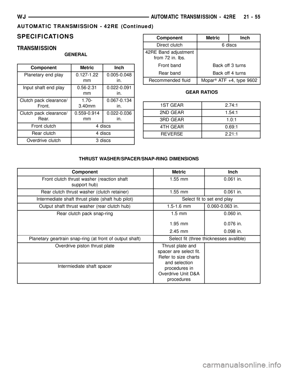
SPECIFICATIONS
TRANSMISSION
GENERAL
Component Metric Inch
Planetary end play 0.127-1.22
mm0.005-0.048
in.
Input shaft end play 0.56-2.31
mm0.022-0.091
in.
Clutch pack clearance/
Front.1.70-
3.40mm0.067-0.134
in.
Clutch pack clearance/
Rear.0.559-0.914
mm0.022-0.036
in.
Front clutch 4 discs
Rear clutch 4 discs
Overdrive clutch 3 discs
Component Metric Inch
Direct clutch 6 discs
42RE Band adjustment
from 72 in. lbs.
Front band Back off 3 turns
Rear band Back off 4 turns
Recommended fluid MoparTATF +4, type 9602
GEAR RATIOS
1ST GEAR 2.74:1
2ND GEAR 1.54:1
3RD GEAR 1.0:1
4TH GEAR 0.69:1
REVERSE 2.21:1
THRUST WASHER/SPACER/SNAP-RING DIMENSIONS
Component Metric Inch
Front clutch thrust washer (reaction shaft
support hub)1.55 mm 0.061 in.
Rear clutch thrust washer (clutch retainer) 1.55 mm 0.061 in.
Intermediate shaft thrust plate (shaft hub pilot) Select fit to set end play
Output shaft thrust washer (rear clutch hub) 1.5-1.6 mm 0.060-0.063 in.
Rear clutch pack snap-ring 1.5 mm 0.060 in.
1.95 mm 0.076 in.
2.45 mm 0.098 in.
Planetary geartrain snap-ring (at front of output shaft) Select fit (three thicknesses avalible)
Overdrive piston thrust plate Thrust plate and
spacer are select fit.
Refer to size charts
and selection
procedures in
Overdrive Unit D&A
procedures Intermiediate shaft spacer
WJAUTOMATIC TRANSMISSION - 42RE 21 - 55
AUTOMATIC TRANSMISSION - 42RE (Continued)
Page 1575 of 2199
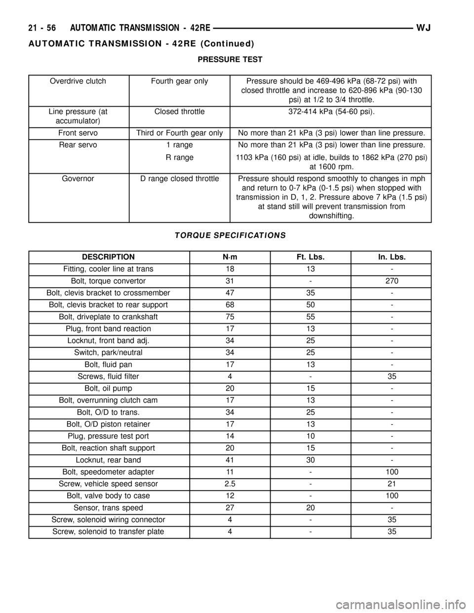
PRESSURE TEST
Overdrive clutch Fourth gear only Pressure should be 469-496 kPa (68-72 psi) with
closed throttle and increase to 620-896 kPa (90-130
psi) at 1/2 to 3/4 throttle.
Line pressure (at
accumulator)Closed throttle 372-414 kPa (54-60 psi).
Front servo Third or Fourth gear only No more than 21 kPa (3 psi) lower than line pressure.
Rear servo 1 range No more than 21 kPa (3 psi) lower than line pressure.
R range 1103 kPa (160 psi) at idle, builds to 1862 kPa (270 psi)
at 1600 rpm.
Governor D range closed throttle Pressure should respond smoothly to changes in mph
and return to 0-7 kPa (0-1.5 psi) when stopped with
transmission in D, 1, 2. Pressure above 7 kPa (1.5 psi)
at stand still will prevent transmission from
downshifting.
TORQUE SPECIFICATIONS
DESCRIPTION N´m Ft. Lbs. In. Lbs.
Fitting, cooler line at trans 18 13 -
Bolt, torque convertor 31 - 270
Bolt, clevis bracket to crossmember 47 35 -
Bolt, clevis bracket to rear support 68 50 -
Bolt, driveplate to crankshaft 75 55 -
Plug, front band reaction 17 13 -
Locknut, front band adj. 34 25 -
Switch, park/neutral 34 25 -
Bolt, fluid pan 17 13 -
Screws, fluid filter 4 - 35
Bolt, oil pump 20 15 -
Bolt, overrunning clutch cam 17 13 -
Bolt, O/D to trans. 34 25 -
Bolt, O/D piston retainer 17 13 -
Plug, pressure test port 14 10 -
Bolt, reaction shaft support 20 15 -
Locknut, rear band 41 30 -
Bolt, speedometer adapter 11 - 100
Screw, vehicle speed sensor 2.5 - 21
Bolt, valve body to case 12 - 100
Sensor, trans speed 27 20 -
Screw, solenoid wiring connector 4 - 35
Screw, solenoid to transfer plate 4 - 35
21 - 56 AUTOMATIC TRANSMISSION - 42REWJ
AUTOMATIC TRANSMISSION - 42RE (Continued)
Page 1696 of 2199

AUTOMATIC TRANSMISSION - 545RFE
TABLE OF CONTENTS
page page
AUTOMATIC TRANSMISSION - 545RFE
DESCRIPTION........................178
OPERATION..........................179
DIAGNOSIS AND TESTING
DIAGNOSIS AND TESTING - AUTOMATIC
TRANSMISSION.....................179
DIAGNOSIS AND TESTING - PRELIMINARY . 180
DIAGNOSIS AND TESTING - ROAD
TESTING...........................180
DIAGNOSIS AND TESTING - HYDRAULIC
PRESSURE TEST....................181
DIAGNOSIS AND TESTING - AIR CHECKING
TRANSMISSION CLUTCH OPERATION....182
DIAGNOSIS AND TESTING - CONVERTER
HOUSING FLUID LEAK................182
STANDARD PROCEDURE - ALUMINUM
THREAD REPAIR.....................183
REMOVAL............................183
DISASSEMBLY........................185
CLEANING...........................190
INSPECTION.........................190
ASSEMBLY...........................190
INSTALLATION........................197
SCHEMATICS AND DIAGRAMS
HYDRAULIC SCHEMATICS.............199
SPECIFICATIONS
TRANSMISSION.....................220
SPECIAL TOOLS
RFE TRANSMISSION.................221
4C RETAINER/BULKHEAD
DISASSEMBLY........................224
ASSEMBLY...........................224
ADAPTER HOUSING SEAL
REMOVAL............................225
INSTALLATION........................225
BRAKE TRANSMISSION SHIFT INTERLOCK
MECHANISM
DESCRIPTION........................226
OPERATION..........................226
DIAGNOSIS AND TESTING - BRAKE
TRANSMISSION SHIFT INTERLOCK......226
ADJUSTMENTS - BRAKE TRANSMISSION
SHIFT INTERLOCK...................227
FLUID AND FILTER
DIAGNOSIS AND TESTING
DIAGNOSIS AND TESTING - EFFECTS OF
INCORRECT FLUID LEVEL.............228
DIAGNOSIS AND TESTING - CAUSES OF
BURNT FLUID.......................228DIAGNOSIS AND TESTING - FLUID
CONTAMINATION....................228
STANDARD PROCEDURE
STANDARD PROCEDURE - FLUID LEVEL
CHECK............................229
STANDARD PROCEDURE - FLUID AND
FILTER REPLACEMENT...............230
STANDARD PROCEDURE - TRANSMISSION
FILL...............................230
GEARSHIFT CABLE
DIAGNOSIS AND TESTING - GEARSHIFT
CABLE.............................231
REMOVAL............................231
INSTALLATION........................231
ADJUSTMENTS - GEARSHIFT CABLE......232
HOLDING CLUTCHES
DESCRIPTION........................233
OPERATION..........................234
INPUT CLUTCH ASSEMBLY
DESCRIPTION........................235
OPERATION..........................235
DISASSEMBLY........................237
ASSEMBLY...........................238
INPUT SPEED SENSOR
DESCRIPTION........................244
OPERATION..........................244
REMOVAL............................244
INSTALLATION........................244
LINE PRESSURE (LP) SENSOR
DESCRIPTION........................245
OPERATION..........................245
REMOVAL............................245
INSTALLATION........................245
LOW/REVERSE CLUTCH
DISASSEMBLY........................246
CLEANING...........................247
INSPECTION.........................247
ASSEMBLY...........................247
OIL PUMP
DESCRIPTION........................248
OPERATION..........................248
STANDARD PROCEDURE - OIL PUMP
VOLUME CHECK.....................249
DISASSEMBLY........................250
CLEANING...........................252
INSPECTION.........................252
ASSEMBLY...........................253
OIL PUMP FRONT SEAL
REMOVAL............................253
WJAUTOMATIC TRANSMISSION - 545RFE 21 - 177
Page 1739 of 2199
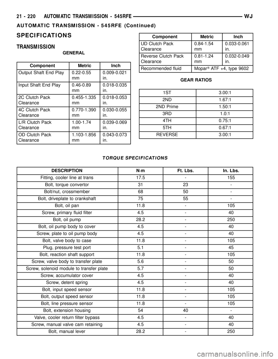
SPECIFICATIONS
TRANSMISSION
GENERAL
Component Metric Inch
Output Shaft End Play 0.22-0.55
mm0.009-0.021
in.
Input Shaft End Play 0.46-0.89
mm0.018-0.035
in.
2C Clutch Pack
Clearance0.455-1.335
mm0.018-0.053
in.
4C Clutch Pack
Clearance0.770-1.390
mm0.030-0.055
in.
L/R Clutch Pack
Clearance1.00-1.74
mm0.039-0.069
in.
OD Clutch Pack
Clearance1.103-1.856
mm0.043-0.073
in.
Component Metric Inch
UD Clutch Pack
Clearance0.84-1.54
mm0.033-0.061
in.
Reverse Clutch Pack
Clearance0.81-1.24
mm0.032-0.049
in.
Recommended fluid MoparTATF +4, type 9602
GEAR RATIOS
1ST 3.00:1
2ND 1.67:1
2ND Prime 1.50:1
3RD 1.0:1
4TH 0.75:1
5TH 0.67:1
REVERSE 3.00:1
TORQUE SPECIFICATIONS
DESCRIPTION N´m Ft. Lbs. In. Lbs.
Fitting, cooler line at trans 17.5 - 155
Bolt, torque convertor 31 23 -
Bolt/nut, crossmember 68 50 -
Bolt, driveplate to crankshaft 75 55 -
Bolt, oil pan 11.8 - 105
Screw, primary fluid filter 4.5 - 40
Bolt, oil pump 28.2 - 250
Bolt, oil pump body to cover 4.5 - 40
Screw, plate to oil pump body 4.5 - 40
Bolt, valve body to case 11.8 - 105
Plug, pressure test port 5.1 - 45
Bolt, reaction shaft support 11.8 - 105
Screw, valve body to transfer plate 5.6 - 50
Screw, solenoid module to transfer plate 5.7 - 50
Screw, accumulator cover 4.5 - 40
Screw, detent spring 4.5 - 40
Bolt, input speed sensor 11.8 - 105
Bolt, output speed sensor 11.8 - 105
Bolt, line pressure sensor 11.8 - 105
Bolt, extension housing 54 40 -
Valve, cooler return filter bypass 4.5 - 40
Screw, manual valve cam retaining 4.5 - 40
Bolt, manual lever 28.2 - 250
21 - 220 AUTOMATIC TRANSMISSION - 545RFEWJ
AUTOMATIC TRANSMISSION - 545RFE (Continued)
Page 1799 of 2199

TRANSFER CASE - NV242
TABLE OF CONTENTS
page page
TRANSFER CASE - NV242
DESCRIPTION........................280
OPERATION..........................281
DIAGNOSIS AND TESTING - TRANSFER
CASE - NV242.......................281
REMOVAL............................282
DISASSEMBLY........................282
CLEANING...........................292
INSPECTION.........................293
ASSEMBLY...........................295
INSTALLATION........................307
SPECIFICATIONS
TRANSFER CASE - NV242.............308
SPECIAL TOOLS
TRANSFER CASE - NV242.............308
FLUID
STANDARD PROCEDURE - FLUID DRAIN/
REFILL............................310FRONT OUTPUT SHAFT SEAL
REMOVAL............................310
INSTALLATION........................310
POSITION SENSOR
DESCRIPTION........................311
OPERATION..........................311
REMOVAL............................312
INSTALLATION........................312
REAR RETAINER BUSHING AND SEAL -
NV242HD
REMOVAL............................312
INSTALLATION........................312
SHIFT CABLE
REMOVAL............................313
INSTALLATION........................313
TRANSFER CASE - NV242
DESCRIPTION
The NV242 is a full transfer case (Fig. 1). It pro-
vides full time 2-wheel, or 4-wheel drive operation.
A differential in the transfer case is used to control
torque transfer to the front and rear axles. A low
range gear provides increased low speed torque capa-
bility for off road operation. The low range provides a
2.72:1 reduction ratio.
The geartrain is mounted in two aluminum case
halves attached with bolts. The mainshaft front and
rear bearings are mounted in aluminum retainer
housings bolted to the case halves.
TRANSFER CASE IDENTIFICATION
Two versions of the NV242 are used in the WJ
vehicles, NV242LD and NV242HD. The two transfer
cases can be distinguished from one another by the
rear output shaft retainer. The NV242LD uses a rub-
ber boot to cover the rear output shaft, while the
NV242HD uses a cast aluminum housing. Other than
this difference, the two transfer cases are serviced
the same.
A circular ID tag is attached to the rear case of
each transfer case (Fig. 2). The ID tag provides the
transfer case model number, assembly number, serial
number, and low range ratio.The transfer case serial number also represents
the date of build.
SHIFT MECHANISM
Operating ranges are selected with a lever in the
floor mounted shifter assembly. The shift lever is con-
nected to the transfer case range lever by an adjust-
able cable. A straight line shift pattern is used.
Range positions are marked on the shifter bezel.
Fig. 1 NV242 Transfer Case
21 - 280 TRANSFER CASE - NV242WJ
Page 1827 of 2199
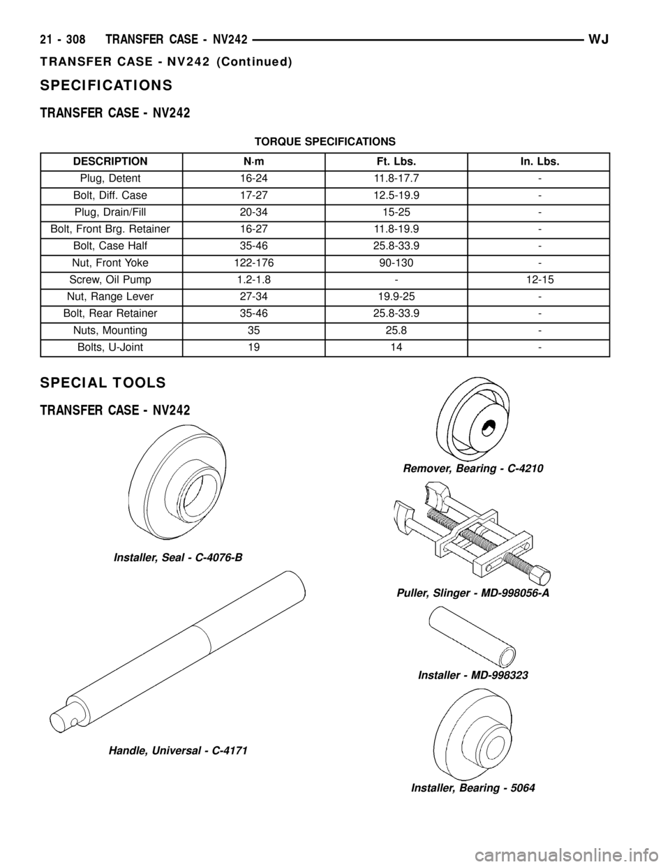
SPECIFICATIONS
TRANSFER CASE - NV242
TORQUE SPECIFICATIONS
DESCRIPTION N´m Ft. Lbs. In. Lbs.
Plug, Detent 16-24 11.8-17.7 -
Bolt, Diff. Case 17-27 12.5-19.9 -
Plug, Drain/Fill 20-34 15-25 -
Bolt, Front Brg. Retainer 16-27 11.8-19.9 -
Bolt, Case Half 35-46 25.8-33.9 -
Nut, Front Yoke 122-176 90-130 -
Screw, Oil Pump 1.2-1.8 - 12-15
Nut, Range Lever 27-34 19.9-25 -
Bolt, Rear Retainer 35-46 25.8-33.9 -
Nuts, Mounting 35 25.8 -
Bolts, U-Joint 19 14 -
SPECIAL TOOLS
TRANSFER CASE - NV242
Installer, Seal - C-4076-B
Handle, Universal - C-4171
Remover, Bearing - C-4210
Puller, Slinger - MD-998056-A
Installer - MD-998323
Installer, Bearing - 5064
21 - 308 TRANSFER CASE - NV242WJ
TRANSFER CASE - NV242 (Continued)
Page 1834 of 2199

TRANSFER CASE - NV247
TABLE OF CONTENTS
page page
TRANSFER CASE - NV247
DESCRIPTION........................315
OPERATION..........................316
DIAGNOSIS AND TESTING - TRANSFER
CASE - NV247.......................316
REMOVAL............................317
DISASSEMBLY........................317
CLEANING...........................324
INSPECTION.........................324
ASSEMBLY...........................326
INSTALLATION........................335
SPECIFICATIONS
TRANSFER CASE - NV247.............336
SPECIAL TOOLS
TRANSFER CASE - NV247.............337FLUID
STANDARD PROCEDURE - FLUID DRAIN/
REFILL............................338
FRONT OUTPUT SHAFT SEAL
REMOVAL............................338
INSTALLATION........................338
REAR RETAINER BUSHING AND SEAL
REMOVAL............................339
INSTALLATION........................339
SHIFT CABLE
REMOVAL............................340
INSTALLATION........................340
TRANSFER CASE - NV247
DESCRIPTION
The NV247 (Fig. 1) is an on-demand 4-wheel drive
transfer case with two operating ranges and a neu-
tral position. Operating ranges are 4-high and 4-low.
The 4-low range is used for extra pulling power in
off-road situations.
TRANSFER CASE IDENTIFICATION
A circular I.D. tag is attached to the rear case of
each NV247 transfer case (Fig. 2). The tag indicates
the following information:
²Model number
²Serial number
²Assembly number
²Gear ratio
²Location of manufacture
The transfer case serial number also represents
the date of build.
Fig. 1 NV247 Transfer Case
Fig. 2 Transfer Case I.D. Tag
1 - FILL PLUG
2 - I.D. TAG
3 - DRAIN PLUG
WJTRANSFER CASE - NV247 21 - 315
Page 1855 of 2199
(6) Connect front propeller shaft and install rear
propeller shaft. (Refer to 3 - DIFFERENTIAL &
DRIVELINE/PROPELLER SHAFT/PROPELLER
SHAFT - INSTALLATION)
(7) Fill transfer case with correct fluid. Check
transmission fluid level. Correct as necessary.
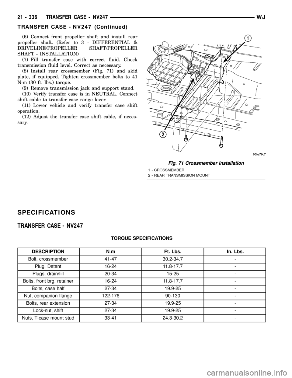
(8) Install rear crossmember (Fig. 71) and skid
plate, if equipped. Tighten crossmember bolts to 41
N´m (30 ft. lbs.) torque.
(9) Remove transmission jack and support stand.
(10) Verify transfer case is in NEUTRAL. Connect
shift cable to transfer case range lever.
(11) Lower vehicle and verify transfer case shift
operation.
(12) Adjust the transfer case shift cable, if neces-
sary.
SPECIFICATIONS
TRANSFER CASE - NV247
TORQUE SPECIFICATIONS
DESCRIPTION N´m Ft. Lbs. In. Lbs.
Bolt, crossmember 41-47 30.2-34.7 -
Plug, Detent 16-24 11.8-17.7 -
Plugs, drain/fill 20-34 15-25 -
Bolts, front brg. retainer 16-24 11.8-17.7 -
Bolts, case half 27-34 19.9-25 -
Nut, companion flange 122-176 90-130 -
Bolts, rear extension 27-34 19.9-25 -
Lock-nut, shift 27-34 19.9-25 -
Nuts, T-case mount stud 33-41 24.3-30.2 -
Fig. 71 Crossmember Installation
1 - CROSSMEMBER
2 - REAR TRANSMISSION MOUNT
21 - 336 TRANSFER CASE - NV247WJ
TRANSFER CASE - NV247 (Continued)
Page 1860 of 2199

TIRES/WHEELS
TABLE OF CONTENTS
page page
TIRES/WHEELS
DIAGNOSIS AND TESTING - TIRE AND
WHEEL RUNOUT......................1
STANDARD PROCEDURE
STANDARD PROCEDURE - TIRE AND
WHEEL BALANCE......................2
STANDARD PROCEDURE - MATCH
MOUNTING...........................4
STANDARD PROCEDURE - TIRE ROTATION . 5
STANDARD PROCEDURE - WHEEL
INSTALLATION........................5
TIRES
DESCRIPTION
DESCRIPTION - TIRES..................6
DESCRIPTION - RADIAL±PLY TIRES.......6
DESCRIPTION - TIRE INFLATION
PRESSURES..........................6
DESCRIPTION - TIRE PRESSURE FOR
HIGH SPEED..........................7
DESCRIPTION - REPLACEMENT TIRES.....7
DIAGNOSIS AND TESTING
DIAGNOSIS AND TESTING - PRESSURE
GAUGES.............................8
DIAGNOSIS AND TESTING - TREAD WEAR
INDICATORS..........................8
DIAGNOSIS AND TESTING - TIRE WEAR
PATTERNS...........................8
DIAGNOSIS AND TESTING - TIRE NOISE
OR VIBRATION........................8STANDARD PROCEDURE - REPAIRING
LEAKS...............................8
CLEANING.............................9
SPECIFICATIONS
TIRES...............................9
SPECIFICATIONS -.....................9
SPARE TIRE
DESCRIPTION - SPARE / TEMPORARY TIRE . . 10
WHEELS
DESCRIPTION.........................10
DIAGNOSIS AND TESTING - WHEEL
INSPECTION.........................10
STANDARD PROCEDURE - WHEEL
REPLACEMENT.......................10
SPECIFICATIONS
TORQUE CHART......................11
STUDS
REMOVAL.............................11
INSTALLATION.........................11
TIRE PRESSURE MONITORING
DESCRIPTION.........................12
OPERATION...........................12
DIAGNOSIS AND TESTING - TIRE PRESSURE
MONITORING SYSTEM.................12
SENSOR
REMOVAL - TIRE PRESSURE SENSOR/
TRANSMITTER.......................12
INSTALLATION - TIRE PRESSURE SENSOR/
TRANSMITTER.......................13
TIRES/WHEELS
DIAGNOSIS AND TESTING - TIRE AND WHEEL
RUNOUT
Radial runout is the difference between the high
and low points on the tire or wheel (Fig. 1).
Lateral runout is thewobbleof the tire or wheel.
Radial runout of more than 1.5 mm (.060 inch)
measured at the center line of the tread may cause
the vehicle to shake.
Lateral runout of more than 2.0 mm (.080 inch)
measured near the shoulder of the tire may cause the
vehicle to shake.
Sometimes radial runout can be reduced. Relocate
the wheel and tire assembly on the mounting studs
(See Method 1). If this does not reduce runout to an
acceptable level, the tire can be rotated on the wheel.
(See Method 2).
METHOD 1 (RELOCATE WHEEL ON HUB)
(1) Drive vehicle a short distance to eliminate tire
flat spotting from a parked position.
(2) Check wheel bearings and adjust if adjustable
or replace if necessary.
(3) Check the wheel mounting surface.
(4) Relocate wheel on the mounting, two studs
over from the original position.
(5) Tighten wheel nuts until all are properly
torqued, to eliminate brake distortion.
(6) Check radial runout. If still excessive, mark
tire sidewall, wheel, and stud at point of maximum
runout and proceed to Method 2.
METHOD 2 (RELOCATE TIRE ON WHEEL)
NOTE: Rotating the tire on wheel is particularly
effective when there is runout in both tire and
wheel.
WJTIRES/WHEELS 22 - 1
Page 1863 of 2199

STANDARD PROCEDURE - MATCH MOUNTING
Tires and wheels are currently not match mounted
at the factory. Match mounting is a technique used to
reduce runout in the wheel/tire assembly. This means
that the high spot of the tire is aligned with the low
spot on the wheel rim. The high spot on the tire is
marked with a paint mark or a bright colored adhe-
sive label on the outboard sidewall. The low spot on
the rim is identified with a label on the outside of the
rim and a dot on the inside of the rim. If the outside
label has been removed the tire will have to be
removed to locate the dot on the inside of the rim.
Before dismounting a tire from its wheel, a refer-
ence mark should be placed on the tire at the valve
stem location. This reference will ensure that it is
remounted in the original position on the wheel.
(1) Use a dial indicator to locate the high spot of
the tire on the center tread rib (Fig. 6). Record the
indicator reading and mark the high spot on the tire.
Place a mark on the tire at the valve stem location
(Fig. 7).
(2) Break down the tire and remount it 180
degrees on the rim (Fig. 8).
(3) Measure the total runout again and mark the
tire to indicate the high spot.
(4) If runout is still excessive use the following
procedures.
(a) If the high spot is within 101.6 mm (4.0 in.)
of the first spot and is still excessive, replace the
tire.
(b) If the high spot is within 101.6 mm (4.0 in.)
of the first spot on the wheel, the wheel may be out
of specifications,(Refer to 22 - TIRES/WHEELS -
DIAGNOSIS AND TESTING).
(c) If the high spot is NOT within 101.6 mm (4.0
in.) of either high spot, draw an arrow on the tread
from second high spot to first. Break down the tire
and remount it 90 degrees on rim in that direction
(Fig. 9). This procedure will normally reduce the
runout to an acceptable amount.
Fig. 6 Dial Indicator
Fig. 7 First Measurement On Tire
1 - REFERENCE MARK
2 - 1ST MEASUREMENT
HIGH SPOT MARK TIRE AND RIM
3 - WHEEL
4 - VALVE STEM
Fig. 8 Remount Tire 180 Degrees
1 - VALVE STEM
2 - REFERENCE MARK
22 - 4 TIRES/WHEELSWJ
TIRES/WHEELS (Continued)