ohm JEEP GRAND CHEROKEE 2002 WJ / 2.G Owner's Manual
[x] Cancel search | Manufacturer: JEEP, Model Year: 2002, Model line: GRAND CHEROKEE, Model: JEEP GRAND CHEROKEE 2002 WJ / 2.GPages: 2199, PDF Size: 76.01 MB
Page 456 of 2199

BRAKE LAMP SWITCH
DESCRIPTION
The brake lamp switch is mounted on a bracket
attached to the brake pedal support. The switch is
adjustable.
OPERATION
The brake lamp switch is used for the brake lamp,
speed control and brake sensor circuits.
DIAGNOSIS AND TESTING Ð BRAKE LAMP
SWITCH
Brake lamp switch operation can be tested with an
ohmmeter. The ohmmeter is used to check continuity
between the pin terminals at different plunger posi-
tions (Fig. 2).
SWITCH CIRCUIT IDENTIFICATION
²Terminals 1 and 2: brake sensor circuit
²Terminals 3 and 4: speed control circuit
²Terminals 5 and 6: brake lamp circuit
SWITCH CONTINUITY TEST
NOTE: Disconnect switch harness before testing
continuity.
With the switch plunger retracted, attach the test
leads to terminal pins 1 and 2. Replace switch if
meter indicates no continuity.
With the switch plunger retracted, attach the test
leads to terminal pins 3 and 4. Replace switch if
meter indicates no continuity.With the switch plunger extended, attach the test
leads to terminal pins 5 and 6. Replace switch if
meter indicates no continuity.
REMOVAL
(1) Remove the steering column cover and lower
trim panel.
(2) Press the brake pedal downward to fully
applied position.
(3) Rotate the switch approximately 30É in coun-
terclockwise direction to unlock the switch retainer.
Pull switch rearward and out of bracket.
(4) Disconnect switch harness and remove switch
from vehicle (Fig. 3).
INSTALLATION
(1) Pull the switch plunger all the way out to fully
extended position.
(2) Connect the harness wires to switch.
(3) Press and hold brake pedal in applied position.
(4) Install the switch as follows: Align the tab on
the switch with the notch in the switch bracket.
Insert the switch in the bracket and turn it clockwise
about 30É to lock it in place.
(5) Release the brake pedal. Then pull the pedal
lightly rearward. The pedal will set the plunger to
the correct position as the pedal pushes the plunger
into switch body. The switch will make ratcheting
sound as it self adjusts.
CAUTION: Booster damage may occur if the pedal
pull exceeds 20 lbs.
Fig. 1 Auto Headlamp Sensor
1 - AUTO HEADLAMP SENSOR
2 - I/P ASSEMBLY
3 - CONNECTOR
Fig. 2 Brake Lamp Switch Terminal Identification
1 - TERMINAL PINS
2 - PLUNGER TEST POSITIONS
WJLAMPS/LIGHTING - EXTERIOR 8L - 5
AUTO HEADLAMP SENSOR (Continued)
Page 471 of 2199

²Hazard Warning Control- The hazard warn-
ing push button is pressed down to activate the haz-
ard warning system, and pressed down again to turn
the system off. The left multi-function switch pro-
vides a ground to the hazard warning sense input of
the combination flasher to control activation of the
hazard warning lamps.
²Headlamps- The Body Control Module (BCM)
monitors the left multi-function switch then, based
upon that multiplexed input, controls an output to
the headlamp low or high beam relays to illuminate
or extinguish the headlamps.
²Headlamp Beam Selection- The Body Control
Module (BCM) monitors the left multi-function
switch then, based upon that switched ground input,
controls an output to the headlamp low or high beam
relays to activate the selected headlamp beam.
²Headlamp Optical Horn- The Body Control
Module (BCM) monitors the left multi-function
switch then, based upon that switched ground input,
controls an output to the headlamp high beam relay
to activate the headlamp high beams.
²Park Lamps- The Body Control Module (BCM)
monitors the left multi-function switch then, based
upon that multiplexed input, controls an output to
the park lamp relay to illuminate or extinguish the
parking lamps.
²Rear Fog Lamps- The Body Control Module
(BCM) monitors the left multi-function switch then,
based upon that multiplexed input, controls an out-
put to the rear fog lamp relay to illuminate or extin-
guish the rear fog lamps.
²Turn Signal Control- The left multi-function
switch control stalk actuates the turn signal switch.
The Body Control Module (BCM) monitors the left
multi-function switch then, based upon that multi-
plexed input, provides a variable voltage output to
control the lighting of the turn signals.
Following are descriptions of the how the left
multi-function switch operates to control the many
interior lighting functions and features it provides:
²Panel Lamps Dimming- The Body Control
Module (BCM) monitors the left multi-function
switch then, based upon that multiplexed input, pro-
vides a variable voltage output through several panel
lamps driver circuits to control the lighting of many
incandescent panel lamps. The BCM also sends panel
lamps dimming messages over the Programmable
Communications Interface (PCI) data bus to other
modules to control Display lighting levels in those
modules.²Interior Lamps Defeat- The Body Control
Module (BCM) monitors the left multi-function
switch then, based upon that multiplexed input,
internally disables the function the BCM normally
provides to control the illumination of the interior
lamps.
²Interior Lamps On- The Body Control Module
(BCM) monitors the left multi-function switch then,
based upon that multiplexed input, provides a control
output to activate all of the interior lamp circuits.
²Parade Mode- The Body Control Module
(BCM) monitors the left multi-function switch then,
based upon that multiplexed input, provides a volt-
age output through several panel lamps driver cir-
cuits to control the lighting of many incandescent
panel lamps. The BCM also sends panel lamps dim-
ming messages over the Programmable Communica-
tions Interface (PCI) data bus to other modules on
the bus to control lighting levels in those modules.
DIAGNOSIS AND TESTING - LEFT MULTI -
FUNCTION SWITCH
Refer to the appropriate wiring information.
WARNING: ON VEHICLES EQUIPPED WITH AIR-
BAGS, DISABLE THE AIRBAG SYSTEM BEFORE
ATTEMPTING ANY STEERING WHEEL, STEERING
COLUMN, OR INSTRUMENT PANEL COMPONENT
DIAGNOSIS OR SERVICE. DISCONNECT AND ISO-
LATE THE BATTERY NEGATIVE (GROUND) CABLE,
THEN WAIT TWO MINUTES FOR THE AIRBAG SYS-
TEM CAPACITOR TO DISCHARGE BEFORE PER-
FORMING FURTHER DIAGNOSIS OR SERVICE. THIS
IS THE ONLY SURE WAY TO DISABLE THE AIRBAG
SYSTEM. FAILURE TO TAKE THE PROPER PRE-
CAUTIONS COULD RESULT IN ACCIDENTAL AIR-
BAG DEPLOYMENT AND POSSIBLE PERSONAL
INJURY.
(1) Disconnect and isolate the battery negative
cable. Disconnect the instrument panel wire harness
connector from the multi-function switch connector.
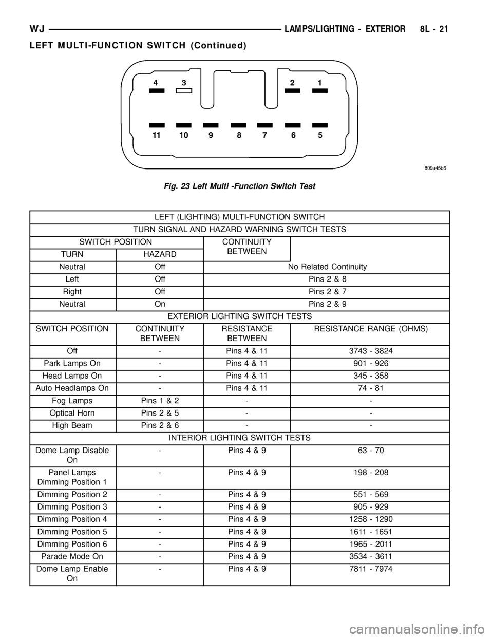
(2) Using an ohmmeter, perform the continuity
and resistance tests at the terminals in the multi-
function switch connector as shown in the Left Multi-
Function Switch Test chart (Fig. 23).
8L - 20 LAMPS/LIGHTING - EXTERIORWJ
LEFT MULTI-FUNCTION SWITCH (Continued)
Page 472 of 2199
LEFT (LIGHTING) MULTI-FUNCTION SWITCH
TURN SIGNAL AND HAZARD WARNING SWITCH TESTS
SWITCH POSITION CONTINUITY
BETWEEN
TURN HAZARD
Neutral Off No Related Continuity
Left Off Pins2&8
Right Off Pins2&7
Neutral On Pins2&9
EXTERIOR LIGHTING SWITCH TESTS
SWITCH POSITION CONTINUITY
BETWEENRESISTANCE
BETWEENRESISTANCE RANGE (OHMS)
Off - Pins4&113743 - 3824
Park Lamps On - Pins4&11 901-926
Head Lamps On - Pins4&11 345-358
Auto Headlamps On - Pins4&11 74-81
Fog Lamps Pins1&2 - -
Optical Horn Pins2&5 - -
High Beam Pins2&6 - -
INTERIOR LIGHTING SWITCH TESTS
Dome Lamp Disable
On- Pins4&9 63-70
Panel Lamps
Dimming Position 1- Pins4&9 198-208
Dimming Position 2 - Pins4&9 551-569
Dimming Position 3 - Pins4&9 905-929
Dimming Position 4 - Pins4&91258 - 1290
Dimming Position 5 - Pins4&9 1611-1651
Dimming Position 6 - Pins4&91965 - 2011
Parade Mode On - Pins4&93534 - 3611
Dome Lamp Enable
On- Pins4&9 7811-7974
Fig. 23 Left Multi -Function Switch Test
WJLAMPS/LIGHTING - EXTERIOR 8L - 21
LEFT MULTI-FUNCTION SWITCH (Continued)
Page 495 of 2199

AMBIENT TEMP SENSOR
DESCRIPTION
Ambient air temperature is monitored by the Elec-
tronic Vehicle Information Center (EVIC) through
ambient temperature messages received from the
Body Control Module (BCM) over the Programmable
Communications Interface (PCI) data bus network.
The BCM receives a hard wired input from the ambi-
ent temperature sensor. The ambient temperature
sensor is a variable resistor mounted to a bracket
that is secured with a screw to the right side of the
headlamp mounting module grille opening, behind
the radiator grille and in front of the engine compart-
ment.
Refer toBody Control Modulein Electronic Con-
trol Modules. For complete circuit diagrams, refer to
the appropriate wiring information. The ambient
temperature sensor cannot be adjusted or repaired
and, if faulty or damaged, it must be replaced.
OPERATION
The ambient temperature sensor is a variable
resistor that operates on a five-volt reference signal
sent to it by the BCM. The resistance in the sensor
changes as temperature changes, changing the tem-
perature sensor signal circuit voltage to the BCM.
Based upon the resistance in the sensor, the BCM
senses a specific voltage on the temperature sensor
signal circuit, which it is programmed to correspond
to a specific temperature. The BCM then sends the
proper ambient temperature messages to the EVIC
over the PCI data bus.
The temperature function is supported by the
ambient temperature sensor, a wiring circuit, the
Body Control Module (BCM), the Programmable
Communications Interface (PCI) data bus, and a por-
tion of the Electronic Vehicle Information Center
(EVIC) module. If any portion of the ambient temper-
ature sensor circuit fails, the BCM will self-diagnose
the circuit. A temperature reading of 130É F will
appear in the EVIC display in place of the tempera-
ture when the sensor circuit is shorted. A tempera-
ture reading of ±40É F will appear in the EVIC
display in place of the temperature when the sensor
circuit is open.
The ambient temperature sensor circuit can also be
diagnosed by referring toDiagnosis and Testing -
Ambient Temperature Sensor, and Diagnosis
and Testing - Ambient Temperature Sensor Cir-
cuit. If the temperature sensor and circuit are con-
firmed to be OK, but the temperature display is
inoperative or incorrect, refer toDiagnosis and
Testing - Electronic Vehicle Information Center
in this group. For complete circuit diagrams, refer to
the appropriate wiring information.
DIAGNOSIS AND TESTING
DIAGNOSIS AND TESTING - AMBIENT
TEMPERATURE SENSOR
(1) Turn the ignition switch to the Off position.
Disconnect and isolate the battery negative cable.
Disconnect the ambient temperature sensor wire har-
ness connector.
(2) Measure the resistance of the ambient temper-
ature sensor. At ±40É C (±40É F), the sensor resis-
tance is 336.6 kilohms. At 60É C (140É F), the sensor
resistance is 2.49 kilohms. The sensor resistance
should read between these two values. If OK, refer to
Diagnosis and Testing - Ambient Temperature
Sensor Circuitin this group. If not OK, replace the
faulty ambient temperature sensor.
DIAGNOSIS AND TESTING - AMBIENT
TEMPERATURE SENSOR CIRCUIT
(1) Turn the ignition switch to the Off position.
Disconnect and isolate the battery negative cable.
Disconnect the 2-way ambient temperature sensor
wire harness connector and the 22-way Body Control
Module (BCM) wire harness connector.
(2) Connect a jumper wire between the two termi-
nals in the body half of the 2-way ambient tempera-
ture sensor wire harness connector.
(3) Check for continuity between the sensor return
circuit and the ambient temperature sensor signal
circuit cavities of the 22-way BCM wire harness con-
nector. There should be continuity. If OK, go to Step
4. If not OK, repair the open sensor return circuit or
ambient temperature sensor signal circuit to the
ambient temperature sensor as required.
(4) Remove the jumper wire from the body half of
the 2-way ambient temperature sensor wire harness
connector. Check for continuity between the sensor
return circuit cavity of the 22-way BCM wire harness
connector and a good ground. There should be no
continuity. If OK, go to Step 5. If not OK, repair the
shorted sensor return circuit as required.
(5) Check for continuity between the ambient tem-
perature sensor signal circuit cavity of the 22-way
BCM wire harness connector and a good ground.
There should be no continuity. If OK, refer toDiag-
nosis and Testing - Electronic Vehicle Informa-
tion Centerin this group. If not OK, repair the
shorted ambient temperature sensor signal circuit as
required.
REMOVAL
(1) Disconnect and isolate the battery negative
cable.
8M - 12 MESSAGE SYSTEMSWJ
Page 519 of 2199
DIAGNOSIS AND TESTING - DRIVER SEAT
SWITCH
For complete circuit diagrams, refer toWiring
Diagrams.
(1) Disconnect and isolate the battery negative
cable.
(2) Remove the power seat switch from the out-
board seat cushion side shield. Refer to the procedure
in this section of the manual.
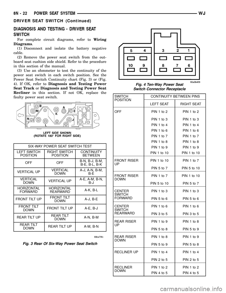
(3) Use an ohmmeter to test the continuity of the
power seat switch in each switch position. See the
Power Seat Switch Continuity chart (Fig. 3) or (Fig.
4). If OK, refer toDiagnosis and Testing Power
Seat TrackorDiagnosis and Testing Power Seat
Reclinerin this section. If not OK, replace the
faulty power seat switch.
SWITCH
POSITIONCONTINUITY BETWEEN PINS
LEFT SEAT RIGHT SEAT
OFF PIN1to2 PIN1to2
PIN1to3 PIN1to3
PIN1to4 PIN1to4
PIN1to6 PIN1to6
PIN1to7 PIN1to7
PIN1to8 PIN1to8
PIN1to9 PIN1to9
PIN1to10 PIN1to10
FRONT RISER
UPPIN1to10 PIN1to7
PIN5to7 PIN5to10
FRONT RISER
DOWNPIN1to7 PIN1to10
PIN5to10 PIN5to7
CENTER
SWITCH
FORWARDPIN1to3 PIN1to3
PIN5to6 PIN5to6
CENTER
SWITCH
REARWARDPIN1to6 PIN1to6
PIN3to5 PIN3to5
REAR RISER
UPPIN1to9 PIN1to8
PIN5to8 PIN5to9
REAR RISER
DOWNPIN1to8 PIN1to9
PIN5to9 PIN5to8
RECLINER UP PIN 1 to 4 PIN 1 to 4
PIN2to5 PIN2to5
RECLINER
DOWNPIN1to2 PIN1to2
PIN4to5 PIN4to5
Fig. 3 Rear Of Six-Way Power Seat Switch
SIX-WAY POWER SEAT SWITCH TEST
LEFT SWITCH
POSITIONRIGHT SWITCH
POSITIONCONTINUITY
BETWEEN
OFF OFFB-N, B-J, B-M,
B-E, B-L, B-K
VERTICAL UPVERTICAL
DOWNA-J, A-N, B-M,
B-E
VERTICAL
DOWNVERTICAL UPA-E, A-M, B-N,
B-J
HORIZONTAL
FORWARDHORIZONTAL
REARWARDA-K, B-L
FRONT TILT UPFRONT TILT
DOWNA-J, B-E
FRONT TILT
DOWNFRONT TILT UP A-E, B-J
REAR TILT UPREAR TILT
DOWNA-N, B-M
REAR TILT
DOWNREAR TILT UP A-M, B-N
Fig. 4 Ten-Way Power Seat
Switch Connector Receptacle
8N - 22 POWER SEAT SYSTEMWJ
DRIVER SEAT SWITCH (Continued)
Page 521 of 2199
LUMBAR CONTROL SWITCH
DESCRIPTION
The ten-way power seat option includes an electri-
cally operated lumbar support mechanism. A single
two-way momentary power lumbar switch is located
on the outboard seat cushion side shield of each front
seat, just forward of the other power seat switches
(Fig. 8). The power lumbar switch is secured to the
back of the seat cushion side shield with two screws,
and the switch paddle protrudes through a hole to
the outside of the shield. The switch paddle is located
in a shallow depression molded into the outer surface
of the seat cushion side shield that helps to shroud it
from unintentional actuation when entering or leav-
ing the vehicle.
The power lumbar switches cannot be adjusted or
repaired and, if faulty or damaged, they must be
replaced.
OPERATION
When the power lumbar switch paddle is actuated,
a battery feed and a ground path are applied through
the switch contacts to the power lumbar adjuster
motor. The motor operates to move the lumbar
adjuster through its drive unit in the selected direc-
tion until the switch is released, or until the travel
limit of the adjuster is reached. When the switch is
moved in the opposite direction, the battery feed and
ground path to the motor are reversed through the
switch contacts. This causes the motor to run in the
opposite direction.
The power lumbar switch should not be held
applied in either direction after the adjuster hasreached its travel limit. The power lumbar adjuster
motor contains a self-resetting circuit breaker to pro-
tect it from overload. However, consecutive or fre-
quent resetting of the circuit breaker must not be
allowed to continue, or the motor may be damaged.
DIAGNOSIS AND TESTING - POWER LUMBAR
SWITCH
For complete circuit diagrams, refer toWiring
Diagrams.
(1) Disconnect and isolate the battery negative
cable.
(2) Remove the power lumbar switch from the out-
board seat cushion side shield. Refer to the procedure
in this section of the manual.
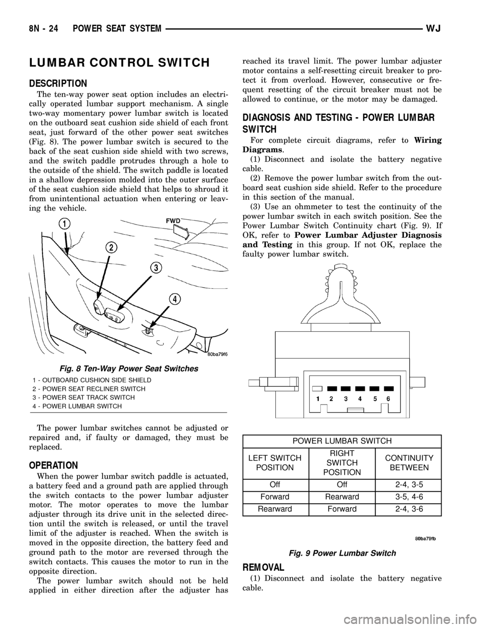
(3) Use an ohmmeter to test the continuity of the
power lumbar switch in each switch position. See the
Power Lumbar Switch Continuity chart (Fig. 9). If
OK, refer toPower Lumbar Adjuster Diagnosis
and Testingin this group. If not OK, replace the
faulty power lumbar switch.
REMOVAL
(1) Disconnect and isolate the battery negative
cable.
Fig. 8 Ten-Way Power Seat Switches
1 - OUTBOARD CUSHION SIDE SHIELD
2 - POWER SEAT RECLINER SWITCH
3 - POWER SEAT TRACK SWITCH
4 - POWER LUMBAR SWITCH
Fig. 9 Power Lumbar Switch
POWER LUMBAR SWITCH
LEFT SWITCH
POSITIONRIGHT
SWITCH
POSITIONCONTINUITY
BETWEEN
Off Off 2-4, 3-5
Forward Rearward 3-5, 4-6
Rearward Forward 2-4, 3-6
8N - 24 POWER SEAT SYSTEMWJ
Page 524 of 2199
(LED) for visibility, and are also color-coded to coin-
cide with the color-coded Driver 1 and Driver 2
Remote Keyless Entry (RKE) transmitters. The
Driver 1 memory switch button and RKE transmitter
are black, and the Driver 2 memory switch button
and RKE transmitter are gray. The memory switch
Set button also has an LED that will illuminate and
flash to indicate that the memory system is in the set
mode. This LED will automatically be extinguished
when a set request has been successfully completed.
See the owner's manual in the vehicle glove box for
more information on the features, use and operation
of the memory switch. For diagnosis of the memory
switch, the DDM or the PCI data bus, the use of a
DRB scan tool and the proper Diagnostic Procedures
manual are recommended.
DIAGNOSIS AND TESTING - MEMORY SWITCH
For complete circuit diagrams, refer toWiring
Diagrams.
(1) Disconnect and isolate the battery negative
cable.
(2) Remove the driver side front door trim panel.
Refer to the Body section for the procedure.
(3) Disconnect the memory switch wire harness
connector from the driver door module connector
receptacle.
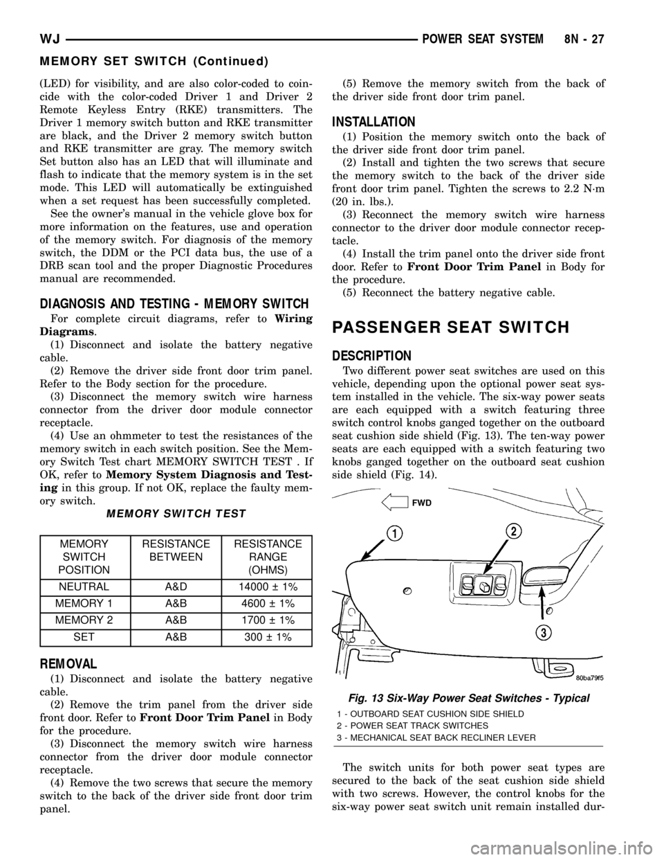
(4) Use an ohmmeter to test the resistances of the
memory switch in each switch position. See the Mem-
ory Switch Test chart MEMORY SWITCH TEST . If
OK, refer toMemory System Diagnosis and Test-
ingin this group. If not OK, replace the faulty mem-
ory switch.
MEMORY SWITCH TEST
MEMORY
SWITCH
POSITIONRESISTANCE
BETWEENRESISTANCE
RANGE
(OHMS)
NEUTRAL A&D 14000 1%
MEMORY 1 A&B 4600 1%
MEMORY 2 A&B 1700 1%
SET A&B 300 1%
REMOVAL
(1) Disconnect and isolate the battery negative
cable.
(2) Remove the trim panel from the driver side
front door. Refer toFront Door Trim Panelin Body
for the procedure.
(3) Disconnect the memory switch wire harness
connector from the driver door module connector
receptacle.
(4) Remove the two screws that secure the memory
switch to the back of the driver side front door trim
panel.(5) Remove the memory switch from the back of
the driver side front door trim panel.
INSTALLATION
(1) Position the memory switch onto the back of
the driver side front door trim panel.
(2) Install and tighten the two screws that secure
the memory switch to the back of the driver side
front door trim panel. Tighten the screws to 2.2 N´m
(20 in. lbs.).
(3) Reconnect the memory switch wire harness
connector to the driver door module connector recep-
tacle.
(4) Install the trim panel onto the driver side front
door. Refer toFront Door Trim Panelin Body for
the procedure.
(5) Reconnect the battery negative cable.
PASSENGER SEAT SWITCH
DESCRIPTION
Two different power seat switches are used on this
vehicle, depending upon the optional power seat sys-
tem installed in the vehicle. The six-way power seats
are each equipped with a switch featuring three
switch control knobs ganged together on the outboard
seat cushion side shield (Fig. 13). The ten-way power
seats are each equipped with a switch featuring two
knobs ganged together on the outboard seat cushion
side shield (Fig. 14).
The switch units for both power seat types are
secured to the back of the seat cushion side shield
with two screws. However, the control knobs for the
six-way power seat switch unit remain installed dur-
Fig. 13 Six-Way Power Seat Switches - Typical
1 - OUTBOARD SEAT CUSHION SIDE SHIELD
2 - POWER SEAT TRACK SWITCHES
3 - MECHANICAL SEAT BACK RECLINER LEVER
WJPOWER SEAT SYSTEM 8N - 27
MEMORY SET SWITCH (Continued)
Page 525 of 2199
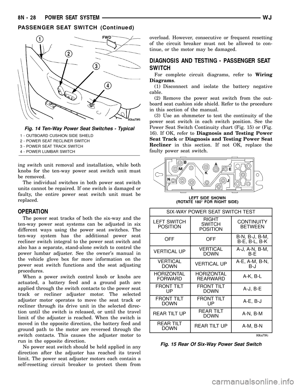
ing switch unit removal and installation, while both
knobs for the ten-way power seat switch unit must
be removed.
The individual switches in both power seat switch
units cannot be repaired. If one switch is damaged or
faulty, the entire power seat switch unit must be
replaced.
OPERATION
The power seat tracks of both the six-way and the
ten-way power seat systems can be adjusted in six
different ways using the power seat switches. The
ten-way system has the additional power seat
recliner switch integral to the power seat switch and
also has a separate, stand-alone switch to control the
power lumbar adjuster. See the owner's manual in
the vehicle glove box for more information on the
power seat switch functions and the seat adjusting
procedures.
When a power switch control knob or knobs are
actuated, a battery feed and a ground path are
applied through the switch contacts to the power seat
track or recliner adjuster motor. The selected
adjuster motor operates to move the seat track or
recliner through its drive unit in the selected direc-
tion until the switch is released, or until the travel
limit of the adjuster is reached. When the switch is
moved in the opposite direction, the battery feed and
ground path to the motor are reversed through the
switch contacts. This causes the adjuster motor to
run in the opposite direction.
No power seat switch should be held applied in any
direction after the adjuster has reached its travel
limit. The power seat adjuster motors each contain a
self-resetting circuit breaker to protect them fromoverload. However, consecutive or frequent resetting
of the circuit breaker must not be allowed to con-
tinue, or the motor may be damaged.
DIAGNOSIS AND TESTING - PASSENGER SEAT
SWITCH
For complete circuit diagrams, refer toWiring
Diagrams.
(1) Disconnect and isolate the battery negative
cable.
(2) Remove the power seat switch from the out-
board seat cushion side shield. Refer to the procedure
in this section of the manual.
(3) Use an ohmmeter to test the continuity of the
power seat switch in each switch position. See the
Power Seat Switch Continuity chart (Fig. 15) or (Fig.
16). If OK, refer toDiagnosis and Testing Power
Seat TrackorDiagnosis and Testing Power Seat
Reclinerin this section. If not OK, replace the
faulty power seat switch.
Fig. 14 Ten-Way Power Seat Switches - Typical
1 - OUTBOARD CUSHION SIDE SHIELD
2 - POWER SEAT RECLINER SWITCH
3 - POWER SEAT TRACK SWITCH
4 - POWER LUMBAR SWITCH
Fig. 15 Rear Of Six-Way Power Seat Switch
SIX-WAY POWER SEAT SWITCH TEST
LEFT SWITCH
POSITIONRIGHT
SWITCH
POSITIONCONTINUITY
BETWEEN
OFF OFFB-N, B-J, B-M,
B-E, B-L, B-K
VERTICAL UPVERTICAL
DOWNA-J, A-N, B-M,
B-E
VERTICAL
DOWNVERTICAL UPA-E, A-M, B-N,
B-J
HORIZONTAL
FORWARDHORIZONTAL
REARWARDA-K, B-L
FRONT TILT
UPFRONT TILT
DOWNA-J, B-E
FRONT TILT
DOWNFRONT TILT
UPA-E, B-J
REAR TILT UPREAR TILT
DOWNA-N, B-M
REAR TILT
DOWNREAR TILT UP A-M, B-N
8N - 28 POWER SEAT SYSTEMWJ
PASSENGER SEAT SWITCH (Continued)
Page 599 of 2199
cylinder lock switches are driven by the key lock cyl-
inders and contain two internal resistors. One resis-
tor value is used for the Lock position, and one for
the Unlock position.
The door cylinder lock switches cannot be adjusted
or repaired and, if faulty or damaged, they must be
replaced.
OPERATION
The door cylinder lock switches are actuated by the
key lock cylinder when the key is inserted in the lock
cylinder and turned to the lock or unlock positions.
The door cylinder lock switch close a circuit between
the door lock switch ground circuit and the left or
right cylinder lock switch mux circuits through one of
two internal resistors for the Driver Door Module
(DDM) when either front door key lock cylinder is in
the Lock, or Unlock positions. The DDM reads the
switch status through an internal pull-up, then uses
this information as an input for the Vehicle Theft
Security System (VTSS) operation.
The door cylinder lock switches and circuits can be
diagnosed using conventional diagnostic tools and
methods.
DIAGNOSIS AND TESTING - DOOR CYLINDER
LOCK SWITCH
Refer to the appropriate wiring information. The
wiring information includes wiring diagrams, proper
wire and connector repair procedures, further details
on wire harness routing and retention, as well as
pin-out and location views for the various wire har-
ness connectors, splices and grounds.(1) Disconnect the door cylinder lock switch pigtail
wire connector from the door wire harness connector.
(2) Using a ohmmeter, check the switch resistance
checks between the two terminals in the door cylin-
der lock switch pigtail wire connector. Actuate the
switch by rotating the key in the door lock cylinder
to test for the proper resistance values in each of the
two switch positions, as shown in the Door Cylinder
Lock Switch Test table.
DOOR CYLINDER LOCK SWITCH TEST
Switch Position Resistance
( 10%)
Left Side Right Side
Lock (Clockwise) Unlock
(Counterclockwise)473 Ohms
Unlock
(Counterclockwise)Lock (Clockwise) 1.994
Kilohms
(3) If a door cylinder lock switch fails either of the
resistance tests, replace the faulty switch.
REMOVAL
(1) Disconnect and isolate the battery negative
cable.
(2) Remove the outside door handle unit from the
outer door panel. (Refer to 23 - BODY/DOOR -
FRONT/EXTERIOR HANDLE - REMOVAL).
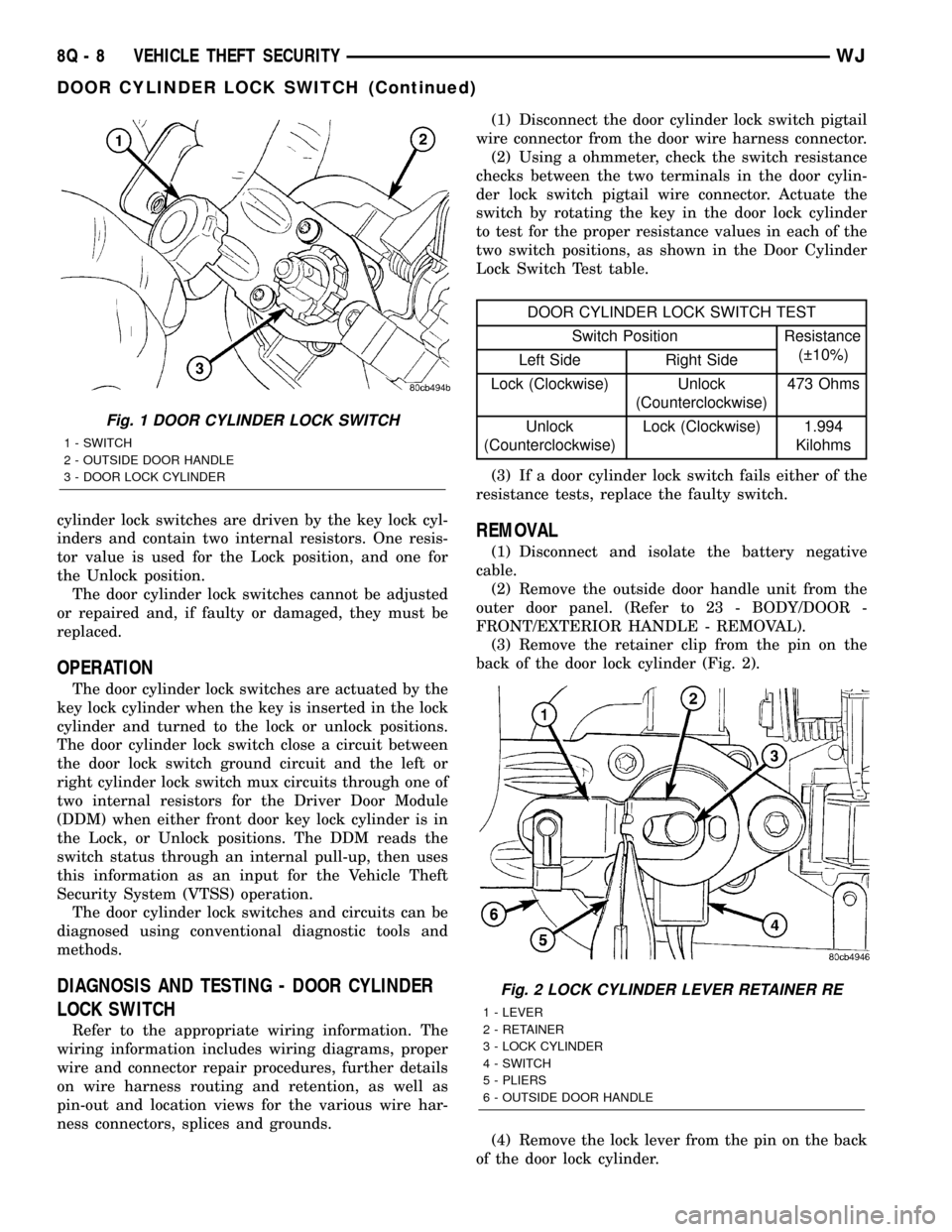
(3) Remove the retainer clip from the pin on the
back of the door lock cylinder (Fig. 2).
(4) Remove the lock lever from the pin on the back
of the door lock cylinder.
Fig. 1 DOOR CYLINDER LOCK SWITCH
1 - SWITCH
2 - OUTSIDE DOOR HANDLE
3 - DOOR LOCK CYLINDER
Fig. 2 LOCK CYLINDER LEVER RETAINER RE
1 - LEVER
2 - RETAINER
3 - LOCK CYLINDER
4 - SWITCH
5 - PLIERS
6 - OUTSIDE DOOR HANDLE
8Q - 8 VEHICLE THEFT SECURITYWJ
DOOR CYLINDER LOCK SWITCH (Continued)
Page 629 of 2199

function switch provides a resistor multiplexed out-
put to the Body Control Module (BCM) on a
windshield wiper switch mux circuit, and the BCM
responds by energizing the wiper on/off relay in the
Power Distribution Center (PDC) to operate the front
wiper motor momentarily at low speed to provide the
front wiper mist mode.
²Intermittent Front Wipe Mode- On models
not equipped with the optional automatic wiper sys-
tem, the control knob on the end of the right (wiper)
multi-function switch control stalk is rotated to one
of five minor intermediate detents to select the
desired intermittent front wipe delay interval. The
control knob is rotated rearward (counterclockwise)
to increase the delay, or forward (clockwise) to
decrease the delay. The right (wiper) multi-function
switch provides a resistor multiplexed output to the
Body Control Module (BCM) on a windshield wiper
switch mux circuit. The BCM responds by monitoring
electronic vehicle speed messages received from the
Powertrain Control Module (PCM) over the Program-
mable Communications Interface (PCI) data bus,
then energizing the wiper on/off relay in the Power
Distribution Center (PDC) to operate the front wiper
motor at the proper delay intervals.
²Intermittent Rear Wipe Mode- The control
ring on the right (wiper) multi-function switch con-
trol stalk is rotated to the center detent to select the
intermittent rear wiper mode. The right (wiper)
multi-function switch provides a battery current out-
put to the rear wiper motor on a rear wiper motor
delay control circuit to signal the rear wiper module
to operate the rear wiper in the intermittent wipe
mode.
²Rear Washer Mode- The right (wiper) multi-
function switch control stalk is pushed forward
toward the instrument panel to a momentary posi-
tions to activate the rear washer pump/motor in the
rear washer mode. The rear washer pump will con-
tinue to operate in the rear washer mode until the
control stalk is released. The right (wiper) multi-
function switch provides battery current on a rear
washer pump motor control circuit to energize the
rear washer pump in the rear washer mode.DIAGNOSIS AND TESTING - RIGHT MULTI-
FUNCTION SWITCH
Be certain to perform the diagnosis for the front
wiper system, front washer system, rear wiper sys-
tem, and/or rear washer system before testing the
right multi-function switch. (Refer to 8 - ELECTRI-
CAL/FRONT WIPERS/WASHERS - DIAGNOSIS
AND TESTING) or (Refer to 8 - ELECTRICAL/REAR
WIPERS/WASHERS - DIAGNOSIS AND TESTING).
Refer to the appropriate wiring information. The wir-
ing information includes wiring diagrams, proper
wire and connector repair procedures, details of wire
harness routing and retention, connector pin-out
information and location views for the various wire
harness connectors, splices and grounds.
WARNING: ON VEHICLES EQUIPPED WITH AIR-
BAGS, DISABLE THE PASSIVE RESTRAINT SYS-
TEM BEFORE ATTEMPTING ANY STEERING
WHEEL, STEERING COLUMN, DRIVER AIRBAG,
PASSENGER AIRBAG. SIDE CURTAIN AIRBAG,
FRONT IMPACT SENSOR, SIDE IMPACT SENSOR,
OR INSTRUMENT PANEL COMPONENT DIAGNOSIS
OR SERVICE. DISCONNECT AND ISOLATE THE
BATTERY NEGATIVE (GROUND) CABLE, THEN
WAIT TWO MINUTES FOR THE SYSTEM CAPACI-
TOR TO DISCHARGE BEFORE PERFORMING FUR-
THER DIAGNOSIS OR SERVICE. THIS IS THE ONLY
SURE WAY TO DISABLE THE PASSIVE RESTRAINT
SYSTEM. FAILURE TO TAKE THE PROPER PRE-
CAUTIONS COULD RESULT IN ACCIDENTAL AIR-
BAG DEPLOYMENT AND POSSIBLE PERSONAL
INJURY.
(1) Disconnect and isolate the battery negative
cable.
(2) Remove the right multi-function switch from
the steering column and disconnect the instrument
panel wire harness connector for the switch from the
switch connector receptacle.
(3) Using an ohmmeter, check the right multi-func-
tion switch continuity and resistances at the switch
terminals as shown in the Right Multi-Function
Switch test chart (Fig. 17).
8R - 22 FRONT WIPERS/WASHERSWJ
RIGHT MULTI-FUNCTION SWITCH (Continued)