window lock JEEP GRAND CHEROKEE 2002 WJ / 2.G Owner's Guide
[x] Cancel search | Manufacturer: JEEP, Model Year: 2002, Model line: GRAND CHEROKEE, Model: JEEP GRAND CHEROKEE 2002 WJ / 2.GPages: 2199, PDF Size: 76.01 MB
Page 1178 of 2199
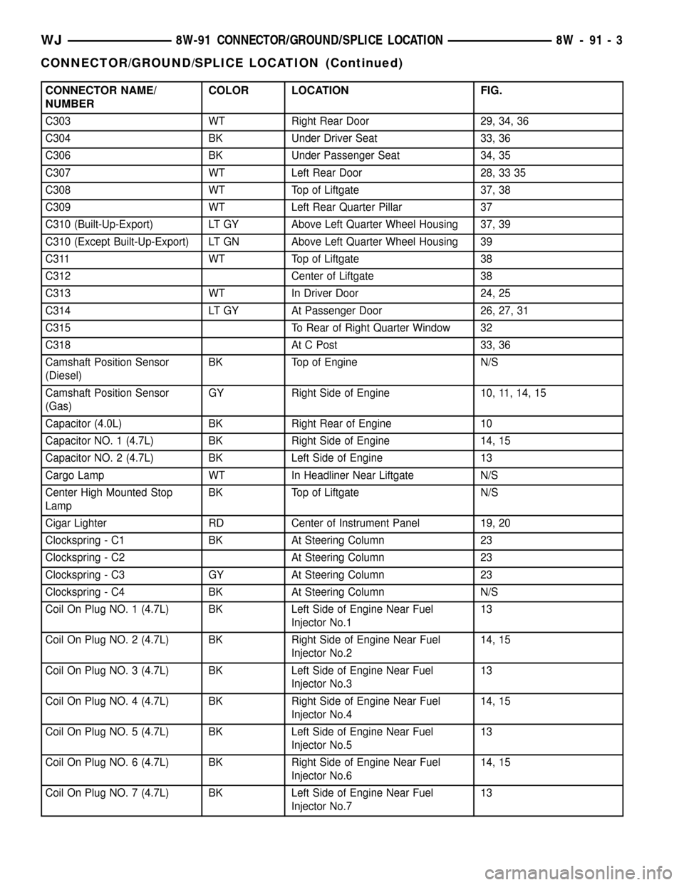
CONNECTOR NAME/
NUMBERCOLOR LOCATION FIG.
C303 WT Right Rear Door 29, 34, 36
C304 BK Under Driver Seat 33, 36
C306 BK Under Passenger Seat 34, 35
C307 WT Left Rear Door 28, 33 35
C308 WT Top of Liftgate 37, 38
C309 WT Left Rear Quarter Pillar 37
C310 (Built-Up-Export) LT GY Above Left Quarter Wheel Housing 37, 39
C310 (Except Built-Up-Export) LT GN Above Left Quarter Wheel Housing 39
C311 WT Top of Liftgate 38
C312 Center of Liftgate 38
C313 WT In Driver Door 24, 25
C314 LT GY At Passenger Door 26, 27, 31
C315 To Rear of Right Quarter Window 32
C318 At C Post 33, 36
Camshaft Position Sensor
(Diesel)BK Top of Engine N/S
Camshaft Position Sensor
(Gas)GY Right Side of Engine 10, 11, 14, 15
Capacitor (4.0L) BK Right Rear of Engine 10
Capacitor NO. 1 (4.7L) BK Right Side of Engine 14, 15
Capacitor NO. 2 (4.7L) BK Left Side of Engine 13
Cargo Lamp WT In Headliner Near Liftgate N/S
Center High Mounted Stop
LampBK Top of Liftgate N/S
Cigar Lighter RD Center of Instrument Panel 19, 20
Clockspring - C1 BK At Steering Column 23
Clockspring - C2 At Steering Column 23
Clockspring - C3 GY At Steering Column 23
Clockspring - C4 BK At Steering Column N/S
Coil On Plug NO. 1 (4.7L) BK Left Side of Engine Near Fuel
Injector No.113
Coil On Plug NO. 2 (4.7L) BK Right Side of Engine Near Fuel
Injector No.214, 15
Coil On Plug NO. 3 (4.7L) BK Left Side of Engine Near Fuel
Injector No.313
Coil On Plug NO. 4 (4.7L) BK Right Side of Engine Near Fuel
Injector No.414, 15
Coil On Plug NO. 5 (4.7L) BK Left Side of Engine Near Fuel
Injector No.513
Coil On Plug NO. 6 (4.7L) BK Right Side of Engine Near Fuel
Injector No.614, 15
Coil On Plug NO. 7 (4.7L) BK Left Side of Engine Near Fuel
Injector No.713
WJ8W-91 CONNECTOR/GROUND/SPLICE LOCATION 8W - 91 - 3
CONNECTOR/GROUND/SPLICE LOCATION (Continued)
Page 1179 of 2199
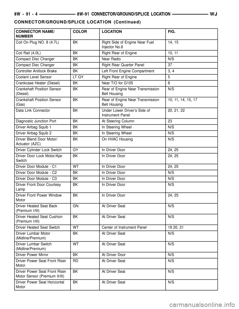
CONNECTOR NAME/
NUMBERCOLOR LOCATION FIG.
Coil On Plug NO. 8 (4.7L) BK Right Side of Engine Near Fuel
Injector No.814, 15
Coil Rail (4.0L) BK Right Rear of Engine 10, 11
Compact Disc Changer BK Near Radio N/S
Compact Disc Changer BK Right Rear Quarter Panel 37
Controller Antilock Brake BK Left Front Engine Compartment 3, 4
Coolant Level Sensor LT GY Right Rear of Engine 5
Crankcase Heater (Diesel) BK Near T/O for G105 8
Crankshaft Position Sensor
(Diesel)BK Rear of Engine Near Transmission
Bell HousingN/S
Crankshaft Position Sensor
(Gas)BK Rear of Engine Near Transmission
Bell Housing10, 11, 14, 15, 17
Data Link Connector BK Under Lower Driver's Side of
Instrument Panel20, 21, 22
Diagnostic Junction Port BK At Steering Column 23
Driver Airbag Squib 1 BK In Steering Wheel N/S
Driver Airbag Squib 2 BK In Steering Wheel N/S
Driver Blend Door Motor/
Actuator (AZC)BK On HVAC Housing N/S
Driver Cylinder Lock Switch GY In Driver Door 24, 25
Driver Door Lock Motor/Ajar
SwitchBK In Driver Door 24, 25
Driver Door Module - C1 WT In Driver Door 24, 25
Driver Door Module - C2 BK In Driver Door N/S
Driver Door Module - C3 BK In Driver Door N/S
Driver Front Door Courtesy
LampBK In Driver Door N/S
Driver Front Power Window
MotorBK In Driver Door 24, 25
Driver Heated Seat Back
(Premium I/III)GN At Driver Seat N/S
Driver Heated Seat Cushion
(Premium I/III)BK At Driver Seat N/S
Driver Heated Seat Switch WT Center of Instrument Panel 19 20, 21
Driver Lumbar Motor
(Midline/Premium)BK At Driver Seat N/S
Driver Lumbar Switch
(Midline/Premium)WT At Driver Seat N/S
Driver Power Mirror BK At Driver Door N/S
Driver Power Seat Front Riser
MotorRD At Driver Seat N/S
Driver Power Seat Front Riser
Motor Sensor (Premium II/III)BK At Driver Seat N/S
Driver Power Seat Horizontal
MotorBK At Driver Seat N/S
8W - 91 - 4 8W-91 CONNECTOR/GROUND/SPLICE LOCATIONWJ
CONNECTOR/GROUND/SPLICE LOCATION (Continued)
Page 1180 of 2199
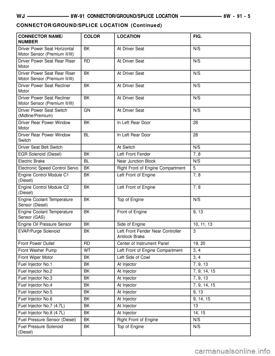
CONNECTOR NAME/
NUMBERCOLOR LOCATION FIG.
Driver Power Seat Horizontal
Motor Sensor (Premium II/III)BK At Driver Seat N/S
Driver Power Seat Rear Riser
MotorRD At Driver Seat N/S
Driver Power Seat Rear Riser
Motor Sensor (Premium II/III)BK At Driver Seat N/S
Driver Power Seat Recliner
MotorBK At Driver Seat N/S
Driver Power Seat Recliner
Motor Sensor (Premium II/III)BK At Driver Seat N/S
Driver Power Seat Switch
(Midline/Premium)GN At Driver Seat N/S
Driver Rear Power Window
MotorBK In Left Rear Door 28
Driver Rear Power Window
SwitchBL In Left Rear Door 28
Driver Seat Belt Switch At Switch N/S
EGR Solenoid (Diesel) BK Left Front Fender 7, 8
Electric Brake BL Near Junction Block N/S
Electronic Speed Control Servo BK Right Front of Engine Compartment 5
Engine Control Module C1
(Diesel)BK Left Front of Engine 7, 8
Engine Control Module C2
(Diesel)BK Left Front of Engine 7, 8
Engine Coolant Temperature
Sensor (Diesel)BK Top of Engine N/S
Engine Coolant Temperature
Sensor (GAS)BK Front of Engine 9, 13
Engine Oil Pressure Sensor BK Side of Engine 10, 11, 13
EVAP/Purge Solenoid BK Left Front Fender Near Controller
Antilock Brake3
Front Power Outlet RD Center of Instrument Panel 19, 20
Front Washer Pump WT Left Front of Engine Compartment 3, 4
Front Wiper Motor BK Left Side of Cowl 3, 4
Fuel Injector No.1 BK At Injector 7, 9, 13
Fuel Injector No.2 BK At Injector 7, 9, 14, 15
Fuel Injector No.3 BK At Injector 7, 9, 13
Fuel Injector No.4 BK At Injector 7, 9, 14, 15
Fuel Injector No.5 BK At Injector 9, 13
Fuel Injector No.6 BK At Injector 9, 14, 15
Fuel Injector No.7 (4.7L) BK At Injector 13
Fuel Injector No.8 (4.7L) BK At Injector 14, 15
Fuel Pressure Sensor (Diesel) BK Right Front of Engine N/S
Fuel Pressure Solenoid
(Diesel)BK Top of Engine N/S
WJ8W-91 CONNECTOR/GROUND/SPLICE LOCATION 8W - 91 - 5
CONNECTOR/GROUND/SPLICE LOCATION (Continued)
Page 1183 of 2199
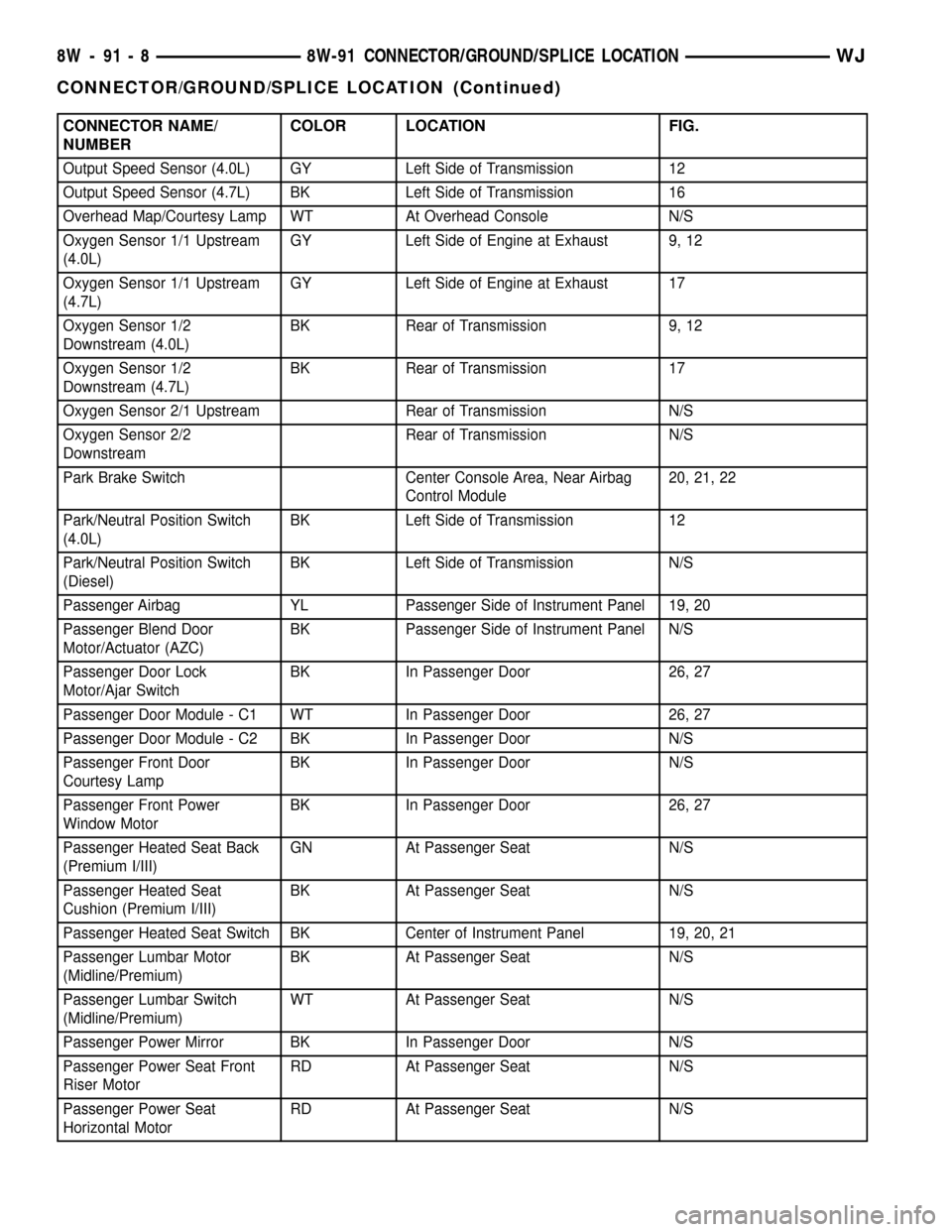
CONNECTOR NAME/
NUMBERCOLOR LOCATION FIG.
Output Speed Sensor (4.0L) GY Left Side of Transmission 12
Output Speed Sensor (4.7L) BK Left Side of Transmission 16
Overhead Map/Courtesy Lamp WT At Overhead Console N/S
Oxygen Sensor 1/1 Upstream
(4.0L)GY Left Side of Engine at Exhaust 9, 12
Oxygen Sensor 1/1 Upstream
(4.7L)GY Left Side of Engine at Exhaust 17
Oxygen Sensor 1/2
Downstream (4.0L)BK Rear of Transmission 9, 12
Oxygen Sensor 1/2
Downstream (4.7L)BK Rear of Transmission 17
Oxygen Sensor 2/1 Upstream Rear of Transmission N/S
Oxygen Sensor 2/2
DownstreamRear of Transmission N/S
Park Brake Switch Center Console Area, Near Airbag
Control Module20, 21, 22
Park/Neutral Position Switch
(4.0L)BK Left Side of Transmission 12
Park/Neutral Position Switch
(Diesel)BK Left Side of Transmission N/S
Passenger Airbag YL Passenger Side of Instrument Panel 19, 20
Passenger Blend Door
Motor/Actuator (AZC)BK Passenger Side of Instrument Panel N/S
Passenger Door Lock
Motor/Ajar SwitchBK In Passenger Door 26, 27
Passenger Door Module - C1 WT In Passenger Door 26, 27
Passenger Door Module - C2 BK In Passenger Door N/S
Passenger Front Door
Courtesy LampBK In Passenger Door N/S
Passenger Front Power
Window MotorBK In Passenger Door 26, 27
Passenger Heated Seat Back
(Premium I/III)GN At Passenger Seat N/S
Passenger Heated Seat
Cushion (Premium I/III)BK At Passenger Seat N/S
Passenger Heated Seat Switch BK Center of Instrument Panel 19, 20, 21
Passenger Lumbar Motor
(Midline/Premium)BK At Passenger Seat N/S
Passenger Lumbar Switch
(Midline/Premium)WT At Passenger Seat N/S
Passenger Power Mirror BK In Passenger Door N/S
Passenger Power Seat Front
Riser MotorRD At Passenger Seat N/S
Passenger Power Seat
Horizontal MotorRD At Passenger Seat N/S
8W - 91 - 8 8W-91 CONNECTOR/GROUND/SPLICE LOCATIONWJ
CONNECTOR/GROUND/SPLICE LOCATION (Continued)
Page 1191 of 2199
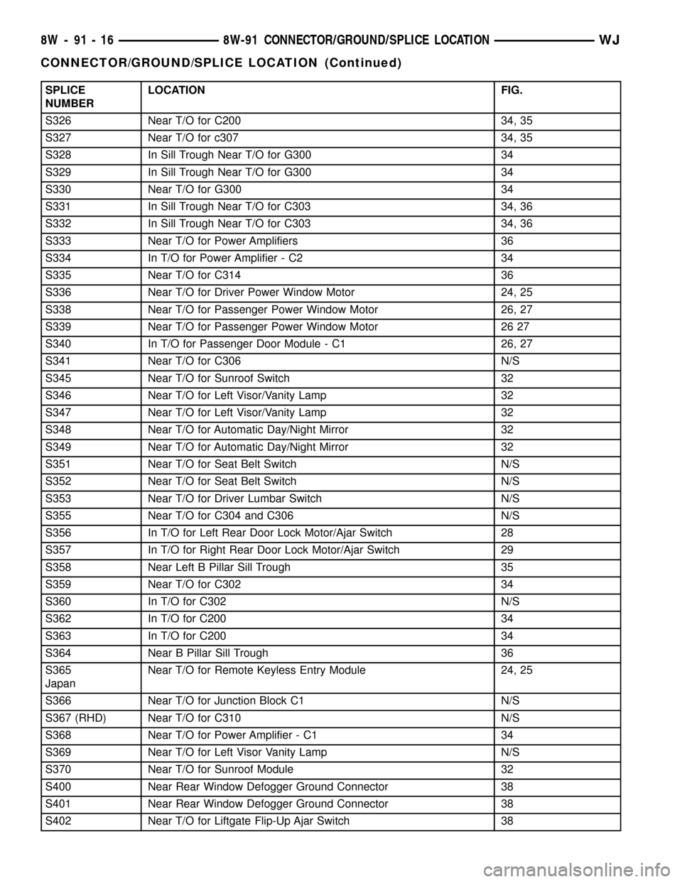
SPLICE
NUMBERLOCATION FIG.
S326 Near T/O for C200 34, 35
S327 Near T/O for c307 34, 35
S328 In Sill Trough Near T/O for G300 34
S329 In Sill Trough Near T/O for G300 34
S330 Near T/O for G300 34
S331 In Sill Trough Near T/O for C303 34, 36
S332 In Sill Trough Near T/O for C303 34, 36
S333 Near T/O for Power Amplifiers 36
S334 In T/O for Power Amplifier - C2 34
S335 Near T/O for C314 36
S336 Near T/O for Driver Power Window Motor 24, 25
S338 Near T/O for Passenger Power Window Motor 26, 27
S339 Near T/O for Passenger Power Window Motor 26 27
S340 In T/O for Passenger Door Module - C1 26, 27
S341 Near T/O for C306 N/S
S345 Near T/O for Sunroof Switch 32
S346 Near T/O for Left Visor/Vanity Lamp 32
S347 Near T/O for Left Visor/Vanity Lamp 32
S348 Near T/O for Automatic Day/Night Mirror 32
S349 Near T/O for Automatic Day/Night Mirror 32
S351 Near T/O for Seat Belt Switch N/S
S352 Near T/O for Seat Belt Switch N/S
S353 Near T/O for Driver Lumbar Switch N/S
S355 Near T/O for C304 and C306 N/S
S356 In T/O for Left Rear Door Lock Motor/Ajar Switch 28
S357 In T/O for Right Rear Door Lock Motor/Ajar Switch 29
S358 Near Left B Pillar Sill Trough 35
S359 Near T/O for C302 34
S360 In T/O for C302 N/S
S362 In T/O for C200 34
S363 In T/O for C200 34
S364 Near B Pillar Sill Trough 36
S365
JapanNear T/O for Remote Keyless Entry Module 24, 25
S366 Near T/O for Junction Block C1 N/S
S367 (RHD) Near T/O for C310 N/S
S368 Near T/O for Power Amplifier - C1 34
S369 Near T/O for Left Visor Vanity Lamp N/S
S370 Near T/O for Sunroof Module 32
S400 Near Rear Window Defogger Ground Connector 38
S401 Near Rear Window Defogger Ground Connector 38
S402 Near T/O for Liftgate Flip-Up Ajar Switch 38
8W - 91 - 16 8W-91 CONNECTOR/GROUND/SPLICE LOCATIONWJ
CONNECTOR/GROUND/SPLICE LOCATION (Continued)
Page 1876 of 2199
(2) Apply silicone lubricant to a cloth and wipe it
on door seals to avoid over-spray that can soil pas-
senger's clothing.
(3) Before applying lubricant, the component
should be wiped clean. After lubrication, any excess
lubricant should be removed.
(4) The hood latch, latch release mechanism, latch
striker, and safety latch should be lubricated period-
ically.
(5) The door lock cylinders should be lubricated
twice each year (preferably autumn and spring).
(a) Spray a small amount of lock cylinder lubri-
cant directly into the lock cylinder.
(b) Apply a small amount to the key and insert
it into the lock cylinder.
(c) Rotate it to the locked position and then back
to the unlocked position several times.(d) Remove the key. Wipe the lubricant from it
with a clean cloth to avoid soiling of clothing.
STANDARD PROCEDURE - DRILLING AND
WELDING
When holes must be drilled or punched in an inner
body panel, verify depth of space to the outer body
panel, electrical wiring, or other components. Dam-
age to vehicle can result.
Do not weld exterior panels unless combustible
material on the interior of vehicle is removed from
the repair area. Fire or hazardous conditions, can
result.
Always have a fire extinguisher ready for use when
welding.
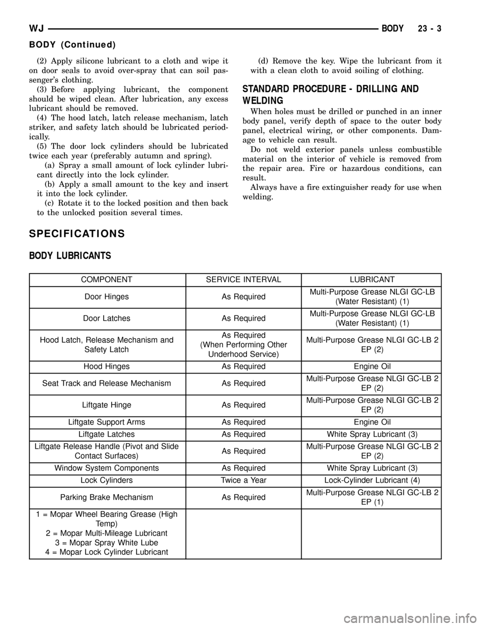
SPECIFICATIONS
BODY LUBRICANTS
COMPONENT SERVICE INTERVAL LUBRICANT
Door Hinges As RequiredMulti-Purpose Grease NLGI GC-LB
(Water Resistant) (1)
Door Latches As RequiredMulti-Purpose Grease NLGI GC-LB
(Water Resistant) (1)
Hood Latch, Release Mechanism and
Safety LatchAs Required
(When Performing Other
Underhood Service)Multi-Purpose Grease NLGI GC-LB 2
EP (2)
Hood Hinges As Required Engine Oil
Seat Track and Release Mechanism As RequiredMulti-Purpose Grease NLGI GC-LB 2
EP (2)
Liftgate Hinge As RequiredMulti-Purpose Grease NLGI GC-LB 2
EP (2)
Liftgate Support Arms As Required Engine Oil
Liftgate Latches As Required White Spray Lubricant (3)
Liftgate Release Handle (Pivot and Slide
Contact Surfaces)As RequiredMulti-Purpose Grease NLGI GC-LB 2
EP (2)
Window System Components As Required White Spray Lubricant (3)
Lock Cylinders Twice a Year Lock-Cylinder Lubricant (4)
Parking Brake Mechanism As RequiredMulti-Purpose Grease NLGI GC-LB 2
EP (1)
1 = Mopar Wheel Bearing Grease (High
Temp)
2 = Mopar Multi-Mileage Lubricant
3 = Mopar Spray White Lube
4 = Mopar Lock Cylinder Lubricant
WJBODY 23 - 3
BODY (Continued)
Page 1884 of 2199
DOOR - FRONT
TABLE OF CONTENTS
page page
CHECK STRAP
REMOVAL.............................11
INSTALLATION.........................11
DOOR
REMOVAL.............................12
INSTALLATION.........................12
ADJUSTMENTS
DOOR ADJUSTMENT..................12
DOOR GLASS
REMOVAL.............................12
INSTALLATION.........................12
EXTERIOR HANDLE
REMOVAL.............................13
INSTALLATION.........................13
GLASS RUN CHANNEL
REMOVAL.............................13
INSTALLATION.........................14
HINGE
REMOVAL.............................14
INSTALLATION.........................15
INSIDE HANDLE ACTUATOR
REMOVAL.............................15INSTALLATION.........................15
LATCH
REMOVAL.............................15
INSTALLATION.........................15
ADJUSTMENTS
DOOR LATCH........................16
LATCH STRIKER
REMOVAL.............................16
INSTALLATION.........................16
LOCK CYLINDER
REMOVAL.............................16
INSTALLATION.........................17
TRIM PANEL
REMOVAL.............................17
INSTALLATION.........................17
WATERDAM
REMOVAL.............................17
INSTALLATION.........................17
WINDOW REGULATOR
REMOVAL.............................18
INSTALLATION.........................18
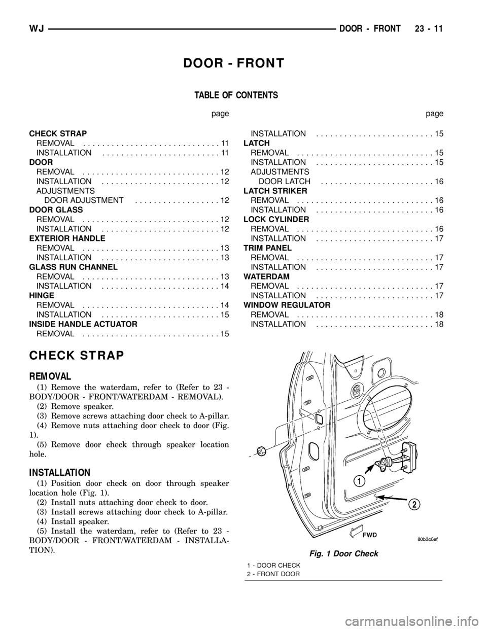
CHECK STRAP
REMOVAL
(1) Remove the waterdam, refer to (Refer to 23 -
BODY/DOOR - FRONT/WATERDAM - REMOVAL).
(2) Remove speaker.
(3) Remove screws attaching door check to A-pillar.
(4) Remove nuts attaching door check to door (Fig.
1).
(5) Remove door check through speaker location
hole.
INSTALLATION
(1) Position door check on door through speaker
location hole (Fig. 1).
(2) Install nuts attaching door check to door.
(3) Install screws attaching door check to A-pillar.
(4) Install speaker.
(5) Install the waterdam, refer to (Refer to 23 -
BODY/DOOR - FRONT/WATERDAM - INSTALLA-
TION).
Fig. 1 Door Check
1 - DOOR CHECK
2 - FRONT DOOR
WJDOOR - FRONT 23 - 11
Page 1893 of 2199
DOOR
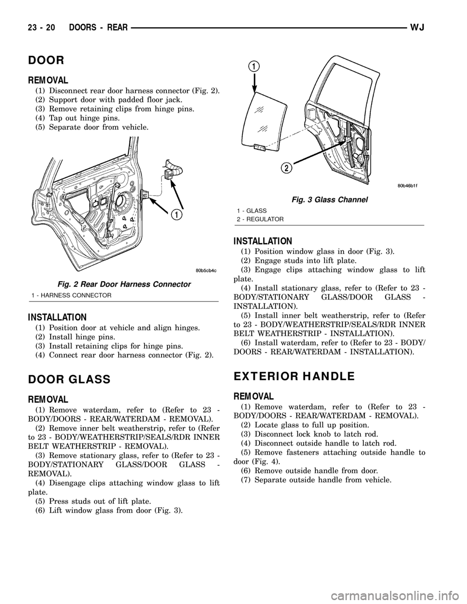
REMOVAL
(1) Disconnect rear door harness connector (Fig. 2).
(2) Support door with padded floor jack.
(3) Remove retaining clips from hinge pins.
(4) Tap out hinge pins.
(5) Separate door from vehicle.
INSTALLATION
(1) Position door at vehicle and align hinges.
(2) Install hinge pins.
(3) Install retaining clips for hinge pins.
(4) Connect rear door harness connector (Fig. 2).
DOOR GLASS
REMOVAL
(1) Remove waterdam, refer to (Refer to 23 -
BODY/DOORS - REAR/WATERDAM - REMOVAL).
(2) Remove inner belt weatherstrip, refer to (Refer
to 23 - BODY/WEATHERSTRIP/SEALS/RDR INNER
BELT WEATHERSTRIP - REMOVAL).
(3) Remove stationary glass, refer to (Refer to 23 -
BODY/STATIONARY GLASS/DOOR GLASS -
REMOVAL).
(4) Disengage clips attaching window glass to lift
plate.
(5) Press studs out of lift plate.
(6) Lift window glass from door (Fig. 3).
INSTALLATION
(1) Position window glass in door (Fig. 3).
(2) Engage studs into lift plate.
(3) Engage clips attaching window glass to lift
plate.
(4) Install stationary glass, refer to (Refer to 23 -
BODY/STATIONARY GLASS/DOOR GLASS -
INSTALLATION).
(5) Install inner belt weatherstrip, refer to (Refer
to 23 - BODY/WEATHERSTRIP/SEALS/RDR INNER
BELT WEATHERSTRIP - INSTALLATION).
(6) Install waterdam, refer to (Refer to 23 - BODY/
DOORS - REAR/WATERDAM - INSTALLATION).
EXTERIOR HANDLE
REMOVAL
(1) Remove waterdam, refer to (Refer to 23 -
BODY/DOORS - REAR/WATERDAM - REMOVAL).
(2) Locate glass to full up position.
(3) Disconnect lock knob to latch rod.
(4) Disconnect outside handle to latch rod.
(5) Remove fasteners attaching outside handle to
door (Fig. 4).
(6) Remove outside handle from door.
(7) Separate outside handle from vehicle.
Fig. 2 Rear Door Harness Connector
1 - HARNESS CONNECTOR
Fig. 3 Glass Channel
1 - GLASS
2 - REGULATOR
23 - 20 DOORS - REARWJ
Page 1967 of 2199
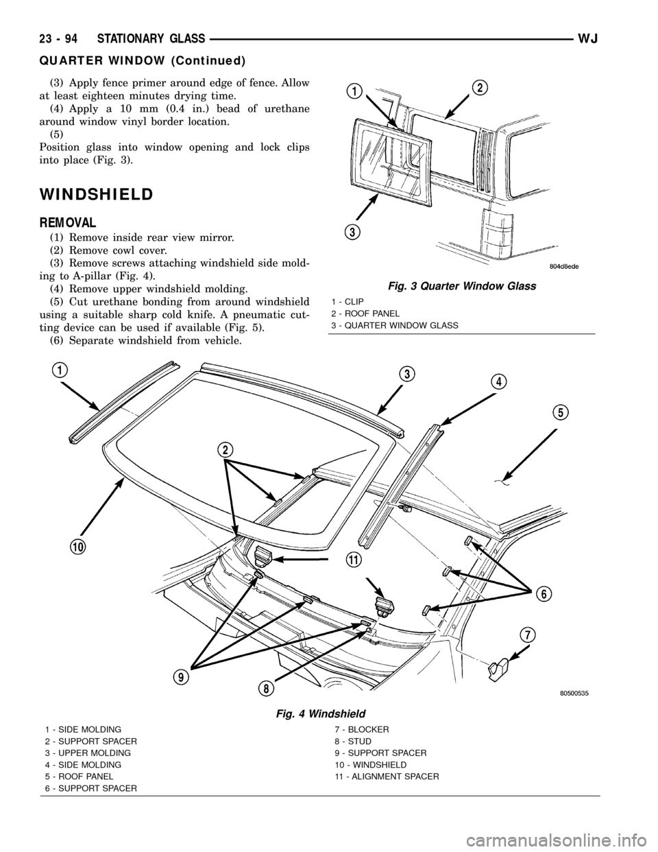
(3) Apply fence primer around edge of fence. Allow
at least eighteen minutes drying time.
(4) Apply a 10 mm (0.4 in.) bead of urethane
around window vinyl border location.
(5)
Position glass into window opening and lock clips
into place (Fig. 3).
WINDSHIELD
REMOVAL
(1) Remove inside rear view mirror.
(2) Remove cowl cover.
(3) Remove screws attaching windshield side mold-
ing to A-pillar (Fig. 4).
(4) Remove upper windshield molding.
(5) Cut urethane bonding from around windshield
using a suitable sharp cold knife. A pneumatic cut-
ting device can be used if available (Fig. 5).
(6) Separate windshield from vehicle.
Fig. 3 Quarter Window Glass
1 - CLIP
2 - ROOF PANEL
3 - QUARTER WINDOW GLASS
Fig. 4 Windshield
1 - SIDE MOLDING
2 - SUPPORT SPACER
3 - UPPER MOLDING
4 - SIDE MOLDING
5 - ROOF PANEL
6 - SUPPORT SPACER7 - BLOCKER
8 - STUD
9 - SUPPORT SPACER
10 - WINDSHIELD
11 - ALIGNMENT SPACER
23 - 94 STATIONARY GLASSWJ
QUARTER WINDOW (Continued)
Page 1968 of 2199
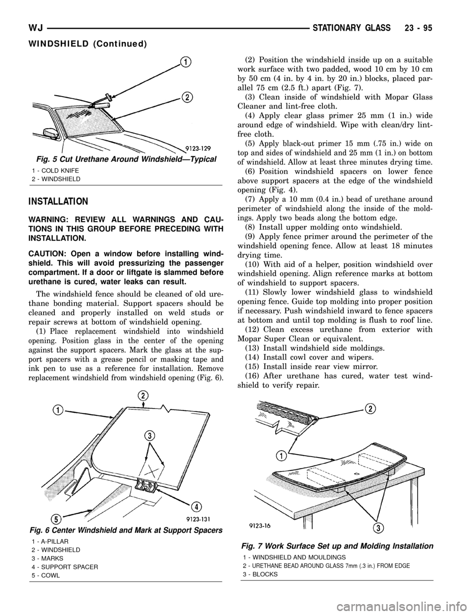
INSTALLATION
WARNING: REVIEW ALL WARNINGS AND CAU-
TIONS IN THIS GROUP BEFORE PRECEDING WITH
INSTALLATION.
CAUTION: Open a window before installing wind-
shield. This will avoid pressurizing the passenger
compartment. If a door or liftgate is slammed before
urethane is cured, water leaks can result.
The windshield fence should be cleaned of old ure-
thane bonding material. Support spacers should be
cleaned and properly installed on weld studs or
repair screws at bottom of windshield opening.
(1)
Place replacement windshield into windshield
opening. Position glass in the center of the opening
against the support spacers. Mark the glass at the sup-
port spacers with a grease pencil or masking tape and
ink pen to use as a reference for installation. Remove
replacement windshield from windshield opening (Fig. 6).
(2) Position the windshield inside up on a suitable
work surface with two padded, wood 10 cm by 10 cm
by 50 cm (4 in. by 4 in. by 20 in.) blocks, placed par-
allel 75 cm (2.5 ft.) apart (Fig. 7).
(3) Clean inside of windshield with Mopar Glass
Cleaner and lint-free cloth.
(4) Apply clear glass primer 25 mm (1 in.) wide
around edge of windshield. Wipe with clean/dry lint-
free cloth.
(5)
Apply black-out primer 15 mm (.75 in.) wide on
top and sides of windshield and 25 mm (1 in.) on bottom
of windshield. Allow at least three minutes drying time.
(6) Position windshield spacers on lower fence
above support spacers at the edge of the windshield
opening (Fig. 4).
(7)
Apply a 10 mm (0.4 in.) bead of urethane around
perimeter of windshield along the inside of the mold-
ings. Apply two beads along the bottom edge.
(8) Install upper molding onto windshield.
(9) Apply fence primer around the perimeter of the
windshield opening fence. Allow at least 18 minutes
drying time.
(10) With aid of a helper, position windshield over
windshield opening. Align reference marks at bottom
of windshield to support spacers.
(11) Slowly lower windshield glass to windshield
opening fence. Guide top molding into proper position
if necessary. Push windshield inward to fence spacers
at bottom and until top molding is flush to roof line.
(12) Clean excess urethane from exterior with
Mopar Super Clean or equivalent.
(13) Install windshield side moldings.
(14) Install cowl cover and wipers.
(15) Install inside rear view mirror.
(16) After urethane has cured, water test wind-
shield to verify repair.
Fig. 6 Center Windshield and Mark at Support Spacers
1 - A-PILLAR
2 - WINDSHIELD
3 - MARKS
4 - SUPPORT SPACER
5 - COWLFig. 7 Work Surface Set up and Molding Installation
1 - WINDSHIELD AND MOULDINGS
2-
URETHANE BEAD AROUND GLASS 7mm (.3 in.) FROM EDGE
3 - BLOCKS
Fig. 5 Cut Urethane Around WindshieldÐTypical
1 - COLD KNIFE
2 - WINDSHIELD
WJSTATIONARY GLASS 23 - 95
WINDSHIELD (Continued)