JEEP GRAND CHEROKEE 2003 WJ / 2.G Workshop Manual
Manufacturer: JEEP, Model Year: 2003, Model line: GRAND CHEROKEE, Model: JEEP GRAND CHEROKEE 2003 WJ / 2.GPages: 2199, PDF Size: 76.01 MB
Page 1411 of 2199

Page 1412 of 2199
FRAME & BUMPERS
TABLE OF CONTENTS
page page
FRONT ABSORBER
REMOVAL.............................1
INSTALLATION..........................1
FRONT FASCIA
REMOVAL.............................1
INSTALLATION..........................1
REAR ABSORBER
REMOVAL.............................2
INSTALLATION..........................2
REAR FASCIA
REMOVAL.............................2
INSTALLATION..........................4
FRAME
SPECIFICATIONS
SPECIFICATIONS - TORQUE.............4
FRAME DIMENSIONS...................4
FRONT SKID PLATE
REMOVAL.............................7INSTALLATION..........................7
FRONT TOW HOOK
REMOVAL.............................7
INSTALLATION..........................7
FUEL TANK SKID PLATE
DESCRIPTION..........................7
REAR TOW HOOK
REMOVAL.............................7
INSTALLATION..........................7
TRAILER HITCH
REMOVAL.............................8
INSTALLATION..........................8
TRANSFER CASE SKID PLATE
REMOVAL.............................8
INSTALLATION..........................8
FRONT ABSORBER
REMOVAL
(1) Remove front fascia, refer to (Refer to 13 -
FRAMES & BUMPERS/BUMPERS/FRONT FASCIA
- REMOVAL).
(2) Remove the retainer attaching the absorber to
the fascia.
(3) Separate the absorber from the fascia.
INSTALLATION
(1) Position the absorber on the fascia.
(2) Install the retainer attaching the absorber to
the fascia.
(3) Install front fascia. Refer to (Refer to 13 -
FRAMES & BUMPERS/BUMPERS/FRONT FASCIA
- INSTALLATION).
FRONT FASCIA
REMOVAL
(1) Raise and support vehicle.
(2) Turn front wheels to access rivets and remove
plastic rivets attaching fascia to wheel liner.
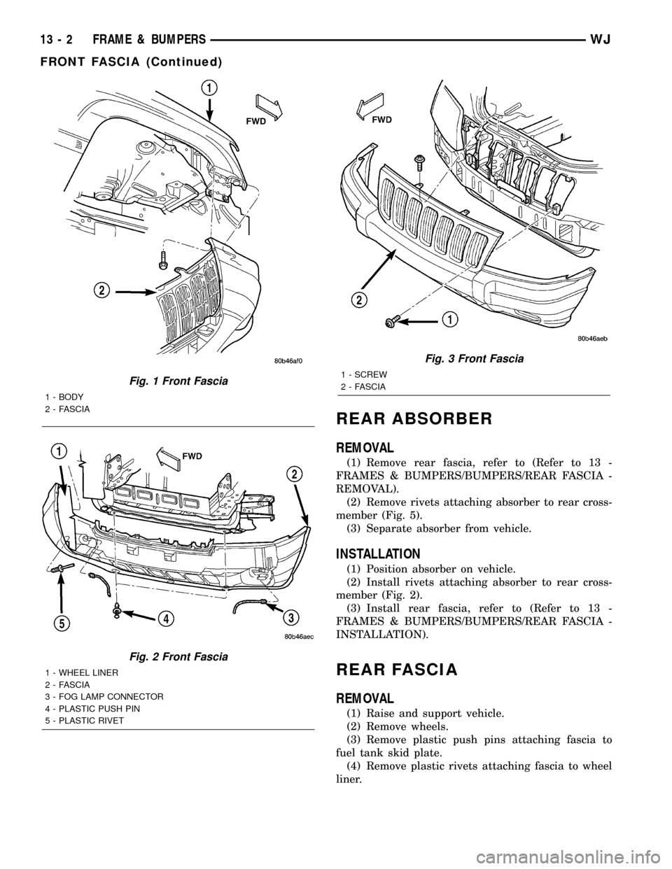
(3) Remove bolts attaching fascia to fender (Fig. 1).(4) Remove plastic push pin fasteners attaching
front fascia to lower radiator crossmember splash
shield (Fig. 2).
(5) Disengage fog lamp connectors, if equipped.
(6) Remove screws attaching fascia/grille to upper
radiator crossmember (Fig. 3).
(7) Slide fascia forward to separate from vehicle.
INSTALLATION
(1) Slide fascia onto vehicle engaging fascia with
tabs on bottom of front fenders.
(2) Install screws attaching fascia/grille to upper
radiator crossmember (Fig. 3).
(3) Install bolts attaching fascia to fender (Fig. 1).
(4) Engage fog lamp connectors, if equipped.
(5) Install plastic rivets attaching fascia to wheel
liner.
(6) Install plastic push pin fasteners attaching
front fascia to lower radiator crossmember splash
shield (Fig. 2).
(7) Remove supports and lower vehicle.
WJFRAME & BUMPERS 13 - 1
Page 1413 of 2199
REAR ABSORBER
REMOVAL
(1) Remove rear fascia, refer to (Refer to 13 -
FRAMES & BUMPERS/BUMPERS/REAR FASCIA -
REMOVAL).
(2) Remove rivets attaching absorber to rear cross-
member (Fig. 5).
(3) Separate absorber from vehicle.
INSTALLATION
(1) Position absorber on vehicle.
(2) Install rivets attaching absorber to rear cross-
member (Fig. 2).
(3) Install rear fascia, refer to (Refer to 13 -
FRAMES & BUMPERS/BUMPERS/REAR FASCIA -
INSTALLATION).
REAR FASCIA
REMOVAL
(1) Raise and support vehicle.
(2) Remove wheels.
(3) Remove plastic push pins attaching fascia to
fuel tank skid plate.
(4) Remove plastic rivets attaching fascia to wheel
liner.
Fig. 1 Front Fascia
1 - BODY
2 - FASCIA
Fig. 2 Front Fascia
1 - WHEEL LINER
2 - FASCIA
3 - FOG LAMP CONNECTOR
4 - PLASTIC PUSH PIN
5 - PLASTIC RIVET
Fig. 3 Front Fascia
1 - SCREW
2 - FASCIA
13 - 2 FRAME & BUMPERSWJ
FRONT FASCIA (Continued)
Page 1414 of 2199
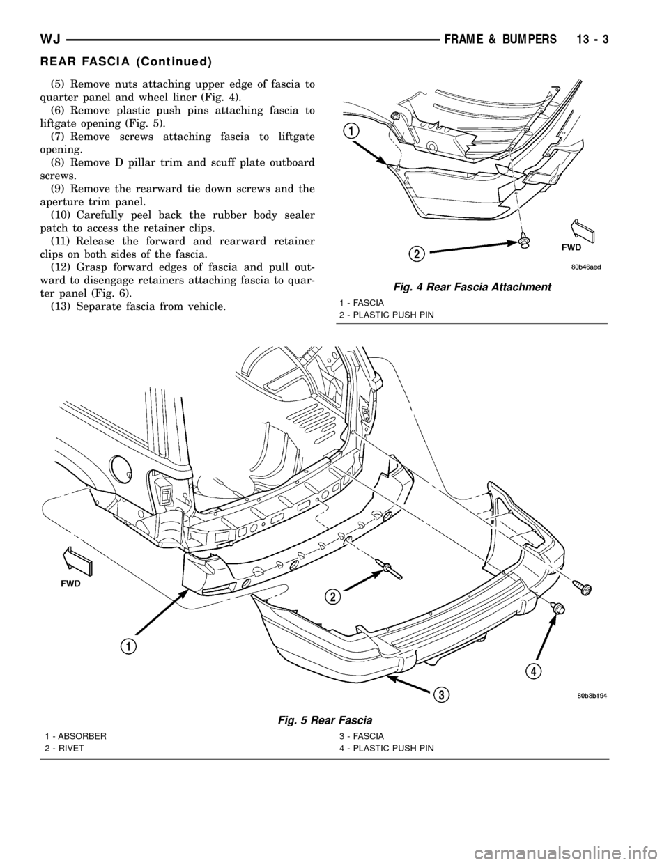
(5) Remove nuts attaching upper edge of fascia to
quarter panel and wheel liner (Fig. 4).
(6) Remove plastic push pins attaching fascia to
liftgate opening (Fig. 5).
(7) Remove screws attaching fascia to liftgate
opening.
(8) Remove D pillar trim and scuff plate outboard
screws.
(9) Remove the rearward tie down screws and the
aperture trim panel.
(10) Carefully peel back the rubber body sealer
patch to access the retainer clips.
(11) Release the forward and rearward retainer
clips on both sides of the fascia.
(12) Grasp forward edges of fascia and pull out-
ward to disengage retainers attaching fascia to quar-
ter panel (Fig. 6).
(13) Separate fascia from vehicle.
Fig. 5 Rear Fascia
1 - ABSORBER
2 - RIVET3 - FASCIA
4 - PLASTIC PUSH PIN
Fig. 4 Rear Fascia Attachment
1 - FASCIA
2 - PLASTIC PUSH PIN
WJFRAME & BUMPERS 13 - 3
REAR FASCIA (Continued)
Page 1415 of 2199
INSTALLATION
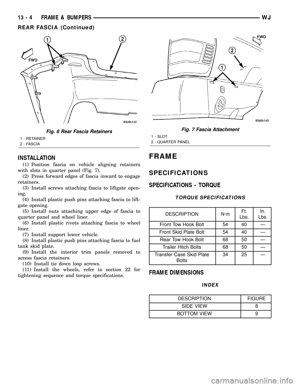
(1) Position fascia on vehicle aligning retainers
with slots in quarter panel (Fig. 7).
(2) Press forward edges of fascia inward to engage
retainers.
(3) Install screws attaching fascia to liftgate open-
ing.
(4) Install plastic push pins attaching fascia to lift-
gate opening.
(5) Install nuts attaching upper edge of fascia to
quarter panel and wheel liner.
(6) Install plastic rivets attaching fascia to wheel
liner.
(7) Install support lower vehicle.
(8) Install plastic push pins attaching fascia to fuel
tank skid plate.
(9) Install the interior trim panels removed to
access fascia retainers.
(10) Install tie down loop screws.
(11) Install the wheels, refer to section 22 for
tightening sequence and torque specifications.
FRAME
SPECIFICATIONS
SPECIFICATIONS - TORQUE
TORQUE SPECIFICATIONS
DESCRIPTION N´mFt.
Lbs.In.
Lbs.
Front Tow Hook Bolt 54 40 Ð
Front Skid Plate Bolt 54 40 Ð
Rear Tow Hook Bolt 68 50 Ð
Trailer Hitch Bolts 68 50 Ð
Transfer Case Skid Plate
Bolts34 25 Ð
FRAME DIMENSIONS
INDEX
DESCRIPTION FIGURE
SIDE VIEW 8
BOTTOM VIEW 9
Fig. 6 Rear Fascia Retainers
1 - RETAINER
2 - FASCIA
Fig. 7 Fascia Attachment
1 - SLOT
2 - QUARTER PANEL
13 - 4 FRAME & BUMPERSWJ
REAR FASCIA (Continued)
Page 1416 of 2199
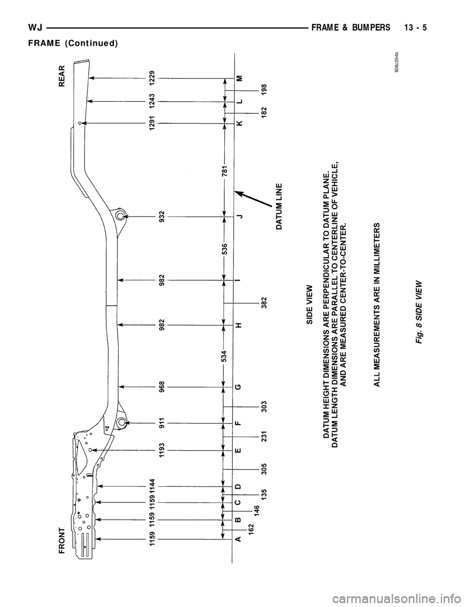
Fig. 8 SIDE VIEW
WJFRAME & BUMPERS 13 - 5
FRAME (Continued)
Page 1417 of 2199
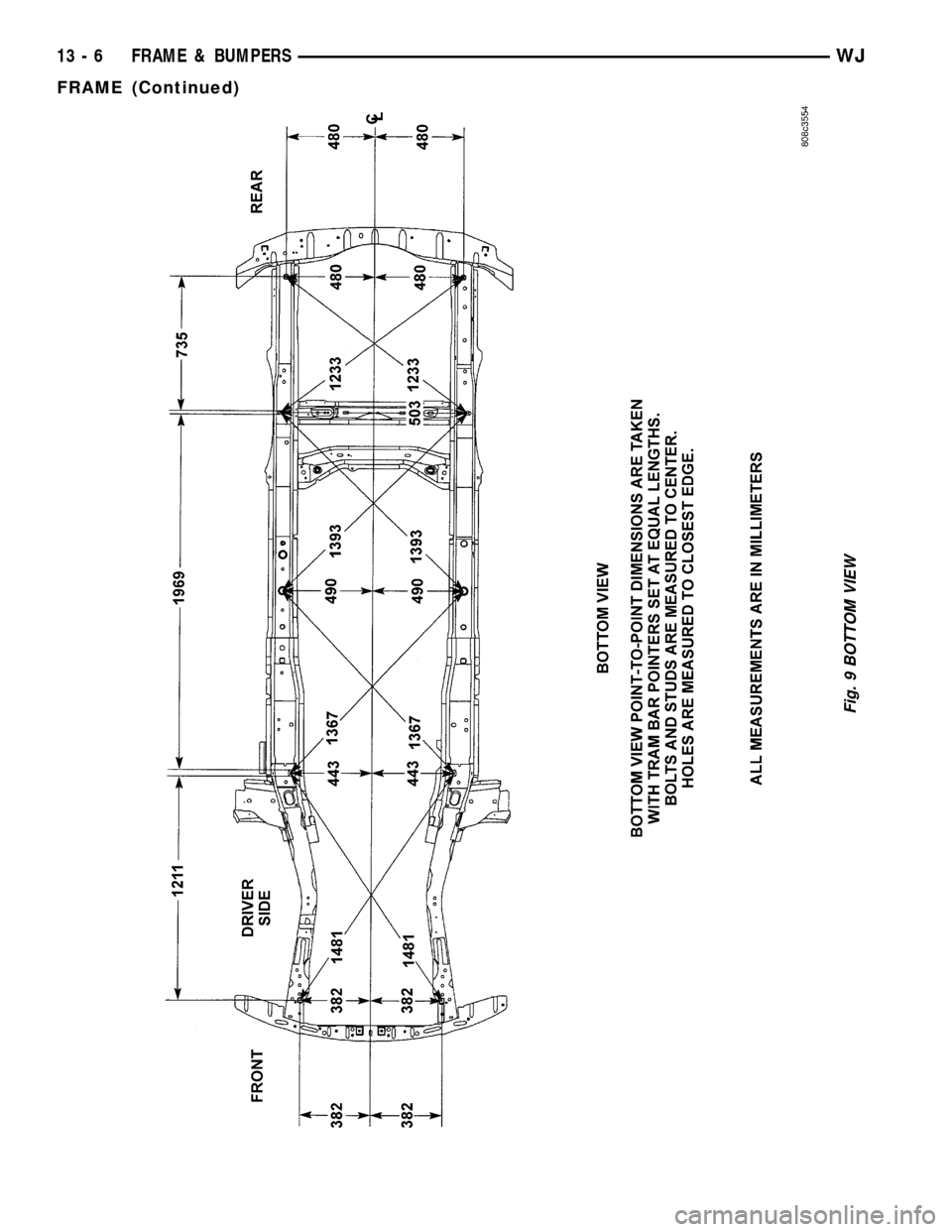
Fig. 9 BOTTOM VIEW
13 - 6 FRAME & BUMPERSWJ
FRAME (Continued)
Page 1418 of 2199
FRONT SKID PLATE
REMOVAL
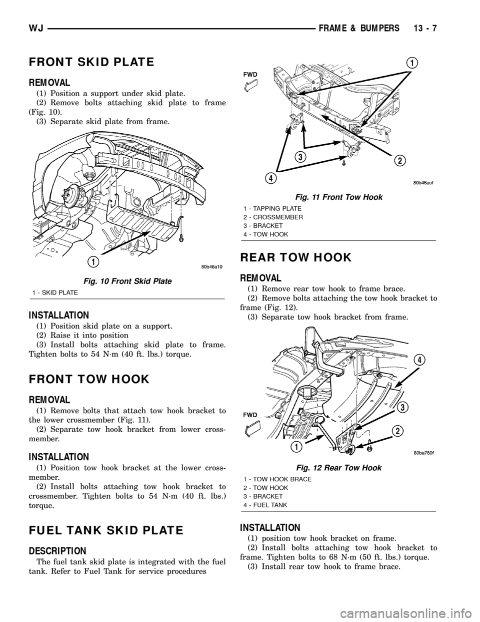
(1) Position a support under skid plate.
(2) Remove bolts attaching skid plate to frame
(Fig. 10).
(3) Separate skid plate from frame.
INSTALLATION
(1) Position skid plate on a support.
(2) Raise it into position
(3) Install bolts attaching skid plate to frame.
Tighten bolts to 54 N´m (40 ft. lbs.) torque.
FRONT TOW HOOK
REMOVAL
(1) Remove bolts that attach tow hook bracket to
the lower crossmember (Fig. 11).
(2) Separate tow hook bracket from lower cross-
member.
INSTALLATION
(1) Position tow hook bracket at the lower cross-
member.
(2) Install bolts attaching tow hook bracket to
crossmember. Tighten bolts to 54 N´m (40 ft. lbs.)
torque.
FUEL TANK SKID PLATE
DESCRIPTION
The fuel tank skid plate is integrated with the fuel
tank. Refer to Fuel Tank for service procedures
REAR TOW HOOK
REMOVAL
(1) Remove rear tow hook to frame brace.
(2) Remove bolts attaching the tow hook bracket to
frame (Fig. 12).
(3) Separate tow hook bracket from frame.
INSTALLATION
(1) position tow hook bracket on frame.
(2) Install bolts attaching tow hook bracket to
frame. Tighten bolts to 68 N´m (50 ft. lbs.) torque.
(3) Install rear tow hook to frame brace.
Fig. 10 Front Skid Plate
1 - SKID PLATE
Fig. 11 Front Tow Hook
1 - TAPPING PLATE
2 - CROSSMEMBER
3 - BRACKET
4 - TOW HOOK
Fig. 12 Rear Tow Hook
1 - TOW HOOK BRACE
2 - TOW HOOK
3 - BRACKET
4 - FUEL TANK
WJFRAME & BUMPERS 13 - 7
Page 1419 of 2199
TRAILER HITCH
REMOVAL
(1) Remove rear fascia, refer to (Refer to 13 -
FRAMES & BUMPERS/BUMPERS/REAR FASCIA -
REMOVAL).
(2) Remove screws attaching trailer harness plug
to trailer hitch.
(3) Disconnect harness connector from harness
plug.
(4) Position support stands under trailer hitch.
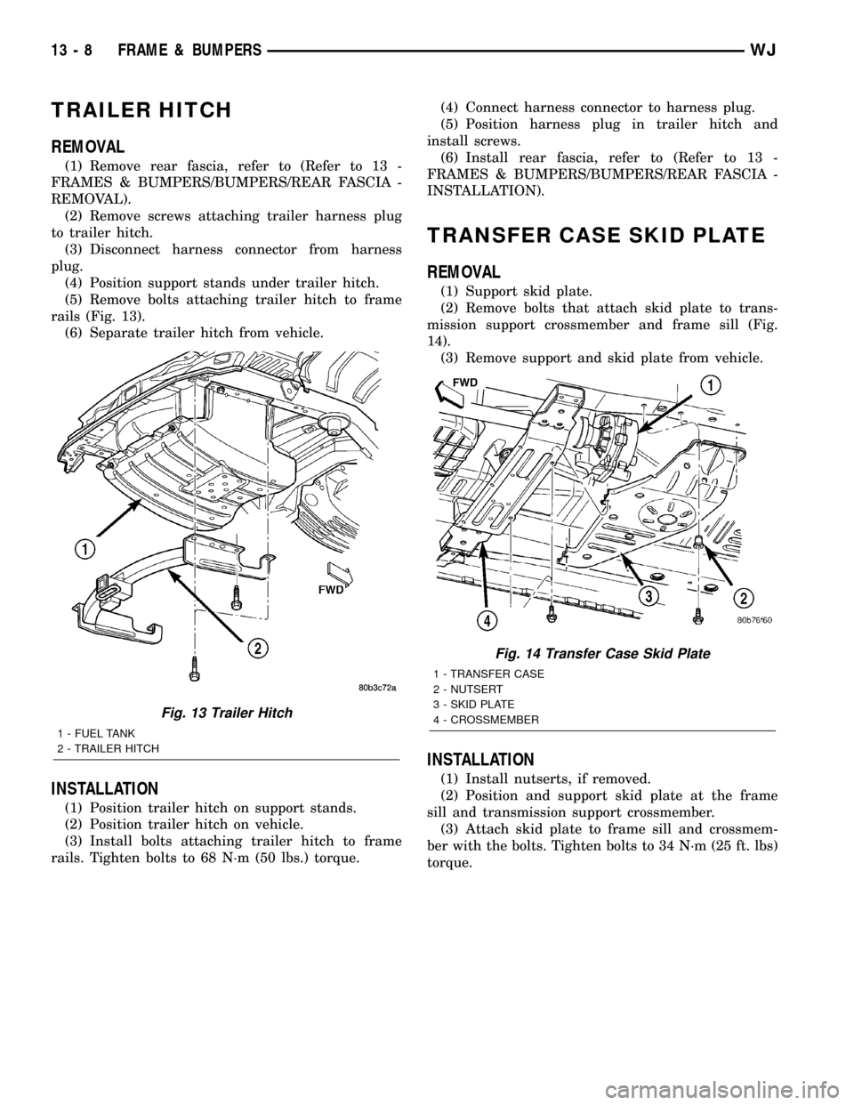
(5) Remove bolts attaching trailer hitch to frame
rails (Fig. 13).
(6) Separate trailer hitch from vehicle.
INSTALLATION
(1) Position trailer hitch on support stands.
(2) Position trailer hitch on vehicle.
(3) Install bolts attaching trailer hitch to frame
rails. Tighten bolts to 68 N´m (50 lbs.) torque.(4) Connect harness connector to harness plug.
(5) Position harness plug in trailer hitch and
install screws.
(6) Install rear fascia, refer to (Refer to 13 -
FRAMES & BUMPERS/BUMPERS/REAR FASCIA -
INSTALLATION).
TRANSFER CASE SKID PLATE
REMOVAL
(1) Support skid plate.
(2) Remove bolts that attach skid plate to trans-
mission support crossmember and frame sill (Fig.
14).
(3) Remove support and skid plate from vehicle.
INSTALLATION
(1) Install nutserts, if removed.
(2) Position and support skid plate at the frame
sill and transmission support crossmember.
(3) Attach skid plate to frame sill and crossmem-
ber with the bolts. Tighten bolts to 34 N´m (25 ft. lbs)
torque.
Fig. 13 Trailer Hitch
1 - FUEL TANK
2 - TRAILER HITCH
Fig. 14 Transfer Case Skid Plate
1 - TRANSFER CASE
2 - NUTSERT
3 - SKID PLATE
4 - CROSSMEMBER
13 - 8 FRAME & BUMPERSWJ
Page 1420 of 2199
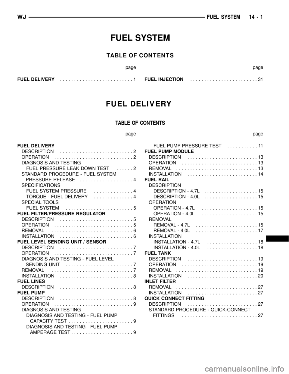
FUEL SYSTEM
TABLE OF CONTENTS
page page
FUEL DELIVERY..........................1FUEL INJECTION........................31
FUEL DELIVERY
TABLE OF CONTENTS
page page
FUEL DELIVERY
DESCRIPTION..........................2
OPERATION............................2
DIAGNOSIS AND TESTING
FUEL PRESSURE LEAK DOWN TEST......2
STANDARD PROCEDURE - FUEL SYSTEM
PRESSURE RELEASE...................4
SPECIFICATIONS
FUEL SYSTEM PRESSURE..............4
TORQUE - FUEL DELIVERY..............4
SPECIAL TOOLS
FUEL SYSTEM........................5
FUEL FILTER/PRESSURE REGULATOR
DESCRIPTION..........................5
OPERATION............................5
REMOVAL.............................6
INSTALLATION..........................6
FUEL LEVEL SENDING UNIT / SENSOR
DESCRIPTION..........................7
OPERATION............................7
DIAGNOSIS AND TESTING - FUEL LEVEL
SENDING UNIT........................7
REMOVAL.............................7
INSTALLATION..........................8
FUEL LINES
DESCRIPTION..........................8
FUEL PUMP
DESCRIPTION..........................8
OPERATION............................9
DIAGNOSIS AND TESTING
DIAGNOSIS AND TESTING - FUEL PUMP
CAPACITY TEST.......................9
DIAGNOSIS AND TESTING - FUEL PUMP
AMPERAGE TEST......................9FUEL PUMP PRESSURE TEST...........11
FUEL PUMP MODULE
DESCRIPTION.........................13
OPERATION...........................13
REMOVAL.............................13
INSTALLATION.........................14
FUEL RAIL
DESCRIPTION
DESCRIPTION - 4.7L...................15
DESCRIPTION - 4.0L...................15
OPERATION
OPERATION - 4.7L....................15
OPERATION - 4.0L....................15
REMOVAL
REMOVAL - 4.7L......................15
REMOVAL - 4.0L......................17
INSTALLATION
INSTALLATION - 4.7L..................18
INSTALLATION - 4.0L..................18
FUEL TANK
DESCRIPTION.........................19
OPERATION...........................19
REMOVAL.............................19
INSTALLATION.........................20
INLET FILTER
REMOVAL.............................27
INSTALLATION.........................27
QUICK CONNECT FITTING
DESCRIPTION.........................27
STANDARD PROCEDURE - QUICK-CONNECT
FITTINGS...........................27
WJFUEL SYSTEM 14 - 1