Fill location JEEP GRAND CHEROKEE 2003 WJ / 2.G Workshop Manual
[x] Cancel search | Manufacturer: JEEP, Model Year: 2003, Model line: GRAND CHEROKEE, Model: JEEP GRAND CHEROKEE 2003 WJ / 2.GPages: 2199, PDF Size: 76.01 MB
Page 12 of 2199
LUBRICATION & MAINTENANCE
TABLE OF CONTENTS
page page
LUBRICATION & MAINTENANCE
SPECIFICATIONS - FLUID CAPACITIES.......1
INTERNATIONAL SYMBOLS
DESCRIPTION..........................2
PARTS & LUBRICANT RECOMMENDATION
STANDARD PROCEDURE - PARTS &
LUBRICANT RECOMMENDATIONS.........2
FLUID TYPES
DESCRIPTION
DESCRIPTION - ENGINE COOLANT........2
DESCRIPTION - ENGINE COOLANT........3
ENGINE OIL..........................4
DESCRIPTION - ENGINE OIL.............4
DESCRIPTION........................5
DESCRIPTION - TRANSFER CASE - NV242 . . 5
DESCRIPTION - TRANSFER CASE - NV247 . . 5
DESCRIPTION - AUTOMATIC
TRANSMISSION FLUID..................5
DESCRIPTION - ENGINE OIL - DIESEL
ENGINES............................6OPERATION - AUTOMATIC TRANSMISSION
FLUID...............................6
FLUID FILL/CHECK LOCATIONS
INSPECTION - FLUID FILL/CHECK
LOCATIONS..........................6
MAINTENANCE SCHEDULES
DESCRIPTION..........................6
LIFT POINTS
STANDARD PROCEDURE - HOISTING AND
JACKING RECOMMENDATIONS...........6
JUMP STARTING
STANDARD PROCEDURE - JUMP STARTING . . 7
EMERGENCY TOW HOOKS
DESCRIPTION..........................8
TOWING
STANDARD PROCEDURE - TOWING
RECOMMENDATIONS...................8
LUBRICATION &
MAINTENANCE
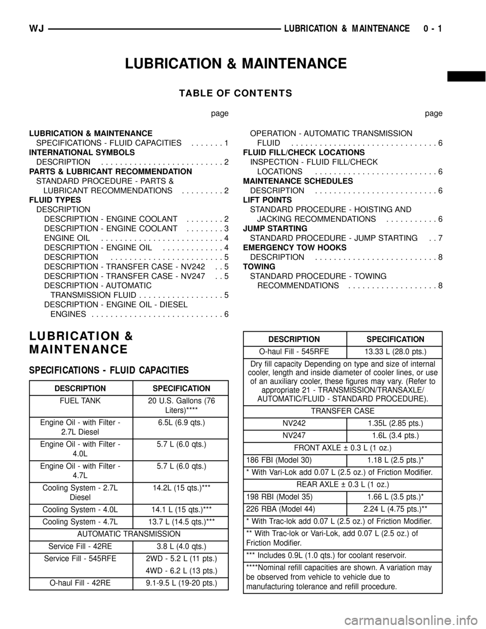
SPECIFICATIONS - FLUID CAPACITIES
DESCRIPTION SPECIFICATION
FUEL TANK 20 U.S. Gallons (76
Liters)****
Engine Oil - with Filter -
2.7L Diesel6.5L (6.9 qts.)
Engine Oil - with Filter -
4.0L5.7 L (6.0 qts.)
Engine Oil - with Filter -
4.7L5.7 L (6.0 qts.)
Cooling System - 2.7L
Diesel14.2L (15 qts.)***
Cooling System - 4.0L 14.1 L (15 qts.)***
Cooling System - 4.7L 13.7 L (14.5 qts.)***
AUTOMATIC TRANSMISSION
Service Fill - 42RE 3.8 L (4.0 qts.)
Service Fill - 545RFE 2WD - 5.2 L (11 pts.)
4WD - 6.2 L (13 pts.)
O-haul Fill - 42RE 9.1-9.5 L (19-20 pts.)
DESCRIPTION SPECIFICATION
O-haul Fill - 545RFE 13.33 L (28.0 pts.)
Dry fill capacity Depending on type and size of internal
cooler, length and inside diameter of cooler lines, or use
of an auxiliary cooler, these figures may vary. (Refer to
appropriate 21 - TRANSMISSION/TRANSAXLE/
AUTOMATIC/FLUID - STANDARD PROCEDURE).
TRANSFER CASE
NV242 1.35L (2.85 pts.)
NV247 1.6L (3.4 pts.)
FRONT AXLE 0.3 L (1 oz.)
186 FBI (Model 30) 1.18 L (2.5 pts.)*
* With Vari-Lok add 0.07 L (2.5 oz.) of Friction Modifier.
REAR AXLE 0.3 L (1 oz.)
198 RBI (Model 35) 1.66 L (3.5 pts.)*
226 RBA (Model 44) 2.24 L (4.75 pts.)**
* With Trac-lok add 0.07 L (2.5 oz.) of Friction Modifier.
** With Trac-lok or Vari-Lok, add 0.07 L (2.5 oz.) of
Friction Modifier.
*** Includes 0.9L (1.0 qts.) for coolant reservoir.
****Nominal refill capacities are shown. A variation may
be observed from vehicle to vehicle due to
manufacturing tolerance and refill procedure.
WJLUBRICATION & MAINTENANCE 0 - 1
Page 13 of 2199
INTERNATIONAL SYMBOLS
DESCRIPTION
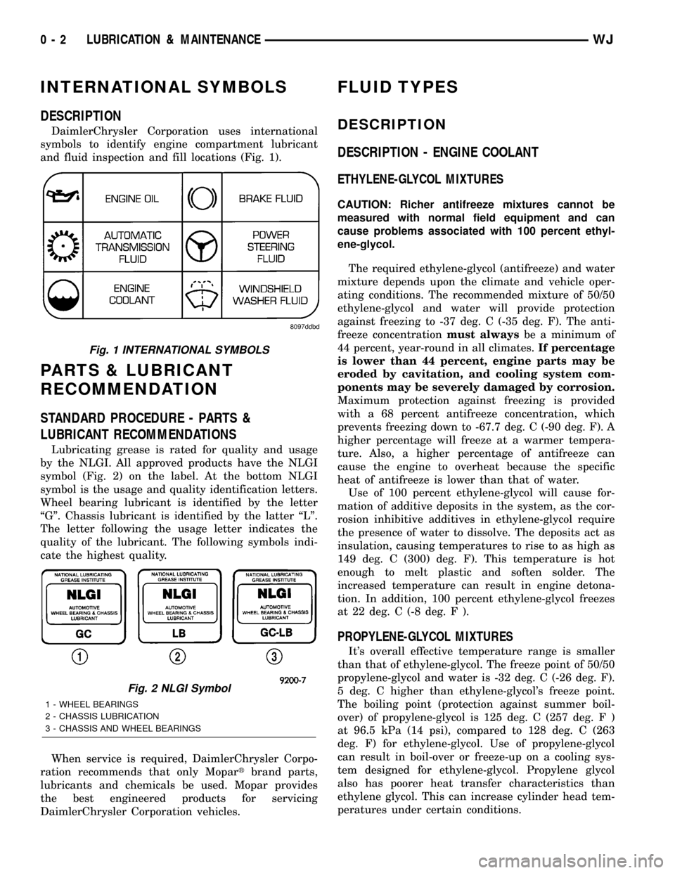
DaimlerChrysler Corporation uses international
symbols to identify engine compartment lubricant
and fluid inspection and fill locations (Fig. 1).
PARTS & LUBRICANT
RECOMMENDATION
STANDARD PROCEDURE - PARTS &
LUBRICANT RECOMMENDATIONS
Lubricating grease is rated for quality and usage
by the NLGI. All approved products have the NLGI
symbol (Fig. 2) on the label. At the bottom NLGI
symbol is the usage and quality identification letters.
Wheel bearing lubricant is identified by the letter
ªGº. Chassis lubricant is identified by the latter ªLº.
The letter following the usage letter indicates the
quality of the lubricant. The following symbols indi-
cate the highest quality.
When service is required, DaimlerChrysler Corpo-
ration recommends that only Mopartbrand parts,
lubricants and chemicals be used. Mopar provides
the best engineered products for servicing
DaimlerChrysler Corporation vehicles.
FLUID TYPES
DESCRIPTION
DESCRIPTION - ENGINE COOLANT
ETHYLENE-GLYCOL MIXTURES
CAUTION: Richer antifreeze mixtures cannot be
measured with normal field equipment and can
cause problems associated with 100 percent ethyl-
ene-glycol.
The required ethylene-glycol (antifreeze) and water
mixture depends upon the climate and vehicle oper-
ating conditions. The recommended mixture of 50/50
ethylene-glycol and water will provide protection
against freezing to -37 deg. C (-35 deg. F). The anti-
freeze concentrationmust alwaysbe a minimum of
44 percent, year-round in all climates.If percentage
is lower than 44 percent, engine parts may be
eroded by cavitation, and cooling system com-
ponents may be severely damaged by corrosion.
Maximum protection against freezing is provided
with a 68 percent antifreeze concentration, which
prevents freezing down to -67.7 deg. C (-90 deg. F). A
higher percentage will freeze at a warmer tempera-
ture. Also, a higher percentage of antifreeze can
cause the engine to overheat because the specific
heat of antifreeze is lower than that of water.
Use of 100 percent ethylene-glycol will cause for-
mation of additive deposits in the system, as the cor-
rosion inhibitive additives in ethylene-glycol require
the presence of water to dissolve. The deposits act as
insulation, causing temperatures to rise to as high as
149 deg. C (300) deg. F). This temperature is hot
enough to melt plastic and soften solder. The
increased temperature can result in engine detona-
tion. In addition, 100 percent ethylene-glycol freezes
at 22 deg. C (-8 deg. F ).
PROPYLENE-GLYCOL MIXTURES
It's overall effective temperature range is smaller
than that of ethylene-glycol. The freeze point of 50/50
propylene-glycol and water is -32 deg. C (-26 deg. F).
5 deg. C higher than ethylene-glycol's freeze point.
The boiling point (protection against summer boil-
over) of propylene-glycol is 125 deg. C (257 deg. F )
at 96.5 kPa (14 psi), compared to 128 deg. C (263
deg. F) for ethylene-glycol. Use of propylene-glycol
can result in boil-over or freeze-up on a cooling sys-
tem designed for ethylene-glycol. Propylene glycol
also has poorer heat transfer characteristics than
ethylene glycol. This can increase cylinder head tem-
peratures under certain conditions.
Fig. 1 INTERNATIONAL SYMBOLS
Fig. 2 NLGI Symbol
1 - WHEEL BEARINGS
2 - CHASSIS LUBRICATION
3 - CHASSIS AND WHEEL BEARINGS
0 - 2 LUBRICATION & MAINTENANCEWJ
Page 17 of 2199

DESCRIPTION - ENGINE OIL - DIESEL
ENGINES
Use only Diesel Engine Oil meeting standardMIL-
2104Cor API ClassificationCD or higherorCCML
D4, D5.
SAE VISCOSITY GRADE
CAUTION: Low viscosity oils must have the proper
API quality or the CCMC G5 designation.
To assure of properly formulated engine oils, it is
recommended that SAE Grade 10W-40 engine oils
that meet Chrysler material standard MS-6395, be
used. European Grade 10W-40 oils are also accept-
able.
Oils of the SAE 5W-40 or 8W-80 grade number are
preferred when minimum temperatures consistently
fall below -12ÉC.
OPERATION - AUTOMATIC TRANSMISSION
FLUID
The automatic transmission fluid is selected based
upon several qualities. The fluid must provide a high
level of protection for the internal components by
providing a lubricating film between adjacent metal
components. The fluid must also be thermally stable
so that it can maintain a consistent viscosity through
a large temperature range. If the viscosity stays con-
stant through the temperature range of operation,
transmission operation and shift feel will remain con-
sistent. Transmission fluid must also be a good con-
ductor of heat. The fluid must absorb heat from the
internal transmission components and transfer that
heat to the transmission case.
FLUID FILL/CHECK
LOCATIONS
INSPECTION - FLUID FILL/CHECK LOCATIONS
The fluid fill/check locations and lubrication points
are located in each applicable group.
MAINTENANCE SCHEDULES
DESCRIPTION
9Maintenance Schedule Information not included in
this section, is located in the appropriate Owner's
Manual.9
LIFT POINTS
STANDARD PROCEDURE - HOISTING AND
JACKING RECOMMENDATIONS
FLOOR JACK
When properly positioned, a floor jack can be used
to lift a WJ vehicle (Fig. 7). Support the vehicle in
the raised position with jack stands at the front and
rear ends of the frame rails.
CAUTION: Do not attempt to lift a vehicle with a
floor jack positioned under:
²An axle tube.
²Aluminum differential.
²A body side sill.
²A steering linkage component.
²A drive shaft.
²The engine or transmission oil pan.
²The fuel tank.
²A front suspension arm.
HOIST
A vehicle can be lifted with:
²A single-post, frame-contact hoist.
²A twin-post, chassis hoist.
²A ramp-type, drive-on hoist.
NOTE: When a frame-contact type hoist is used,
verify that the lifting pads are positioned properly
(Fig. 7).
WARNING: THE HOISTING AND JACK LIFTING
POINTS PROVIDED ARE FOR A COMPLETE VEHI-
CLE. WHEN A CHASSIS OR DRIVETRAIN COMPO-
NENT IS REMOVED FROM A VEHICLE, THE
CENTER OF GRAVITY IS ALTERED MAKING SOME
HOISTING CONDITIONS UNSTABLE. PROPERLY
SUPPORT OR SECURE VEHICLE TO HOISTING
DEVICE WHEN THESE CONDITIONS EXIST.
0 - 6 LUBRICATION & MAINTENANCEWJ
FLUID TYPES (Continued)
Page 66 of 2199
INSTALLATION
CAUTION: The weight of the vehicle must be sup-
ported by the springs before suspension arms and
track bar fasteners can be tightened. If springs are
not at their normal ride position, ride height and
handling could be affected.
(1) Install the springs and retainer clips. Tighten
the retainer bolts to 21 N´m (16 ft. lbs.).
(2) Support the axle on a lifting device and posi-
tion axle under the vehicle.
(3) Raise the axle and align it with the spring
pads.
(4) Position the upper and lower suspension arms
in the axle brackets. Loosely install bolts and nuts to
hold suspension arms to the axle brackets.
(5) Install vent hose to the axle shaft tube.
(6) Install track bar in the axle bracket and install
the bolt loosely.
(7) Install shock absorbers and tighten the bolts to
23 N´m (17 ft. lbs.).
(8) Install stabilizer bar links to the axle brackets
and tighten the nuts to 95 N´m (70 ft. lbs.).
(9) Install drag link and tie rod to the steering
knuckles.
(10) Install steering damper to the axle bracket
and tighten the nut to 75 N´m (55 ft. lbs.).
(11) Install the brake rotors (Refer to 5 - BRAKES/
HYDRAULIC/MECHANICAL/ROTORS - INSTALLA-
TION) and calipers.
(12) Connect the wheel speed sensor wiring har-
ness to the vehicle wiring harness.
(13) Align the previously made marks on the pro-
peller shaft and the yoke/pinion flange.
(14) Install propeller shaft to pinion flange bolts ,
if equipped.
(15) Install propeller shaft to yoke straps and
bolts, if equipped.
(16) Check and fill axle lubricant.
(17) Install the wheel and tire assemblies.
(18) Remove the lifting device from the axle and
lower the vehicle.
(19) Tighten the upper suspension arm nuts to 75
N´m (55 ft. lbs.). Tighten the lower suspension arm
nuts to 115 N´m (85 ft. lbs.).
(20) Tighten the track bar bolt at the axle bracket
to 100 N´m (74 ft. lbs.).
(21) Check the front wheel alignment.
ADJUSTMENTS
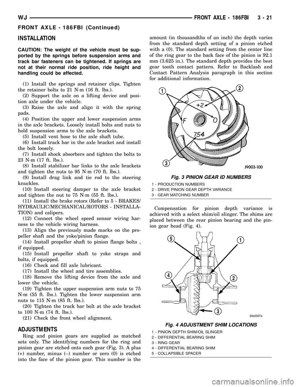
Ring and pinion gears are supplied as matched
sets only. The identifying numbers for the ring and
pinion gear are etched onto each gear (Fig. 3). A plus
(+) number, minus (±) number or zero (0) is etched
into the face of the pinion gear. This number is theamount (in thousandths of an inch) the depth varies
from the standard depth setting of a pinion etched
with a (0). The standard setting from the center line
of the ring gear to the back face of the pinion is 92.1
mm (3.625 in.). The standard depth provides the best
gear tooth contact pattern. Refer to Backlash and
Contact Pattern Analysis paragraph in this section
for additional information.
Compensation for pinion depth variance is
achieved with a select shim/oil slinger. The shims are
placed between the rear pinion bearing and the pin-
ion gear head (Fig. 4).
Fig. 3 PINION GEAR ID NUMBERS
1 - PRODUCTION NUMBERS
2 - DRIVE PINION GEAR DEPTH VARIANCE
3 - GEAR MATCHING NUMBER
Fig. 4 ADJUSTMENT SHIM LOCATIONS
1 - PINION DEPTH SHIM/OIL SLINGER
2 - DIFFERENTIAL BEARING SHIM
3 - RING GEAR
4 - DIFFERENTIAL BEARING SHIM
5 - COLLAPSIBLE SPACER
WJFRONT AXLE - 186FBI 3 - 21
FRONT AXLE - 186FBI (Continued)
Page 85 of 2199
²New Bearings: 1.7 to 3.4 N´m (15 to 30 in. lbs.).
(9) Install propeller shaft with reference marks
aligned.
(10) Install brake rotors and calipers.
(11) Add gear lubricant if necessary.
(12) Install wheel and tire assemblies.
(13) Lower vehicle.
DIFFERENTIAL
REMOVAL
(1) Raise and support the vehicle.
(2) Remove lubricant fill hole plug from the differ-
ential housing cover.
(3) Remove differential cover and drain lubricant.
(4) Clean the housing cavity with a flushing oil,
light engine oil or lint free cloth.Never use water,
steam, kerosene or gasoline for cleaning.
(5) Remove hub bearings and axle shafts.
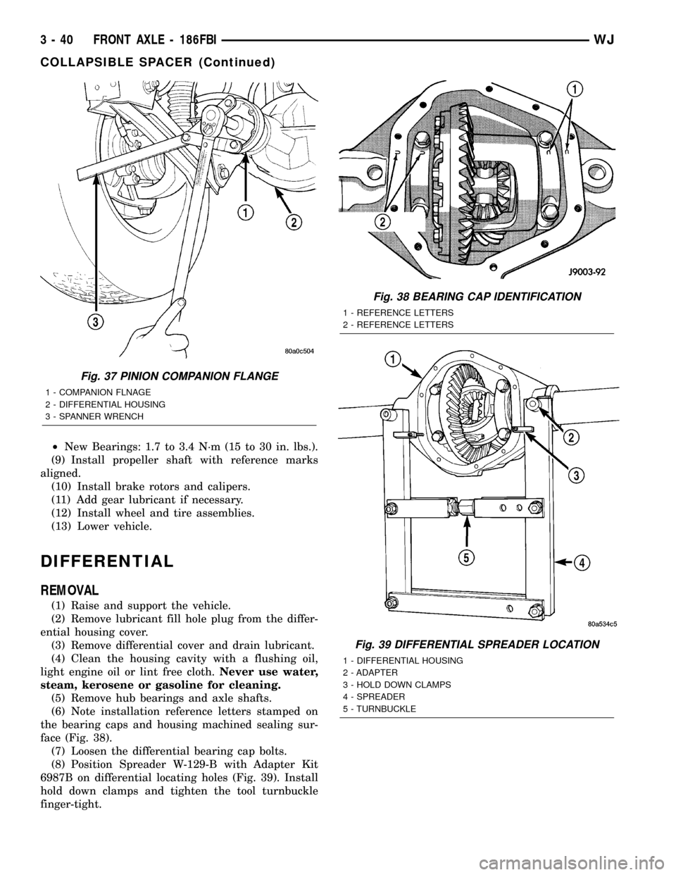
(6) Note installation reference letters stamped on
the bearing caps and housing machined sealing sur-
face (Fig. 38).
(7) Loosen the differential bearing cap bolts.
(8) Position Spreader W-129-B with Adapter Kit
6987B on differential locating holes (Fig. 39). Install
hold down clamps and tighten the tool turnbuckle
finger-tight.
Fig. 37 PINION COMPANION FLANGE
1 - COMPANION FLNAGE
2 - DIFFERENTIAL HOUSING
3 - SPANNER WRENCH
Fig. 38 BEARING CAP IDENTIFICATION
1 - REFERENCE LETTERS
2 - REFERENCE LETTERS
Fig. 39 DIFFERENTIAL SPREADER LOCATION
1 - DIFFERENTIAL HOUSING
2 - ADAPTER
3 - HOLD DOWN CLAMPS
4 - SPREADER
5 - TURNBUCKLE
3 - 40 FRONT AXLE - 186FBIWJ
COLLAPSIBLE SPACER (Continued)
Page 120 of 2199
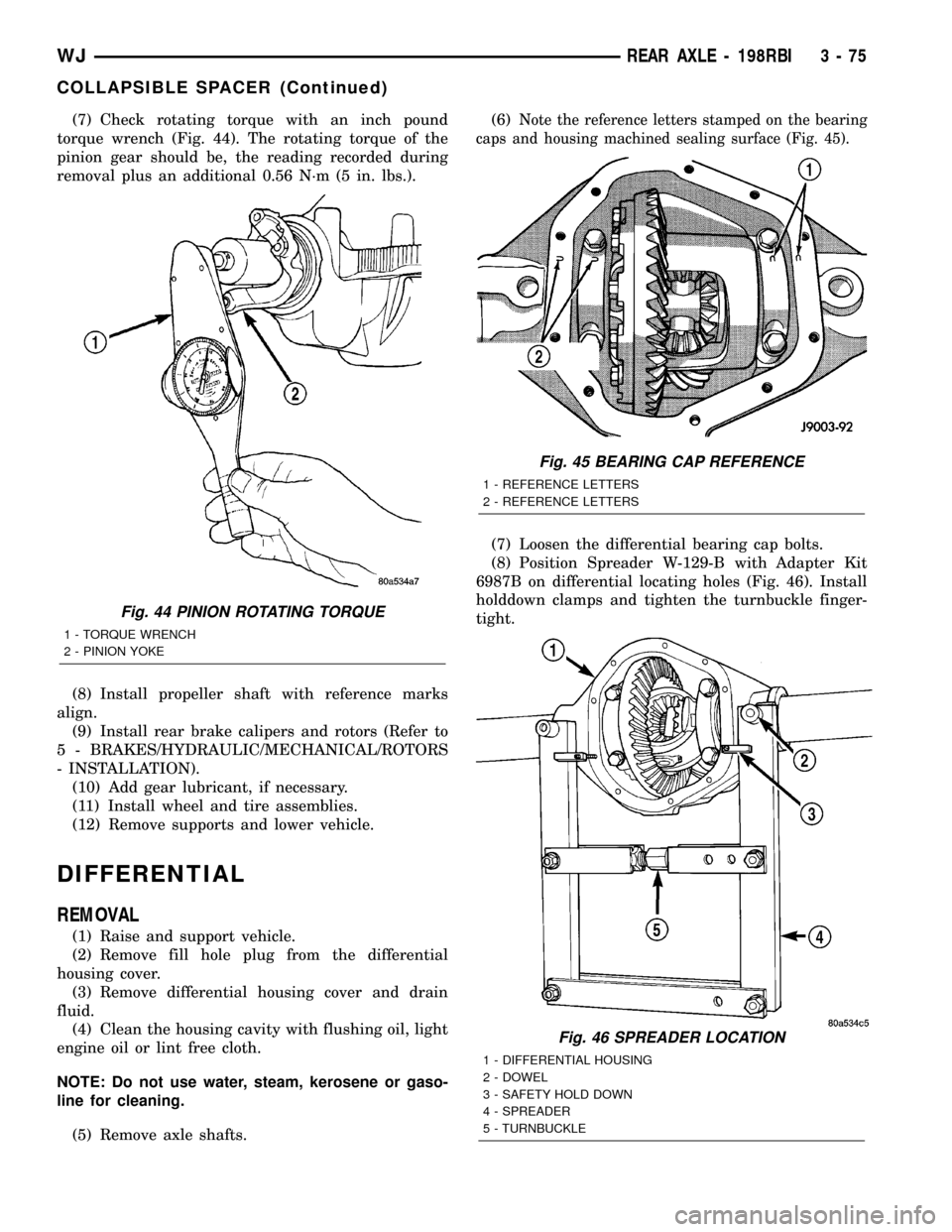
(7) Check rotating torque with an inch pound
torque wrench (Fig. 44). The rotating torque of the
pinion gear should be, the reading recorded during
removal plus an additional 0.56 N´m (5 in. lbs.).
(8) Install propeller shaft with reference marks
align.
(9) Install rear brake calipers and rotors (Refer to
5 - BRAKES/HYDRAULIC/MECHANICAL/ROTORS
- INSTALLATION).
(10) Add gear lubricant, if necessary.
(11) Install wheel and tire assemblies.
(12) Remove supports and lower vehicle.
DIFFERENTIAL
REMOVAL
(1) Raise and support vehicle.
(2) Remove fill hole plug from the differential
housing cover.
(3) Remove differential housing cover and drain
fluid.
(4) Clean the housing cavity with flushing oil, light
engine oil or lint free cloth.
NOTE: Do not use water, steam, kerosene or gaso-
line for cleaning.
(5) Remove axle shafts.(6)
Note the reference letters stamped on the bearing
caps and housing machined sealing surface (Fig. 45).
(7) Loosen the differential bearing cap bolts.
(8) Position Spreader W-129-B with Adapter Kit
6987B on differential locating holes (Fig. 46). Install
holddown clamps and tighten the turnbuckle finger-
tight.
Fig. 44 PINION ROTATING TORQUE
1 - TORQUE WRENCH
2 - PINION YOKE
Fig. 45 BEARING CAP REFERENCE
1 - REFERENCE LETTERS
2 - REFERENCE LETTERS
Fig. 46 SPREADER LOCATION
1 - DIFFERENTIAL HOUSING
2 - DOWEL
3 - SAFETY HOLD DOWN
4 - SPREADER
5 - TURNBUCKLE
WJREAR AXLE - 198RBI 3 - 75
COLLAPSIBLE SPACER (Continued)
Page 160 of 2199
NOTE: If more than 380 N´m (280 ft. lbs.) torque is
required to crush the collapsible spacer, the spacer
is defective and must be replaced.
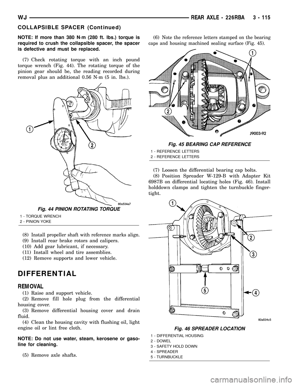
(7) Check rotating torque with an inch pound
torque wrench (Fig. 44). The rotating torque of the
pinion gear should be, the reading recorded during
removal plus an additional 0.56 N´m (5 in. lbs.).
(8)
Install propeller shaft with reference marks align.
(9) Install rear brake rotors and calipers.
(10) Add gear lubricant, if necessary.
(11) Install wheel and tire assemblies.
(12) Remove supports and lower vehicle.
DIFFERENTIAL
REMOVAL
(1) Raise and support vehicle.
(2) Remove fill hole plug from the differential
housing cover.
(3) Remove differential housing cover and drain
fluid.
(4) Clean the housing cavity with flushing oil, light
engine oil or lint free cloth.
NOTE: Do not use water, steam, kerosene or gaso-
line for cleaning.
(5) Remove axle shafts.(6)
Note the reference letters stamped on the bearing
caps and housing machined sealing surface (Fig. 45).
(7) Loosen the differential bearing cap bolts.
(8) Position Spreader W-129-B with Adapter Kit
6987B on differential locating holes (Fig. 46). Install
holddown clamps and tighten the turnbuckle finger-
tight.
Fig. 44 PINION ROTATING TORQUE
1 - TORQUE WRENCH
2 - PINION YOKE
Fig. 45 BEARING CAP REFERENCE
1 - REFERENCE LETTERS
2 - REFERENCE LETTERS
Fig. 46 SPREADER LOCATION
1 - DIFFERENTIAL HOUSING
2 - DOWEL
3 - SAFETY HOLD DOWN
4 - SPREADER
5 - TURNBUCKLE
WJREAR AXLE - 226RBA 3 - 115
COLLAPSIBLE SPACER (Continued)
Page 227 of 2199
²SLIGHT TAIL WIND AT IDLE
²SLOW TRAFFIC
²TRAFFIC JAMS
²HIGH SPEED
²STEEP GRADES
Driving techniques that avoid overheating are:
²Idle with A/C off when temperature gauge is at
end of normal range.
²Increase engine speed for more air flow is recom-
mended.(1) TRAILER TOWING:
Consult Trailer Towing section of owners manual.
Do not exceed limits.
(2) AIR CONDITIONING; ADD-ON OR AFTER
MARKET:
A maximum cooling package should have been
ordered with vehicle if add-on or after market A/C is
installed. If not, maximum cooling system compo-
nents should be installed for model involved per
manufacturer's specifications.
(3) RECENT SERVICE OR ACCIDENT REPAIR:
Determine if any recent service has been per-
formed on vehicle that may effect cooling system.
This may be:
²Engine adjustments (incorrect timing)
²Slipping engine accessory drive belt(s)
²Brakes (possibly dragging)
²Changed parts. Incorrect water pump, or pump
rotating in wrong direction due to belt not correctly
routed
²Reconditioned radiator or cooling system refill-
ing (possibly under filled or air trapped in system).
NOTE: If investigation reveals none of the previous
items as a cause for an engine overheating com-
plaint, refer to following Cooling System Diagnosis
charts.
These charts are to be used as a quick-reference
only. Refer to the group text for information.
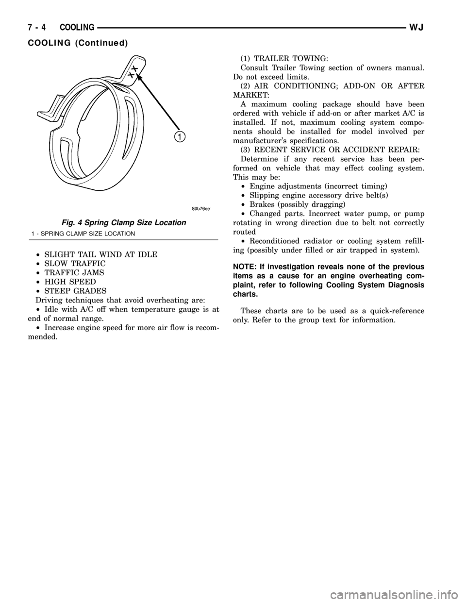
Fig. 4 Spring Clamp Size Location
1 - SPRING CLAMP SIZE LOCATION
7 - 4 COOLINGWJ
COOLING (Continued)
Page 262 of 2199
(5) Install electrical connector to coolant tempera-
ture sensor.
(6) Be sure that the radiator draincock is tightly
closed. Fill the cooling system to the correct levelwith the required coolant mixture (Refer to 7 -
COOLING - STANDARD PROCEDURE).
(7) Start and warm the engine. Check for leaks.
INSTALLATIONÐ4.7L ENGINE
(1) Clean mating areas of timing chain cover and
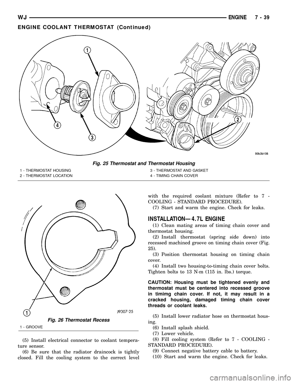
thermostat housing.
(2) Install thermostat (spring side down) into
recessed machined groove on timing chain cover (Fig.
25).
(3) Position thermostat housing on timing chain
cover.
(4) Install two housing-to-timing chain cover bolts.
Tighten bolts to 13 N´m (115 in. lbs.) torque.
CAUTION: Housing must be tightened evenly and
thermostat must be centered into recessed groove
in timimg chain cover. If not, it may result in a
cracked housing, damaged timing chain cover
threads or coolant leaks.
(5) Install lower radiator hose on thermostat hous-
ing.
(6) Install splash shield.
(7) Lower vehicle.
(8) Fill cooling system (Refer to 7 - COOLING -
STANDARD PROCEDURE).
(9) Connect negative battery cable to battery.
(10) Start and warm the engine. Check for leaks.
Fig. 25 Thermostat and Thermostat Housing
1 - THERMOSTAT HOUSING
2 - THERMOSTAT LOCATION3 - THERMOSTAT AND GASKET
4 - TIMING CHAIN COVER
Fig. 26 Thermostat Recess
1 - GROOVE
WJENGINE 7 - 39
ENGINE COOLANT THERMOSTAT (Continued)
Page 270 of 2199
INSPECTION
The radiator cooling fins should be checked for
damage or deterioration. Inspect cooling fins to make
sure they are not bent or crushed, these areas result
in reduced heat exchange causing the cooling system
to operate at higher temperatures. Inspect the plastic
end tanks for cracks, damage or leaks.
Inspect the radiator neck for damage or distortion.
INSTALLATION
CAUTION: Before installing the radiator or A/C con-
denser, be sure the radiator-to-body and radiator-to-
A/C condenser rubber air seals (Fig. 39) are
properly fastened to their original positions. These
are used at the top, bottom and sides of the radia-
tor and A/C condenser. To prevent overheating,
these seals must be installed to their original posi-
tions.
(1) Equipped with air conditioning: Gently lower
the radiator into the vehicle. Guide the two radiator
alignment dowels through the holes in the rubber air
seals first and then through the A/C support brackets
(Fig. 40). Continue to guide the alignment dowels
into the rubber grommets located in lower radiator
crossmember. The holes in the L-shaped brackets
(located on bottom of A/C condenser) must be posi-
tioned between bottom of rubber air seals and top of
rubber grommets.
(2) Connect the radiator upper and lower hoses
and hose clamps to radiator (Fig. 41).
CAUTION: The tangs on the hose clamps must be
positioned straight down.
(3) Install coolant reserve/overflow tank hose at
radiator (Fig. 41).
(4) Connect both transmission cooler lines at the
radiator (Fig. 41).
(5) Install both radiator mounting bolts (Fig. 41).
(6) Install air inlet duct at grill.
(7) Attach electric fan harness to shroud, then con-
nect harness to connector (Fig. 41).
(8) Install the grill (Refer to 23 - BODY/EXTERI-
OR/GRILLE - INSTALLATION).
(9) Install the fan/viscous fan drive assembly to
the water pump.
(10) Rotate the fan blades (by hand) and check for
interference at fan shroud.
(11) Be sure of at least 25 mm (1.0 inch) between
tips of fan blades and fan shroud.
(12) Fill cooling system (Refer to 7 - COOLING -
STANDARD PROCEDURE).
(13) Connect battery cable at battery.
(14) Start and warm engine. Check for leaks.
RADIATOR FAN MOTOR
DIAGNOSIS AND TESTINGÐELECTRIC
COOLING FAN
The powertrain control module (PCM) will enter a
diagnostic trouble code (DTC) in memory if it detects
a problem in the auxiliary cooling fan relay or circuit.
(Refer to 25 - EMISSIONS CONTROL - DESCRIP-
TION).
If the electric cooling fan is inoperative, check the
15A fuse in the junction block and the 40A fuse in
the Power Distribution Center (PDC) with a 12 volt
test lamp or DVOM. Refer to the inside of the PDC
cover for the exact location of the fuse. If fuses are
okay, refer to ELECTRICAL for cooling fan and relay
circuit schematic.
WATER PUMP - 4.7L
DESCRIPTION
DESCRIPTIONÐWATER PUMP
A centrifugal water pump circulates coolant
through the water jackets, passages, intake manifold,
radiator core, cooling system hoses and heater core.
The pump is driven from the engine crankshaft by a
single serpentine drive belt.
The water pump impeller is pressed onto the rear
of a shaft that rotates in bearings pressed into the
housing. The housing has two small holes to allow
seepage to escape. The water pump seals are lubri-
cated by the antifreeze in the coolant mixture. No
additional lubrication is necessary.
Both heater hoses are connected to fittings on the
timing chain front cover. The water pump is also
mounted directly to the timing chain cover and is
equipped with a non serviceable integral pulley (Fig.
42).
DESCRIPTIONÐWATER PUMP BYPASS
The 4.7L engine uses an internal water/coolant
bypass system. The design uses galleries in the tim-
ing chain cover to circulate coolant during engine
warm-up preventing the coolant from flowing
through the radiator. The thermostat uses a stub
shaft located at the rear of the thermostat (Fig. 43)
to control flow through the bypass gallery.
OPERATION
OPERATIONÐWATER PUMP
A centrifugal water pump circulates coolant
through the water jackets, passages, intake manifold,
WJENGINE 7 - 47
RADIATOR - 4.0L (Continued)