Power steering JEEP GRAND CHEROKEE 2003 WJ / 2.G Workshop Manual
[x] Cancel search | Manufacturer: JEEP, Model Year: 2003, Model line: GRAND CHEROKEE, Model: JEEP GRAND CHEROKEE 2003 WJ / 2.GPages: 2199, PDF Size: 76.01 MB
Page 1 of 2199
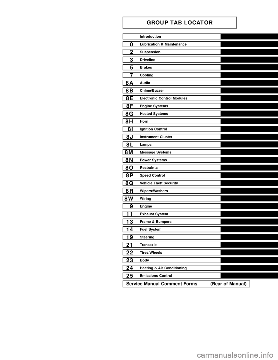
GROUP TAB LOCATOR
Introduction
0Lubrication & Maintenance
2Suspension
3Driveline
5Brakes
7Cooling
8AAudio
8BChime/Buzzer
8EElectronic Control Modules
8FEngine Systems
8GHeated Systems
8HHorn
8IIgnition Control
8JInstrument Cluster
8LLamps
8MMessage Systems
8NPower Systems
8ORestraints
8PSpeed Control
8QVehicle Theft Security
8RWipers/Washers
8WWiring
9Engine
11Exhaust System
13Frame & Bumpers
14Fuel System
19Steering
21Transaxle
22Tires/Wheels
23Body
24Heating & Air Conditioning
25Emissions Control
Service Manual Comment Forms (Rear of Manual)
Page 22 of 2199
SUSPENSION
TABLE OF CONTENTS
page page
SUSPENSION
DIAGNOSIS AND TESTING - SUSPENSION
AND STEERING SYSTEM................1WHEEL ALIGNMENT......................3
FRONT.................................6
REAR.................................17
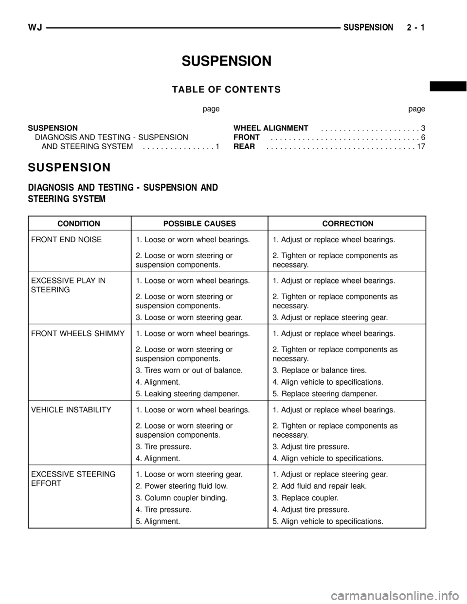
SUSPENSION
DIAGNOSIS AND TESTING - SUSPENSION AND
STEERING SYSTEM
CONDITION POSSIBLE CAUSES CORRECTION
FRONT END NOISE 1. Loose or worn wheel bearings. 1. Adjust or replace wheel bearings.
2. Loose or worn steering or
suspension components.2. Tighten or replace components as
necessary.
EXCESSIVE PLAY IN
STEERING1. Loose or worn wheel bearings. 1. Adjust or replace wheel bearings.
2. Loose or worn steering or
suspension components.2. Tighten or replace components as
necessary.
3. Loose or worn steering gear. 3. Adjust or replace steering gear.
FRONT WHEELS SHIMMY 1. Loose or worn wheel bearings. 1. Adjust or replace wheel bearings.
2. Loose or worn steering or
suspension components.2. Tighten or replace components as
necessary.
3. Tires worn or out of balance. 3. Replace or balance tires.
4. Alignment. 4. Align vehicle to specifications.
5. Leaking steering dampener. 5. Replace steering dampener.
VEHICLE INSTABILITY 1. Loose or worn wheel bearings. 1. Adjust or replace wheel bearings.
2. Loose or worn steering or
suspension components.2. Tighten or replace components as
necessary.
3. Tire pressure. 3. Adjust tire pressure.
4. Alignment. 4. Align vehicle to specifications.
EXCESSIVE STEERING
EFFORT1. Loose or worn steering gear. 1. Adjust or replace steering gear.
2. Power steering fluid low. 2. Add fluid and repair leak.
3. Column coupler binding. 3. Replace coupler.
4. Tire pressure. 4. Adjust tire pressure.
5. Alignment. 5. Align vehicle to specifications.
WJSUSPENSION 2 - 1
Page 178 of 2199

(2) If complaint was based on noise when braking,
check suspension components. Jounce front and rear
of vehicle and listen for noise that might be caused
by loose, worn or damaged suspension or steering
components.
(3) Inspect brake fluid level and condition. Note
that the brake reservoir fluid level will decrease in
proportion to normal lining wear.Also note that
brake fluid tends to darken over time. This is
normal and should not be mistaken for contam-
ination.
(a) If fluid level is abnormally low, look for evi-
dence of leaks at calipers, brake lines, master cyl-
inder, and HCU.
(b) If fluid appears contaminated, drain out a
sample to examine. System will have to be flushed
if fluid is separated into layers, or contains a sub-
stance other than brake fluid. The system seals,
cups, hoses, master cylinder, and HCU will also
have to be replaced after flushing. Use clean brake
fluid to flush the system.
(4) Check parking brake operation. Verify free
movement and full release of cables and lever. Also
note if vehicle was being operated with parking
brake partially applied.
(5) Check brake pedal operation. Verify that pedal
does not bind and has adequate free play. If pedal
lacks free play, check pedal and power booster for
being loose or for bind condition. Do not road test
until condition is corrected.
(6) Check booster vacuum check valve and hose.
(7) If components checked appear OK, road test
the vehicle.
ROAD TESTING
(1) If complaint involved low brake pedal, pump
pedal and note if it comes back up to normal height.
(2) Check brake pedal response with transmission
in neutral and engine running. Pedal should remain
firm under constant foot pressure.
(3) During road test, make normal and firm brake
stops in 25-40 mph range. Note faulty brake opera-
tion such as low pedal, hard pedal, fade, pedal pulsa-
tion, pull, grab, drag, noise, etc.
(4) Attempt to stop the vehicle with the parking
brake only (do not exceed 25 mph) and note grab,
drag, noise, etc.
PEDAL FALLS AWAY
A brake pedal that falls away under steady foot
pressure is generally the result of a system leak. The
leak point could be at a brake line, fitting, hose, or
caliper. If leakage is severe, fluid will be evident at
or around the leaking component.Internal leakage (seal by-pass) in the master cylin-
der caused by worn or damaged piston cups, may
also be the problem cause.
An internal leak in the ABS system may also be
the problem with no visual fluid leak.
LOW PEDAL
If a low pedal is experienced, pump the pedal sev-
eral times. If the pedal comes back up, the most
likely causes are worn linings, rotors, or calipers are
not sliding on the slide pins. The proper course of
action is to inspect and replace all worn component.
SPONGY PEDAL
A spongy pedal is most often caused by air in the
system. However substandard brake hoses can cause
a spongy pedal. The proper course of action is to
bleed the system, and replace substandard quality
brake hoses if suspected.
HARD PEDAL OR HIGH PEDAL EFFORT
A hard pedal or high pedal effort may be due to
lining that is water soaked, contaminated, glazed, or
badly worn. The power booster, check valve, check
valve seal/grommet or vacuum leak could also cause
a hard pedal or high pedal effort.
PEDAL PULSATION
Pedal pulsation is caused by components that are
loose, or beyond tolerance limits.
The primary cause of pulsation are disc brake
rotors with excessive lateral runout or thickness vari-
ation. Other causes are loose wheel bearings or cali-
pers and worn, damaged tires.
NOTE: Some pedal pulsation may be felt during
ABS activation.
BRAKE DRAG
Brake drag occurs when the lining is in constant
contact with the rotor or drum. Drag can occur at one
wheel, all wheels, fronts only, or rears only.
Drag is a product of incomplete brake release.
Drag can be minor or severe enough to overheat the
linings, rotors and park brake drums.
Minor drag will usually cause slight surface charring
of the lining. It can also generate hard spots in rotors
and park brake drums from the overheat-cool down pro-
cess. In most cases, the rotors, wheels and tires are
quite warm to the touch after the vehicle is stopped.
Severe drag can char the brake lining all the way
through. It can also distort and score rotors to the
point of replacement. The wheels, tires and brake
components will be extremely hot. In severe cases,
the lining may generate smoke as it chars from over-
heating.
WJBRAKES - BASE 5 - 3
BRAKES - BASE (Continued)
Page 198 of 2199

rates into layers, there is mineral oil or other fluid
contamination of the brake fluid.
If brake fluid is contaminated, drain and thor-
oughly flush system. Replace master cylinder with
reservoir, caliper seals, HCU and all hydraulic fluid
hoses.
SPECIFICATIONS
BRAKE FLUID
The brake fluid used in this vehicle must conform
to DOT 3 specifications and SAE J1703 standards.
No other type of brake fluid is recommended or
approved for usage in the vehicle brake system. Use
only Mopar brake fluid or an equivalent from a
tightly sealed container.
CAUTION: Never use reclaimed brake fluid or fluid
from an container which has been left open. An
open container of brake fluid will absorb moisture
from the air and contaminate the fluid.
CAUTION: Never use any type of a petroleum-based
fluid in the brake hydraulic system. Use of such
type fluids will result in seal damage of the vehicle
brake hydraulic system causing a failure of the
vehicle brake system. Petroleum based fluids would
be items such as engine oil, transmission fluid,
power steering fluid, etc.
FLUID RESERVOIR
REMOVAL
(1) Remove reservoir cap and remove fluid with a
cleansuction gun.
(2) Remove the wire connector from the brake fluid
level sensor.
(3) Insert the tool (Fig. 47) provided with the res-
ervoir to release the reservoir retaining tabs.
(4) Pull the reservoir straight up out of the cylin-
der.
(5) Remove and discard grommets from the cylin-
der body.
INSTALLATION
(1) Lubricate new grommets with clean brake
fluid. Install new grommets into the cylinder body.
CAUTION: Do not use tools to install the grommets.
Tools may cut, or tear the grommets. Install the
grommets using finger pressure only.(2) Start reservoir in grommets then press the res-
ervoir straight down to seat the reservoir into the
cylinder grommets.
CAUTION: Do not rock the reservoir during installa-
tion.
(3) Verify retaining tabs are seated.
(4) Install the wire connector to the brake fluid
level sensor.
(5) Fill master cylinder.
MASTER CYLINDER
DESCRIPTION
The master cylinder body is made of aluminum
and contains a primary and secondary piston assem-
bly. The cylinder body including the piston assem-
blies are not serviceable. If diagnosis indicates an
internal problem with the cylinder body, it must be
replaced as an assembly. The master cylinder has a
removable reservoir and fluid level indicator. The res-
ervoir, reservoir grommets, reservoir cap and fluid
level switch are the only replaceable parts on the
master cylinder.
Fig. 47 Release Tool
1 - RESERVOIR
2 - RELEASE TOOL
3 - RETAINING TABS
WJBRAKES - BASE 5 - 23
FLUID (Continued)
Page 201 of 2199

tions also allows the driver to set steering wheel tilt
and seat position to the most comfortable position.
The position of the brake and accelerator pedals can
be adjusted without compromising safety or comfort
in actuating the pedals. Repositioning the pedals
does not change the effort required for actuation.
Change of pedal position is accomplished by means
of a motor driven screw. Operating the adjustable
pedal switch activates the pedal drive motor. The
pedal drive motor turns a screw that changes the
position of the brake and accelerator pedals. The
pedal can be moved rearward (closer to the driver) or
forward (away from driver). The brake pedal is
moved on its drive screw to a position where the
driver feels most comfortable (Fig. 52).
The accelerator pedal is moved at the same time
and the same distance as the brake pedal. The accel-
erator pedal adjustment screw is turned by a flexible
shaft slaved off the brake adjustment screw.
Neither the pedal drive motor nor drive mecha-
nism are subject to the mechanical stress of brake or
accelerator application.
²SYSTEM FEATURES:
²Range of Adjustment: The pedals may be
adjusted up to 3 in. (75 mm)
²Pedal Adjustment Speed: 0.5 in./sec (12.5
mm/sec)
²Pedal Adjustment Inhibitors: Pedal adjust-
ment is inhibited when the vehicle is in reverse or
when cruise control is activated.
²Memory: An optional memory feature is avail-
able. This allows storing of one or two preferred
pedal positions in the Adjustable Pedal Module
(APM). A preferred position can be stored and
recalled using the door-mounted switches. A stored
pedal position can be recalled (but not stored)
using the Remote Keyless Entry (RKE).
²
Adjustable Pedal Feedback Message: The Elec-
tronic Vehicle Information Center (EVIC) will display
a message when the APS is disabled. ie:9Adjustable
Pedal Disabled - Cruise Control Engaged9or9Adjust-
able Pedal Disabled - Vehicle in Reverse9.
²Damage Prevention: Foot pressure or debris
can stall pedal adjustment. In order to avoid dam-
age to system components during pedal adjust-
ment, the APM will monitor pedal position sensor
voltage. If the APM does not detect expected volt-
age change within 1.5 seconds, it will cut power to
the adjustable pedal motor.
OPERATION
The brake pedal is attached to the booster push
rod. When the pedal is depressed, the primary
booster push rod is depressed which moves the
booster secondary rod. The booster secondary rod
depresses the master cylinder piston.
REMOVAL
REMOVAL - NON-ADJUSTABLE PEDAL
(1) Remove retainer clip that holds booster to
pedal pin (Fig. 53).
Fig. 52 ADJUSTABLE PEDALS ASSEMBLY
1 - HARNESS
2 - ADJUSTABLE PEDAL BRACKET
3 - CABLE
4 - ACCELERATOR PEDAL
5 - BRAKE PEDAL
6 - ADJUSTABLE PEDAL MOTOR
7 - BRAKE LIGHT SWITCH
8 - ADJUSTABLE PEDALS MODULE
Fig. 53 Push Rod Retainer Clip
1 - RETAINER CLIP
2 - PUSH ROD
3 - PEDAL PIN
5 - 26 BRAKES - BASEWJ
PEDAL (Continued)
Page 224 of 2199

COOLING
TABLE OF CONTENTS
page page
COOLING
DESCRIPTION
DESCRIPTION - COOLING SYSTEM 4.7L
ENGINE..............................1
DESCRIPTION - COOLING SYSTEM
ROUTING 4.7L ENGINE..................1
DESCRIPTIONÐCOOLING SYSTEM 4.0L
ENGINE..............................1
DESCRIPTIONÐCOOLING SYSTEM
ROUTING 4.0L ENGINE..................1
DESCRIPTIONÐHOSE CLAMPS...........1
OPERATION
OPERATIONÐCOOLING SYSTEM.........2
OPERATIONÐHOSE CLAMPS............2
DIAGNOSIS AND TESTING
DIAGNOSIS AND TESTINGÐON-BOARD
DIAGNOSTICS (OBD)...................3
DIAGNOSIS AND TESTINGÐPRELIMINARY
CHECKS.............................3
DIAGNOSIS AND TESTING - COOLING
SYSTEM DIAGNOSIS CHART.............5
DIAGNOSIS AND TESTING - COOLING
SYSTEM LEAKS......................10DIAGNOSIS AND TESTING - COOLING
SYSTEM DEAERATION.................12
STANDARD PROCEDURE
STANDARD PROCEDUREÐDRAINING
COOLING SYSTEM 4.7L ENGINE.........12
STANDARD PROCEDURE - REFILLING
COOLING SYSTEM 4.7L ENGINE.........12
STANDARD PROCEDURE - DRAINING
COOLING SYSTEM - 4.0L ENGINE........13
STANDARD PROCEDURE - REFILLING
COOLING SYSTEM - 4.0L ENGINE........13
STANDARD PROCEDURE - ADDING
ADDITIONAL COOLANT.................13
STANDARD PROCEDURE - COOLING
SYSTEM - REVERSE FLUSHING..........14
SPECIFICATIONS
TORQUE............................14
SPECIAL TOOLS
COOLING...........................15
ACCESSORY DRIVE......................16
ENGINE...............................24
TRANSMISSION.........................55
COOLING
DESCRIPTION
DESCRIPTION - COOLING SYSTEM 4.7L
ENGINE
The cooling system consists of the following items:
²Hydraulic cooling fan and fan drive assembly
²Radiator
²Power steering oil cooler
²Radiator pressure cap
²Thermostat
²Coolant reserve/overflow system
²Transmission oil cooler (if equipped with an
automatic transmission)
²Coolant
²Water pump
²Hoses and hose clamps
DESCRIPTION - COOLING SYSTEM ROUTING
4.7L ENGINE
For cooling system routing refer to (Fig. 1).
DESCRIPTIONÐCOOLING SYSTEM 4.0L
ENGINE
The cooling system consists of:
²A radiator
²Mechanical Cooling Fan
²Thermal viscous fan drive-Low disengaged
²Fan shroud (Fig. 2)
²Radiator pressure cap
²Thermostat
²Coolant reserve/overflow system
²Transmission oil cooler (if equipped with an
automatic transmission)
²Coolant
²Water pump
²Hoses and hose clamps
²Accessory drive belt
DESCRIPTIONÐCOOLING SYSTEM ROUTING
4.0L ENGINE
For cooling system routing refer to (Fig. 3).
DESCRIPTIONÐHOSE CLAMPS
The cooling system utilizes both worm drive and
spring type hose clamps. If a spring type clamp
WJCOOLING 7 - 1
Page 230 of 2199
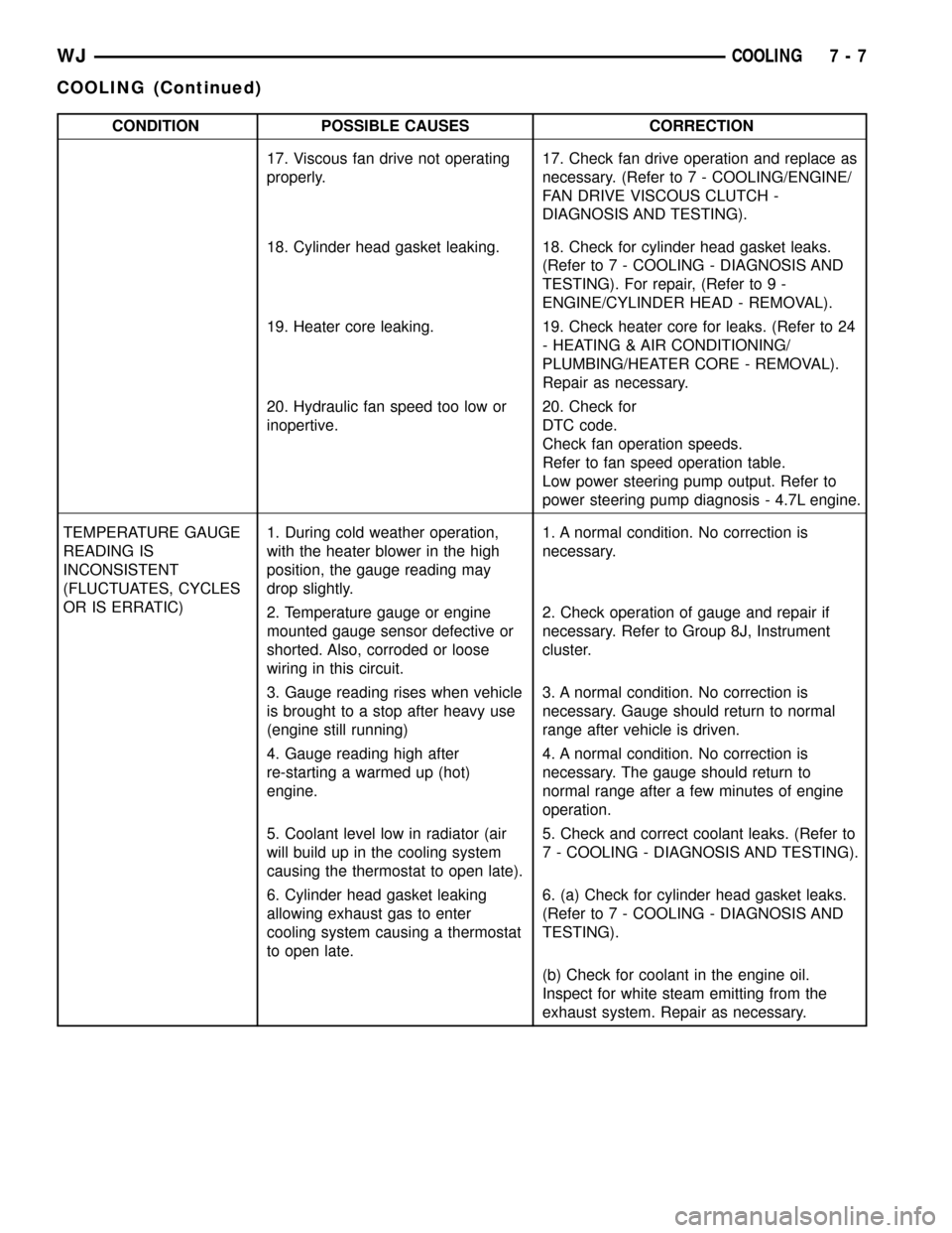
CONDITION POSSIBLE CAUSES CORRECTION
17. Viscous fan drive not operating
properly.17. Check fan drive operation and replace as
necessary. (Refer to 7 - COOLING/ENGINE/
FAN DRIVE VISCOUS CLUTCH -
DIAGNOSIS AND TESTING).
18. Cylinder head gasket leaking. 18. Check for cylinder head gasket leaks.
(Refer to 7 - COOLING - DIAGNOSIS AND
TESTING). For repair, (Refer to 9 -
ENGINE/CYLINDER HEAD - REMOVAL).
19. Heater core leaking. 19. Check heater core for leaks. (Refer to 24
- HEATING & AIR CONDITIONING/
PLUMBING/HEATER CORE - REMOVAL).
Repair as necessary.
20. Hydraulic fan speed too low or
inopertive.20. Check for
DTC code.
Check fan operation speeds.
Refer to fan speed operation table.
Low power steering pump output. Refer to
power steering pump diagnosis - 4.7L engine.
TEMPERATURE GAUGE
READING IS
INCONSISTENT
(FLUCTUATES, CYCLES
OR IS ERRATIC)1. During cold weather operation,
with the heater blower in the high
position, the gauge reading may
drop slightly.1. A normal condition. No correction is
necessary.
2. Temperature gauge or engine
mounted gauge sensor defective or
shorted. Also, corroded or loose
wiring in this circuit.2. Check operation of gauge and repair if
necessary. Refer to Group 8J, Instrument
cluster.
3. Gauge reading rises when vehicle
is brought to a stop after heavy use
(engine still running)3. A normal condition. No correction is
necessary. Gauge should return to normal
range after vehicle is driven.
4. Gauge reading high after
re-starting a warmed up (hot)
engine.4. A normal condition. No correction is
necessary. The gauge should return to
normal range after a few minutes of engine
operation.
5. Coolant level low in radiator (air
will build up in the cooling system
causing the thermostat to open late).5. Check and correct coolant leaks. (Refer to
7 - COOLING - DIAGNOSIS AND TESTING).
6. Cylinder head gasket leaking
allowing exhaust gas to enter
cooling system causing a thermostat
to open late.6. (a) Check for cylinder head gasket leaks.
(Refer to 7 - COOLING - DIAGNOSIS AND
TESTING).
(b) Check for coolant in the engine oil.
Inspect for white steam emitting from the
exhaust system. Repair as necessary.
WJCOOLING 7 - 7
COOLING (Continued)
Page 242 of 2199
CONDITION POSSIBLE CAUSES CORRECTION
BELT BROKEN (NOTE: IDENTIFY
AND CORRECT PROBLEM
BEFORE NEW BELT IS
INSTALLED)1. Excessive tension. 1. Replace belt and automatic belt
tensioner.
2. Incorrect belt. 2. Replace belt.
3. Tensile member damaged during
belt installation.3. Replace belt.
4. Severe misalignment. 4. Check and replace.
5. Bracket, pulley, or bearing failure. 5. Replace defective component
and belt.
NOISE (OBJECTIONABLE
SQUEAL, SQUEAK, OR RUMBLE
IS HEARD OR FELT WHILE
DRIVE BELT IS IN OPERATION)1. Belt slippage. 1. Replace belt or automatic belt
tensioner.
2. Bearing noise. 2. Locate and repair.
3. Belt misalignment. 3. Replace belt.
4. Belt-to-pulley mismatch. 4. Install correct belt.
REMOVALÐ4.0L ENGINE
NOTE: The belt routing schematics are published
from the latest information available at the time of
publication. If anything differs between these sche-
matics and the Belt Routing Label, use the sche-
matics on Belt Routing Label. This label is located
in the engine compartment.
CAUTION: DO NOT LET TENSIONER ARM SNAP
BACK TO THE FREEARM POSITION, SEVERE DAM-
AGE MAY OCCUR TO THE TENSIONER.
Belt tension is not adjustable. Belt adjustment is
maintained by an automatic ( spring load ) belt ten-
sioner.
(1) Disconnect negative battery cable from battery.
(2) Rotate belt tensioner until it contacts its stop.
Remove belt, then slowly rotate the tensioner into
the freearm position. (Fig. 4).
INSTALLATIONÐ4.0L ENGINE
NOTE: The belt routing schematics are published
from the latest information available at the time of
publication. If anything differs between these sche-
matics and the Belt Routing Label, use the sche-
matics on Belt Routing Label. This label is located
in the engine compartment.
Belt tension is not adjustable. Belt adjustment is
maintained by an automatic ( spring load ) belt ten-
sioner.
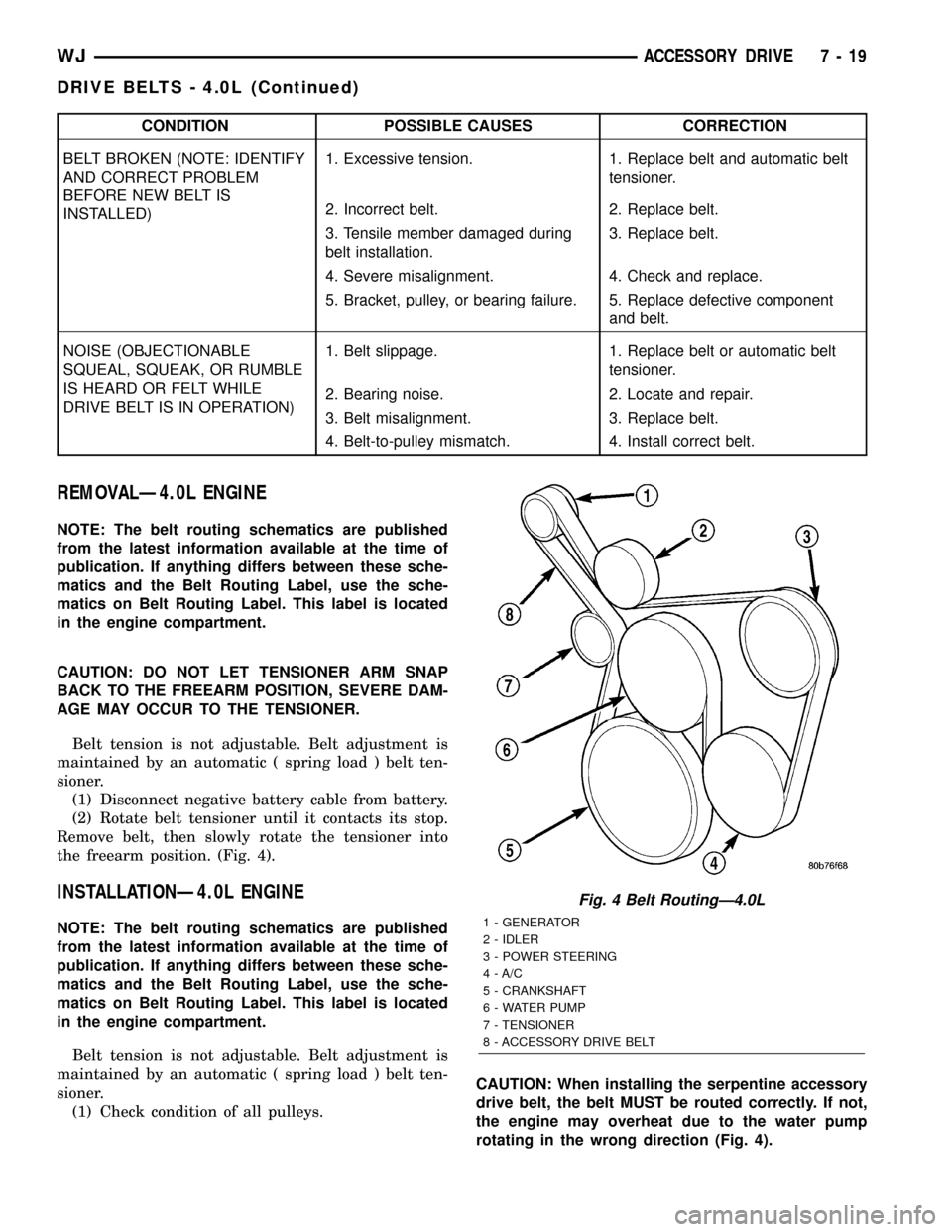
(1) Check condition of all pulleys.CAUTION: When installing the serpentine accessory
drive belt, the belt MUST be routed correctly. If not,
the engine may overheat due to the water pump
rotating in the wrong direction (Fig. 4).
Fig. 4 Belt RoutingÐ4.0L
1 - GENERATOR
2 - IDLER
3 - POWER STEERING
4 - A/C
5 - CRANKSHAFT
6 - WATER PUMP
7 - TENSIONER
8 - ACCESSORY DRIVE BELT
WJACCESSORY DRIVE 7 - 19
DRIVE BELTS - 4.0L (Continued)
Page 245 of 2199
CONDITION POSSIBLE CAUSES CORRECTION
BELT BROKEN (NOTE: IDENTIFY
AND CORRECT PROBLEM
BEFORE NEW BELT IS
INSTALLED)1. Excessive tension. 1. Replace belt and automatic belt
tensioner.
2. Incorrect belt. 2. Replace belt.
3. Tensile member damaged during
belt installation.3. Replace belt.
4. Severe misalignment. 4. Check and replace.
5. Bracket, pulley, or bearing failure. 5. Replace defective component
and belt.
NOISE (OBJECTIONABLE
SQUEAL, SQUEAK, OR RUMBLE
IS HEARD OR FELT WHILE
DRIVE BELT IS IN OPERATION)1. Belt slippage. 1. Replace belt or automatic belt
tensioner.
2. Bearing noise. 2. Locate and repair.
3. Belt misalignment. 3. Replace belt.
4. Belt-to-pulley mismatch. 4. Install correct belt.
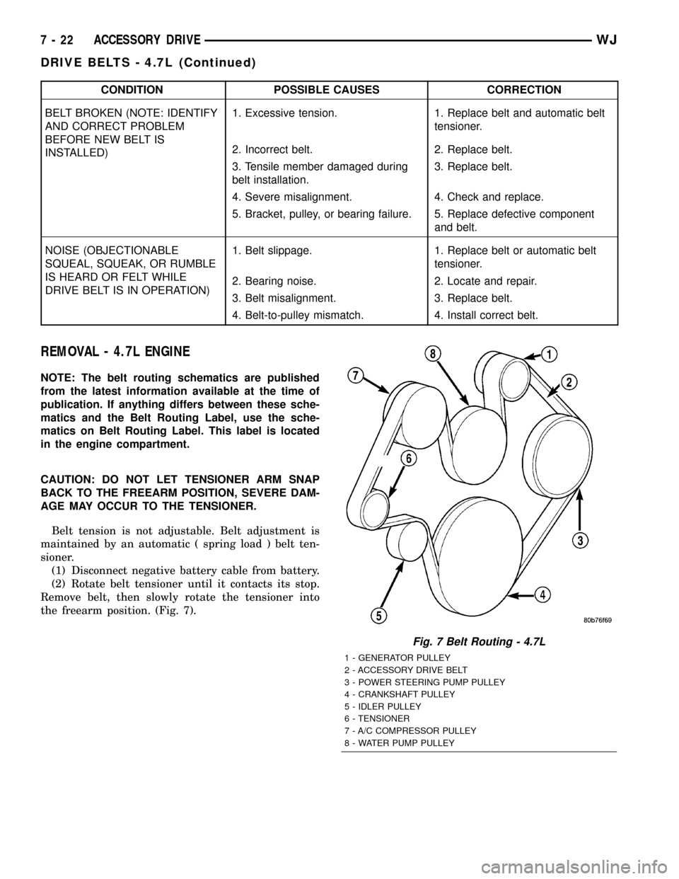
REMOVAL - 4.7L ENGINE
NOTE: The belt routing schematics are published
from the latest information available at the time of
publication. If anything differs between these sche-
matics and the Belt Routing Label, use the sche-
matics on Belt Routing Label. This label is located
in the engine compartment.
CAUTION: DO NOT LET TENSIONER ARM SNAP
BACK TO THE FREEARM POSITION, SEVERE DAM-
AGE MAY OCCUR TO THE TENSIONER.
Belt tension is not adjustable. Belt adjustment is
maintained by an automatic ( spring load ) belt ten-
sioner.
(1) Disconnect negative battery cable from battery.
(2) Rotate belt tensioner until it contacts its stop.
Remove belt, then slowly rotate the tensioner into
the freearm position. (Fig. 7).
Fig. 7 Belt Routing - 4.7L
1 - GENERATOR PULLEY
2 - ACCESSORY DRIVE BELT
3 - POWER STEERING PUMP PULLEY
4 - CRANKSHAFT PULLEY
5 - IDLER PULLEY
6 - TENSIONER
7 - A/C COMPRESSOR PULLEY
8 - WATER PUMP PULLEY
7 - 22 ACCESSORY DRIVEWJ
DRIVE BELTS - 4.7L (Continued)
Page 250 of 2199

(1) Position sensor into the coolant recovery pres-
sure container (Fig. 1).
(2) Connect the coolant level sensor electrical con-
nector (Fig. 2).
(3) Close hood.
COOLANT RECOVERY PRESS
CONTAINER
DESCRIPTION
This system works along with the radiator pres-
sure cap. This is done by using thermal expansion
and contraction of the coolant to keep the coolant
free of trapped air. It provides:
²A volume for coolant expansion and contraction.
²A convenient and safe method for checking/ad-
justing coolant level at atmospheric pressure. This is
done without removing the radiator pressure cap.
²Some reserve coolant to the radiator to cover
minor leaks and evaporation or boiling losses.
As the engine cools, a vacuum is formed in the
cooling system of both the radiator and engine. Cool-
ant will then be drawn from the coolant tank and
returned to a proper level in the radiator.
The coolant reservoir/overflow system has a radia-
tor mounted pressurized cap, an overflow tube and a
plastic coolant reservoir/overflow tank (Fig. 3)
mounted to the right inner fender.
RADIATOR FAN - 4.7L
DESCRIPTION
The hydraulic fan (Fig. 4) used on vehicles
equipped the 4.7L engine, replaces both the electric
fan and the engine driven mechanical fan. The
hydraulic cooling fan is integral to the fan shroud
and is located between the radiator and the engine.
The power steering pump supplies the hydraulic
fluid and pressure to rotate the cooling fan blade,
while the electrical part of the fan is controlled by
the JTEC.
The hydraulic fan drive (motor) consists of the
three major following components:
²Steering flow control valve
Fig. 1 COOLANT LEVEL SENSOR ELECTRICAL
CONNECTOR
Fig. 2 COOLANT LEVEL SENSOR REMOVAL/
INSTALLATION
Fig. 3 Coolant Reservoir / Overflow Tank
1 - COOLANT OVERFLOW HOSE
2 - COOLANT RESERVOIR/OVERFLOW TANK
3 - COOLANT LEVEL SENSOR
4 - BOLT
WJENGINE 7 - 27
COOLANT LEVEL SENSOR (Continued)