climate control JEEP GRAND CHEROKEE 2010 Owner handbook (in English)
[x] Cancel search | Manufacturer: JEEP, Model Year: 2010, Model line: GRAND CHEROKEE, Model: JEEP GRAND CHEROKEE 2010Pages: 350, PDF Size: 4.58 MB
Page 190 of 350
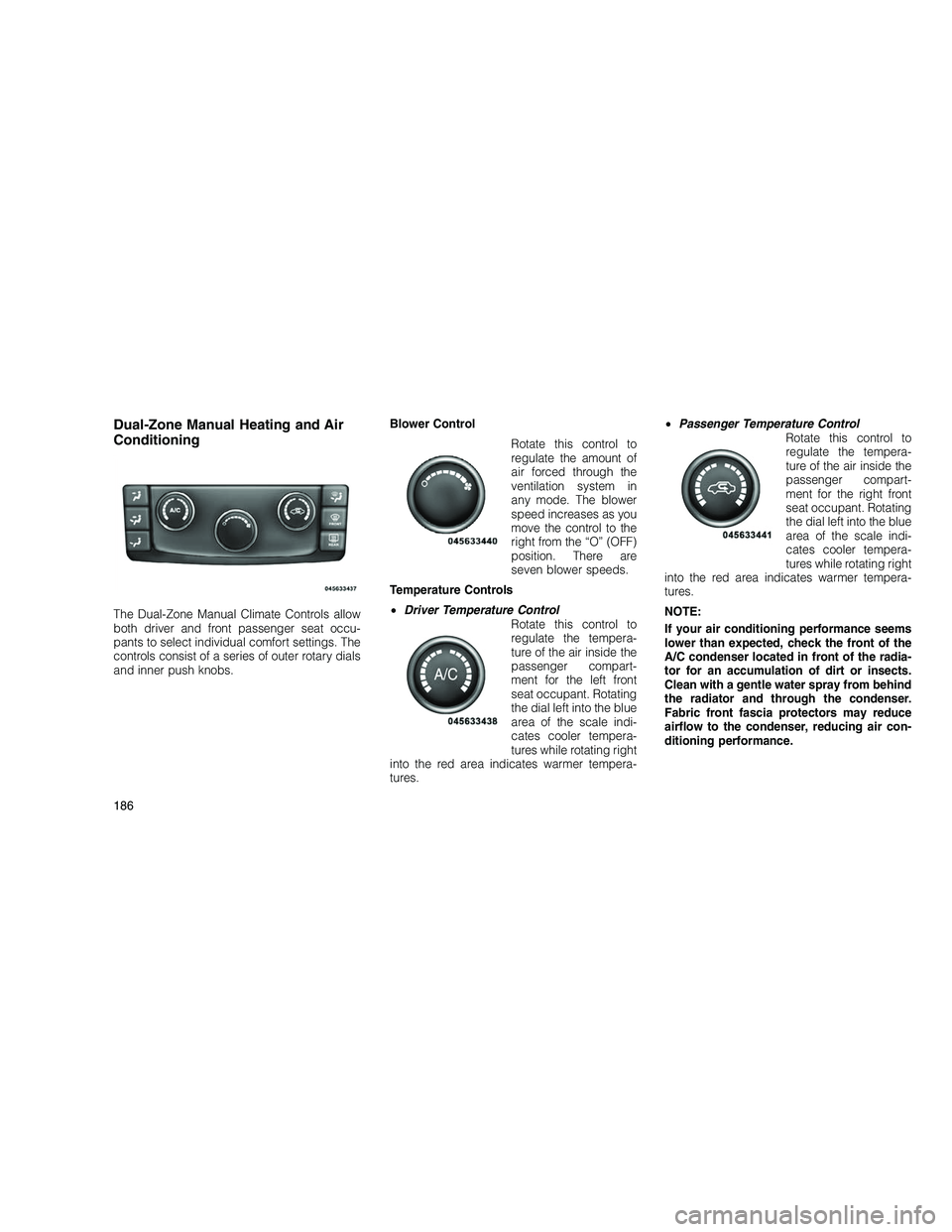
Dual-Zone Manual Heating and Air
Conditioning
The Dual-Zone Manual Climate Controls allow
both driver and front passenger seat occu-
pants to select individual comfort settings. The
controls consist of a series of outer rotary dials
and inner push knobs.Blower Control
Rotate this control to
regulate the amount of
air forced through the
ventilation system in
any mode. The blower
speed increases as you
move the control to the
right from the “O” (OFF)
position. There are
seven blower speeds.
Temperature Controls
• Driver Temperature Control
Rotate this control to
regulate the tempera-
ture of the air inside the
passenger compart-
ment for the left front
seat occupant. Rotating
the dial left into the blue
area of the scale indi-
cates cooler tempera-
tures while rotating right
into the red area indicates warmer tempera-
tures. •
Passenger Temperature Control
Rotate this control to
regulate the tempera-
ture of the air inside the
passenger compart-
ment for the right front
seat occupant. Rotating
the dial left into the blue
area of the scale indi-
cates cooler tempera-
tures while rotating right
into the red area indicates warmer tempera-
tures.
NOTE:
If your air conditioning performance seems
lower than expected, check the front of the
A/C condenser located in front of the radia-
tor for an accumulation of dirt or insects.
Clean with a gentle water spray from behind
the radiator and through the condenser.
Fabric front fascia protectors may reduce
airflow to the condenser, reducing air con-
ditioning performance.
186
Page 193 of 350
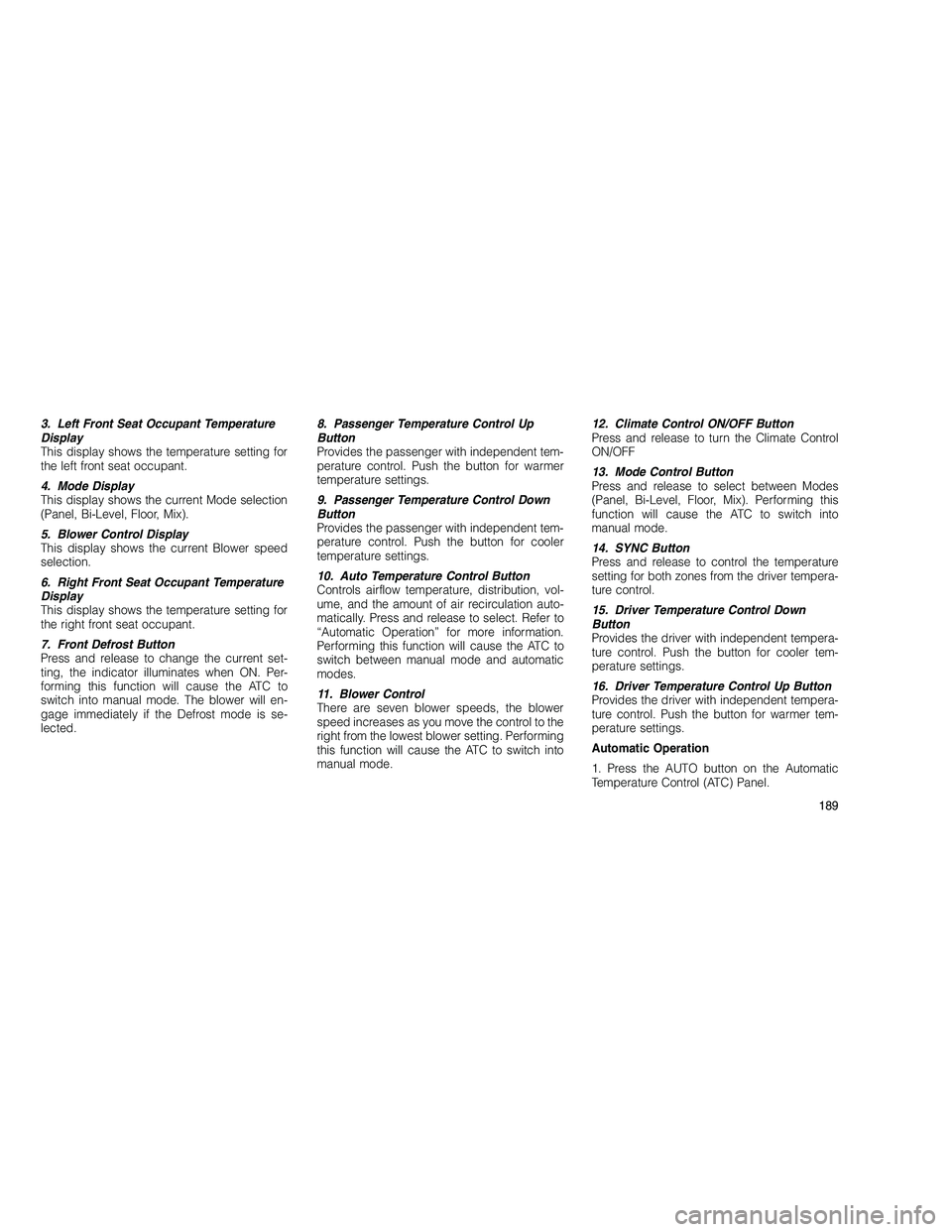
3. Left Front Seat Occupant Temperature
Display
This display shows the temperature setting for
the left front seat occupant.
4. Mode Display
This display shows the current Mode selection
(Panel, Bi-Level, Floor, Mix).
5. Blower Control Display
This display shows the current Blower speed
selection.
6. Right Front Seat Occupant Temperature
Display
This display shows the temperature setting for
the right front seat occupant.
7. Front Defrost Button
Press and release to change the current set-
ting, the indicator illuminates when ON. Per-
forming this function will cause the ATC to
switch into manual mode. The blower will en-
gage immediately if the Defrost mode is se-
lected.8. Passenger Temperature Control Up
Button
Provides the passenger with independent tem-
perature control. Push the button for warmer
temperature settings.
9. Passenger Temperature Control Down
Button
Provides the passenger with independent tem-
perature control. Push the button for cooler
temperature settings.
10. Auto Temperature Control Button
Controls airflow temperature, distribution, vol-
ume, and the amount of air recirculation auto-
matically. Press and release to select. Refer to
“Automatic Operation” for more information.
Performing this function will cause the ATC to
switch between manual mode and automatic
modes.
11. Blower Control
There are seven blower speeds, the blower
speed increases as you move the control to the
right from the lowest blower setting. Performing
this function will cause the ATC to switch into
manual mode.12. Climate Control ON/OFF Button
Press and release to turn the Climate Control
ON/OFF
13. Mode Control Button
Press and release to select between Modes
(Panel, Bi-Level, Floor, Mix). Performing this
function will cause the ATC to switch into
manual mode.
14. SYNC Button
Press and release to control the temperature
setting for both zones from the driver tempera-
ture control.
15. Driver Temperature Control Down
Button
Provides the driver with independent tempera-
ture control. Push the button for cooler tem-
perature settings.
16. Driver Temperature Control Up Button
Provides the driver with independent tempera-
ture control. Push the button for warmer tem-
perature settings.
Automatic Operation
1. Press the AUTO button on the Automatic
Temperature Control (ATC) Panel.
189
Page 262 of 350
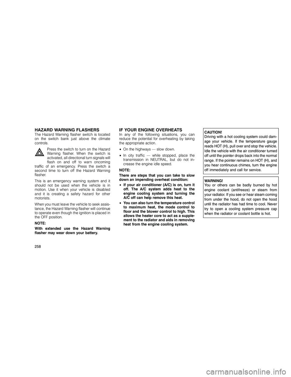
HAZARD WARNING FLASHERSThe Hazard Warning flasher switch is located
on the switch bank just above the climate
controls.Press the switch to turn on the Hazard
Warning flasher. When the switch is
activated, all directional turn signals will
flash on and off to warn oncoming
traffic of an emergency. Press the switch a
second time to turn off the Hazard Warning
flasher.
This is an emergency warning system and it
should not be used when the vehicle is in
motion. Use it when your vehicle is disabled
and it is creating a safety hazard for other
motorists.
When you must leave the vehicle to seek assis-
tance, the Hazard Warning flasher will continue
to operate even though the ignition is placed in
the OFF position.
NOTE:
With extended use the Hazard Warning
flasher may wear down your battery.IF YOUR ENGINE OVERHEATSIn any of the following situations, you can
reduce the potential for overheating by taking
the appropriate action.
• On the highways — slow down.
• In city traffic — while stopped, place the
transmission in NEUTRAL, but do not in-
crease the engine idle speed.
NOTE:
There are steps that you can take to slow
down an impending overheat condition:
• If your air conditioner (A/C) is on, turn it
off. The A/C system adds heat to the
engine cooling system and turning the
A/C off can help remove this heat.
• You can also turn the temperature control
to maximum heat, the mode control to
floor and the blower control to high. This
allows the heater core to act as a supple-
ment to the radiator and aids in removing
heat from the engine cooling system.CAUTION!
Driving with a hot cooling system could dam-
age your vehicle. If the temperature gauge
reads HOT (H), pull over and stop the vehicle.
Idle the vehicle with the air conditioner turned
off until the pointer drops back into the normal
range. If the pointer remains on HOT (H), and
you hear continuous chimes, turn the engine
off immediately and call for service.
WARNING!
You or others can be badly burned by hot
engine coolant (antifreeze) or steam from
your radiator. If you see or hear steam coming
from under the hood, do not open the hood
until the radiator has had time to cool. Never
try to open a cooling system pressure cap
when the radiator or coolant bottle is hot.
258
Page 295 of 350
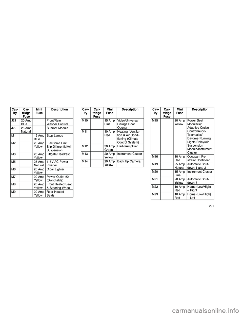
Cav-ity Car-
tridge Fuse Mini
Fuse Description
J21 20 Amp Blue Front/Rear
Washer Control
J22 25 Amp Natural Sunroof Module
M1 15 Amp BlueStop Lamps
M2 20 Amp YellowElectronic Limit
Slip Differential/Air
Suspension
M3 20 Amp YellowLiftgate/Headrest
M5 25 Amp Natural115V AC Power
Inverter
M6 20 Amp YellowCigar Lighter
M7 20 Amp YellowPower Outlet #2
(Switchable)
M8 20 Amp YellowFront Heated Seat
& Steering Wheel
M9 20 Amp YellowRear Heated
SeatsCav-
ity Car-
tridge Fuse Mini
Fuse Description
M10 15 Amp BlueVideo/Universal
Garage Door
Opener
M11 10 Amp RedHeating, Ventila-
tion & Air Condi-
tioning (Climate
Control System)
M12 30 Amp GreenRadio/Amplifier
M13 20 Amp YellowInstrument Cluster
M14 20 Amp YellowBack Up CameraCav-
ity Car-
tridge Fuse Mini
Fuse Description
M15 20 Amp YellowPower Seat
Module(s)/
Adaptive Cruise
Control/Audio
Telematics/
Daytime Running
Lights Relay/Air
Suspension
Module/Instrument
Cluster
M16 10 Amp RedOccupant Re-
straint Controller
M19 25 Amp NaturalAutomatic Shut-
down 1 and 2
M20 15 Amp BlueInstrument Cluster
M21 20 Amp YellowAutomatic Shut-
down 3
M22 10 Amp RedHorns (Low/High)
– Right
M23 10 Amp RedHorns (Low/High)
– Left
291
Page 296 of 350
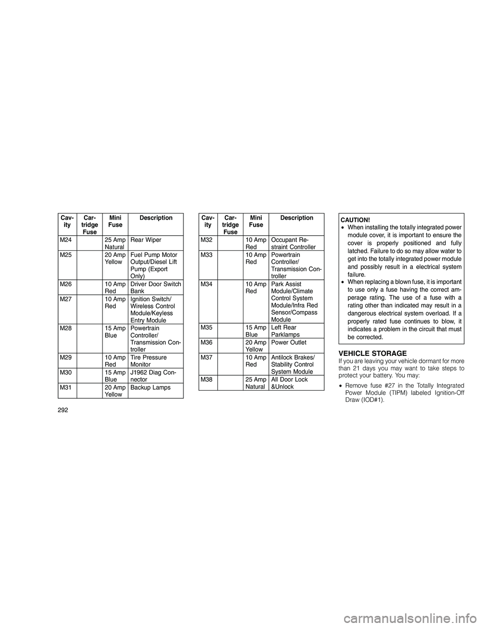
Cav-ity Car-
tridge Fuse Mini
Fuse Description
M24 25 Amp NaturalRear Wiper
M25 20 Amp YellowFuel Pump Motor
Output/Diesel Lift
Pump (Export
Only)
M26 10 Amp RedDriver Door Switch
Bank
M27 10 Amp RedIgnition Switch/
Wireless Control
Module/Keyless
Entry Module
M28 15 Amp BluePowertrain
Controller/
Transmission Con-
troller
M29 10 Amp RedTire Pressure
Monitor
M30 15 Amp BlueJ1962 Diag Con-
nector
M31 20 Amp YellowBackup LampsCav-
ity Car-
tridge Fuse Mini
Fuse Description
M32 10 Amp RedOccupant Re-
straint Controller
M33 10 Amp RedPowertrain
Controller/
Transmission Con-
troller
M34 10 Amp RedPark Assist
Module/Climate
Control System
Module/Infra Red
Sensor/Compass
Module
M35 15 Amp BlueLeft Rear
Parklamps
M36 20 Amp YellowPower Outlet
M37 10 Amp RedAntilock Brakes/
Stability Control
System Module
M38 25 Amp NaturalAll Door Lock
&UnlockCAUTION!
•
When installing the totally integrated power
module cover, it is important to ensure the
cover is properly positioned and fully
latched. Failure to do so may allow water to
get into the totally integrated power module
and possibly result in a electrical system
failure.
• When replacing a blown fuse, it is important
to use only a fuse having the correct am-
perage rating. The use of a fuse with a
rating other than indicated may result in a
dangerous electrical system overload. If a
properly rated fuse continues to blow, it
indicates a problem in the circuit that must
be corrected.
VEHICLE STORAGEIf you are leaving your vehicle dormant for more
than 21 days you may want to take steps to
protect your battery. You may:
• Remove fuse #27 in the Totally Integrated
Power Module (TIPM) labeled Ignition-Off
Draw (IOD#1).
292
Page 341 of 350
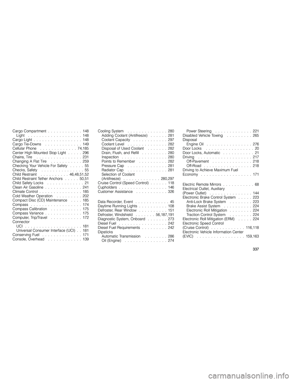
Cargo Compartment............148
Light ...................148
Cargo Light .................148
Cargo Tie-Downs .............149
Cellular Phone ............. 74,185
Center High Mounted Stop Light .....296
Chains, Tire ................231
Changing A Flat Tire ...........259
Checking Your Vehicle For Safety .....55
Checks, Safety ...............55
Child Restraint .......... 46,48,51,52
Child Restraint Tether Anchors .....50,51
Child Safety Locks .............21
Clean Air Gasoline .............241
Climate Control ...............185
Cold Weather Operation .........202
Compact Disc (CD) Maintenance ....185
Compass ..................174
Compass Calibration ...........175
Compass Variance .............175
Computer, Trip/Travel ...........172
Connector UCI ....................181
Universal Consumer Interface (UCI) . . 181
Conserving Fuel ..............171
Console, Overhead ............139 Cooling System
..............280
Adding Coolant (Antifreeze) ......281
Coolant Capacity ............297
Coolant Level ..............282
Disposal of Used Coolant .......282
Drain, Flush, and Refill .........280
Inspection ................280
Points to Remember ..........282
Pressure Cap ..............281
Radiator Cap ..............281
Selection of Coolant
(Antifreeze) ............. 280,297
Cruise Control (Speed Control) ......118
Cupholders .................146
Customer Assistance ...........326
Data Recorder, Event ............45
Daytime Running Lights ..........108
Defroster, Rear Window ..........151
Defroster, Windshield .......56,187,191
Diagnostic System, Onboard .......273
Diesel Fuel .................242
Diesel Fuel Requirements .........242
Dipsticks Automatic Transmission ........286
Oil (Engine) ...............274 Power Steering.............221
Disabled Vehicle Towing .........265
Disposal Engine Oil ................276
Door Locks .................20
Door Locks, Automatic ...........21
Driving ...................217
Off-Pavement ..............218
Off-Road .................218
Driving to Achieve Maximum Fuel
Economy ..................171
Electric Remote Mirrors ...........68
Electrical Outlet, Auxiliary
(Power Outlet) ...............144
Electronic Brake Control System .....223
Anti-Lock Brake System ........223
Brake Assist System ..........224
Electronic Roll Mitigation ........224
Traction Control System ........224
Electronic Roll Mitigation (ERM) .....224
Electronic Speed Control
(Cruise Control) ............ 116,118
Electronic Vehicle Information Center
(EVIC) ................. 159,163
337