JEEP GRAND CHEROKEE 2013 WK2 / 4.G Owners Manual
Manufacturer: JEEP, Model Year: 2013, Model line: GRAND CHEROKEE, Model: JEEP GRAND CHEROKEE 2013 WK2 / 4.GPages: 704, PDF Size: 5.14 MB
Page 311 of 704
If the light remains on when the parking brake has been
disengaged, and the fluid level is at the full mark on the
master cylinder reservoir, it indicates a possible brake
hydraulic system malfunction or that a problem with the
Brake Booster has been detected by the Anti-Lock Brake
System (ABS) / Electronic Stability Control (ESC) system.
In this case, the light will remain on until the condition
has been corrected. If the problem is related to the brake
booster, the ABS pump will run when applying the brake
and a brake pedal pulsation may be felt during each stop.
The dual brake system provides a reserve braking capac-
ity in the event of a failure to a portion of the hydraulic
system. A leak in either half of the dual brake system is
indicated by the Brake Warning Light, which will turn on
when the brake fluid level in the master cylinder has
dropped below a specified level.
The light will remain on until the cause is corrected.NOTE:The light may flash momentarily during sharp
cornering maneuvers, which change fluid level condi-
tions. The vehicle should have service performed, and
the brake fluid level checked.
If brake failure is indicated, immediate repair is neces-
sary.
WARNING!
Driving a vehicle with the red brake light on is
dangerous. Part of the brake system may have failed.
It will take longer to stop the vehicle. You could have
a collision. Have the vehicle checked immediately.
Vehicles equipped with the Anti-Lock Brake System
(ABS), are also equipped with Electronic Brake Force
Distribution (EBD). In the event of an EBD failure, the
Brake Warning Light will turn on along with the ABS
Light. Immediate repair to the ABS system is required .
4
UNDERSTANDING YOUR INSTRUMENT PANEL 309
Page 312 of 704
Operation of the Brake Warning Light can be checked by
turning the ignition switch from the OFF position to the
ON/RUN position. The light should illuminate for ap-
proximately two seconds. The light should then turn off
unless the parking brake is applied or a brake fault is
detected. If the light does not illuminate, have the light
inspected by an authorized dealer.
The light also will turn on when the parking brake is
applied with the ignition switch in the ON/RUN position.
NOTE:This light shows only that the parking brake is
applied. It does not show the degree of brake application.
15. Anti-Lock Brake (ABS) Light
This light monitors the Anti-Lock Brake System
(ABS). The light will turn on when the ignition
switch is turned to the ON/RUN position and
may stay on for as long as four seconds.If the ABS light remains on or turns on while driving, it
indicates that the Anti-Lock portion of the brake system
is not functioning and that service is required. However,
the conventional brake system will continue to operate
normally if the BRAKE warning light is not on.
If the ABS light is on, the brake system should be serviced
as soon as possible to restore the benefits of Anti-Lock
brakes. If the ABS light does not turn on when the
ignition switch is turned to the ON/RUN position, have
the light inspected by an authorized dealer.
16. 4 LOW
This light alerts the driver that the vehicle is in
the four-wheel drive LOW mode. The front and
rear driveshafts are mechanically locked to-
gether forcing the front and rear wheels to
rotate at the same speed. Low range provides a greater
gear reduction ratio to provide increased torque at the
wheels.
310 UNDERSTANDING YOUR INSTRUMENT PANEL
Page 313 of 704
For further information on four-wheel drive operation
and proper use, refer to “Four-Wheel Drive Operation —
If Equipped” in “Starting And Operating”.
17. Speedometer
Indicates vehicle speed.
18. Fuel Door Reminder
The fuel pump symbol points to the side of the
vehicle where the fuel door is located.
19. Fuel Gauge
The pointer shows the level of fuel in the fuel tank when
the ignition switch is in the ON/RUN position.20. Electronic Vehicle Information Center (EVIC) White
Telltale Area
This area will display the EVIC reconfigurable white
telltales. For further information, refer to “Electronic
vehicle Information Center (EVIC)”.
21. Electronic Vehicle Information Center (EVIC) Amber
Telltale Area
This area will display the EVIC reconfigurable amber
caution telltales. For further information, refer to “Elec-
tronic vehicle Information Center (EVIC)”.
22. Electronic Vehicle Information Center (EVIC) Red
Telltale Area
This area will display the EVIC reconfigurable red tell-
tales. For further information, refer to “Electronic vehicle
Information Center (EVIC)”
4
UNDERSTANDING YOUR INSTRUMENT PANEL 311
Page 314 of 704
23. Electronic Stability Control (ESC) OFF Indicator
Light — If Equipped
This light indicates the Electronic Stability Con-
trol (ESC) is off.
24. Vehicle Security Light
This light will flash rapidly for approximately
15 seconds when the vehicle theft alarm is
arming. The light will flash at a slower speed
continuously after the alarm is set. The security
light will also come on for about three seconds when the
ignition is first turned on.
25. Temperature Gauge
The temperature gauge shows engine coolant tempera-
ture. Any reading within the normal range indicates that
the engine cooling system is operating satisfactorily.The gauge pointer will likely indicate a higher tempera-
ture when driving in hot weather, up mountain grades,
or when towing a trailer. It should not be allowed to
exceed the upper limits of the normal operating range.
CAUTION!
Driving with a hot engine cooling system could
damage your vehicle. If the temperature gauge reads
“H” pull over and stop the vehicle. Idle the vehicle
with the air conditioner turned off until the pointer
drops back into the normal range. If the pointer
remains on the “H” and you hear continuous chimes,
turn the engine off immediately and call an autho-
rized dealer for service.
312 UNDERSTANDING YOUR INSTRUMENT PANEL
Page 315 of 704
WARNING!
A hot engine cooling system is dangerous. You or
others could be badly burned by steam or boiling
coolant. You may want to call an authorized dealer
for service if your vehicle overheats. If you decide to
look under the hood yourself, see “Maintaining Your
Vehicle”. Follow the warnings under the Cooling
System Pressure Cap paragraph.
ELECTRONIC VEHICLE INFORMATION CENTER
(EVIC)
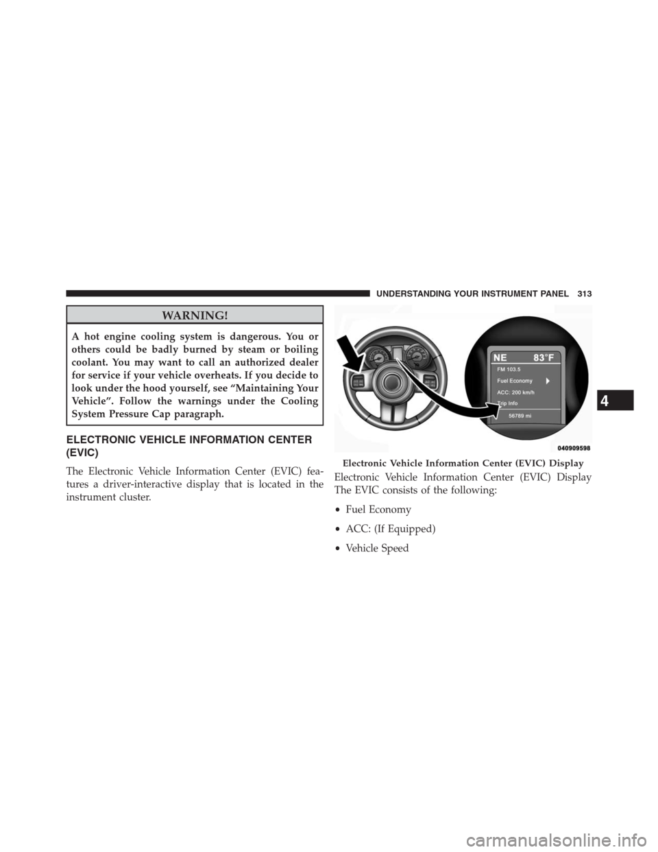
The Electronic Vehicle Information Center (EVIC) fea-
tures a driver-interactive display that is located in the
instrument cluster.Electronic Vehicle Information Center (EVIC) Display
The EVIC consists of the following:
•Fuel Economy
•ACC: (If Equipped)
•Vehicle SpeedElectronic Vehicle Information Center (EVIC) Display
4
UNDERSTANDING YOUR INSTRUMENT PANEL 313
Page 316 of 704
•Trip Info
•Terrain: (If Equipped)
•Tire PSI: (If Equipped)
•Vehicle Info
•Messages
•UNITS: SETTING
•System Setup
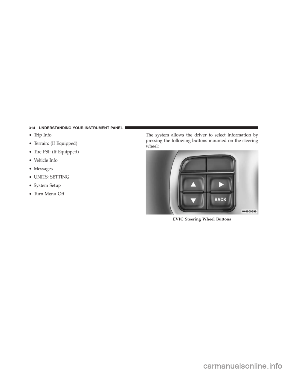
•Turn Menu OffThe system allows the driver to select information by
pressing the following buttons mounted on the steering
wheel:
EVIC Steering Wheel Buttons
314 UNDERSTANDING YOUR INSTRUMENT PANEL
Page 317 of 704
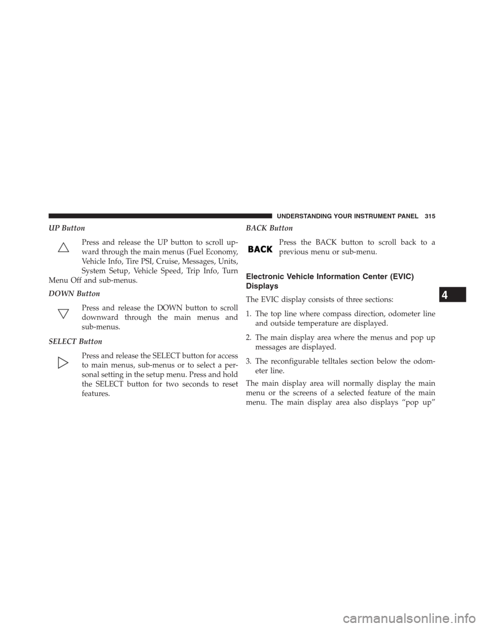
UP Button
Press and release the UP button to scroll up-
ward through the main menus (Fuel Economy,
Vehicle Info, Tire PSI, Cruise, Messages, Units,
System Setup, Vehicle Speed, Trip Info, Turn
Menu Off and sub-menus.
DOWN Button
Press and release the DOWN button to scroll
downward through the main menus and
sub-menus.
SELECT Button
Press and release the SELECT button for access
to main menus, sub-menus or to select a per-
sonal setting in the setup menu. Press and hold
the SELECT button for two seconds to reset
features.BACK Button
Press the BACK button to scroll back to a
previous menu or sub-menu.
Electronic Vehicle Information Center (EVIC)
Displays
The EVIC display consists of three sections:
1. The top line where compass direction, odometer line
and outside temperature are displayed.
2. The main display area where the menus and pop up
messages are displayed.
3. The reconfigurable telltales section below the odom-
eter line.
The main display area will normally display the main
menu or the screens of a selected feature of the main
menu. The main display area also displays “pop up”4
UNDERSTANDING YOUR INSTRUMENT PANEL 315
Page 318 of 704

messages that consist of approximately 60 possible warn-
ing or information messages. These pop up messages fall
into several categories:
he reconfigurable Telltales section is divided into the
white telltales area on the right, amber telltales in the
middle, and red telltales on the left.
•Five Second Stored Messages
When the appropriate conditions occur, this type of
message takes control of the main display area for five
seconds and then returns to the previous screen. Most of
the messages of this type are then stored (as long as the
condition that activated it remains active) and can be
reviewed from the “Messages” main menu item. As long
as there is a stored message, an ”i” will be displayed in
the EVIC’s compass/outside temp line. Examples of this
message type are “Right Front Turn Signal Lamp Out”
and “Low Tire Pressure”.•Unstored Messages
This message type is displayed indefinitely or until the
condition that activated the message is cleared. Examples
of this message type are “Turn Signal On” (if a turn signal
is left on) and “Lights On” (if driver leaves the vehicle).
•Unstored Messages Until RUN
These messages deal primarily with the Remote Start
feature. This message type is displayed until the ignition
is in the RUN state. Examples of this message type are
“Remote Start Aborted - Door Ajar” and “Press Brake
Pedal and Push Button to Start”.
•Five Second Unstored
When the appropriate conditions occur, this type of mes-
sage takes control of the main display area for five seconds
and then returns to the previous screen. Examples of this
message type are “Memory System Unavailable - Not in
Park” and “Automatic High Beams On”.
316 UNDERSTANDING YOUR INSTRUMENT PANEL
Page 319 of 704
When the appropriate conditions exist, the EVIC displays
the following messages:
•Vehicle Not in Park
•Key Left Vehicle
•Key Not Detected
•Service TPM System (refer to “Tire Pressure Monitor-
ing System” in “Starting And Operating”)
•Premium TPM System Graphic Display
•Service Keyless System (refer to Keyless Enter-N-Go™,
Passive Entry - if equipped)
•Service Park Assist System
•Park Assist System Blinded
•Park Assist Disabled
•Keyfob Battery Low
•Liftglass Open•Left front turn signal lamp out
•Right front turn signal lamp out
•Left rear turn signal lamp out
•Right rear turn signal lamp out
•Low Tire Pressure
•ESC System Off
•Service blind spot system
•Blind spot detection unavailable
•Blind spot system off
•Blind spot system unavailable sensor blocked
•Normal Cruise Ready — When Adaptive Cruise Con-
trol (ACC) system is turned off and Normal (Fixed
Speed) Cruise Control mode is available. Refer to
“Adaptive Cruise Control (ACC)” in “Understanding
The Features Of Your Vehicle” (if equipped).
4
UNDERSTANDING YOUR INSTRUMENT PANEL 317
Page 320 of 704

•Adaptive Cruise Off — When the Adaptive Cruise
Control (ACC) system is turned off. Refer to “Adaptive
Cruise Control (ACC)” in “Understanding The Fea-
tures Of Your Vehicle” (if equipped).
•ACC Ready — When the ACC system is activated.
Refer to “Adaptive Cruise Control (ACC)” in “Under-
standing The Features Of Your Vehicle” (if equipped).
•ACC Set — After setting the desired speed in the ACC
system. Refer to “Adaptive Cruise Control (ACC)” in
“Understanding The Features Of Your Vehicle” (if
equipped).
•ACC Cancelled — To disable the ACC system. Refer to
“Adaptive Cruise Control (ACC)” in “Understanding
The Features Of Your Vehicle” (if equipped).
•Sensed Vehicle Indicator — The system detects a
slower moving vehicle in the same lane. Refer to
“Adaptive Cruise Control (ACC)” in “Understanding
The Features Of Your Vehicle” (if equipped).•Driver Override — If you apply the accelerator after
setting the desired speed in the ACC system. Refer to
“Adaptive Cruise Control (ACC)” in “Understanding
The Features Of Your Vehicle” (if equipped).
•Distance Set — After changing the desired following
distance in the ACC system, this message will display
momentarily. Refer to “Adaptive Cruise Control
(ACC)” in “Understanding The Features Of Your Ve-
hicle” (if equipped).
•Brake — If the ACC system predicts that its maximum
braking level is not sufficient to maintain the set
distance, this message will flash and a chime will
sound while ACC continues to apply its maximum
braking capacity. When this occurs, you should imme-
diately apply the brakes as needed to maintain a safe
distance from the vehicle ahead. Refer to “Adaptive
Cruise Control (ACC)” in “Understanding The Fea-
tures Of Your Vehicle” (if equipped).
318 UNDERSTANDING YOUR INSTRUMENT PANEL