ignition JEEP GRAND CHEROKEE 2016 WK2 / 4.G Owner's Guide
[x] Cancel search | Manufacturer: JEEP, Model Year: 2016, Model line: GRAND CHEROKEE, Model: JEEP GRAND CHEROKEE 2016 WK2 / 4.GPages: 276, PDF Size: 10.84 MB
Page 194 of 276
Your vehicle has also been equipped with a TPMS malfunction indicator to indicate
when the system is not operating properly. The TPMS malfunction indicator is
combined with the low tire pressure telltale. When the system detects a malfunction,
the telltale will flash for approximately one minute and then remain continuously
illuminated. This sequence will continue each time the vehicle is restarted as long as
the malfunction exists.
When the malfunction indicator is illuminated, the system may not be able to detect
or signal low tire pressure as intended. TPMS malfunctions may occur for a variety of
reasons, including the installation of replacement or alternate tires or wheels on the
vehicle that prevent the TPMS from functioning properly. Always check the TPMS
malfunction telltale after replacing one or more tires or wheels on your vehicle, to
ensure that the replacement or alternate tires and wheels allow the TPMS to continue
to function properly.
NOTE:
Tire pressures change by approximately 1 psi (7 kPa) per 12° F (7° C) of air
temperature change. Keep this in mind when checking tire pressure inside a garage,
especially in the Winter. Example: If garage temperature is 68°F (20°C) and the
outside temperature is 32°F (0°C), then the cold tire inflation pressure should be
increased by 3 psi (21 kPa), which equals 1 psi (7 kPa) for every 12°F (7°C) for this
outside temperature condition.
CAUTION!
The TPMS has been optimized for the original equipment tires and wheels. TPMS
pressures and warning have been established for the tire size equipped on your
vehicle. Undesirable system operation or sensor damage may result when using
replacement equipment that is not of the same size, type, and/or style. Aftermar-
ket wheels can cause sensor damage. Do not use tire sealant from a can, or
balance beads if your vehicle is equipped with a TPMS, as damage to the sensors
may result.
– Seat Belt Reminder Light
When the ignition switch is first turned to the ON/RUN position, this light will turn on
for four to eight seconds as a bulb check. During the bulb check, if the driver's seat
belt is unbuckled, a chime will sound. After the bulb check or when driving, if the
driver or front passenger seat belt remains unbuckled, the Seat Belt Indicator Light
will flash or remain on continuously. Refer to “Seat Belt Systems” in “Things To
Know Before Starting” in your Owner’s Manual on the DVD for further information.
WHAT TO DO IN EMERGENCIES
192
Page 195 of 276
– Brake Warning Light
This light monitors various brake functions, including brake fluid level and parking
brake application. If the brake light turns on, it may indicate that the parking brake
is applied, that the brake fluid level is low, or that there is a problem with the brake
system master cylinder reservoir.
If the light remains on when the parking brake has been disengaged, and the fluid
level is at the full mark on the master cylinder reservoir, it indicates a possible brake
hydraulic system malfunction or that a problem with the Brake Booster has been
detected by the Anti-Lock Brake System (ABS)/Electronic Stability Control (ESC)
system. In this case, the light will remain on until the condition has been corrected.
If the problem is related to the brake booster, the ABS pump will run when applying
the brake, and a brake pedal pulsation may be felt during each stop.
The dual brake system provides a reserve braking capacity in the event of a failure to
a portion of the hydraulic system. A leak in either half of the dual brake system is
indicated by the Brake Warning Light, which will turn on when the brake fluid level
in the master cylinder has dropped below a specified level. The light will remain on
until the cause is corrected.
Vehicles equipped with the Anti-Lock Brake System (ABS) are also equipped with
Electronic Brake Force Distribution (EBD). In the event of an EBD failure, the Brake
Warning Light will turn on along with the ABS Light. Immediate repair to the ABS
system is required.
Operation of the Brake Warning Light can be checked by turning the ignition switch
from the OFF position to the ON/RUN position. The light should illuminate for
approximately two seconds. The light should then turn off unless the parking brake
is applied or a brake fault is detected. If the light does not illuminate, have the light
inspected by an authorized dealer.
The light also will turn on when the parking brake is applied with the ignition switch
in the ON/RUN position.
NOTE:
This light shows only that the parking brake is applied. It does not show the degree
of brake application.
WARNING!
Driving a vehicle with the red brake light on is dangerous. Part of the brake system
may have failed. It will take longer to stop the vehicle. You could have a collision.
Have the vehicle checked immediately.
WHAT TO DO IN EMERGENCIES
193
Page 196 of 276
– Malfunction Indicator Light (MIL)
The Malfunction Indicator Light (MIL) is part of an onboard diagnostic system called
OBD II that monitors engine and automatic transmission control systems. The light
will illuminate when the key is in the ON/RUN position before engine start. If the bulb
does not come on when turning the key from OFF to ON/RUN, have the condition
checked promptly.
Certain conditions, poor fuel quality, etc., may illuminate the light after engine start.
The vehicle should be serviced if the light stays on through several of your typical
driving cycles. In most situations, the vehicle will drive normally and will not require
towing.
CAUTION!
Prolonged driving with the Malfunction Indicator Light (MIL) on could cause
damage to the engine control system. It also could affect fuel economy and
driveability. If the MIL is flashing, severe catalytic converter damage and power
loss will soon occur. Immediate service is required.
WARNING!
A malfunctioning catalytic converter, as referenced above, can reach higher
temperatures than in normal operating conditions. This can cause a fire if you
drive slowly or park over flammable substances such as dry plants, wood,
cardboard, etc. This could result in death or serious injury to the driver, occupants
or others.
– Electronic Stability Control (ESC) Activation/Malfunction Indicator Light
The “ESC Activation/Malfunction Indicator Light” in the instrument cluster will
come on when the ignition switch is turned to the ON/RUN position. It should go out
with the engine running. If the “ESC Activation/Malfunction Indicator Light” comes
on continuously with the engine running, a malfunction has been detected in the ESC
system. If this light remains on after several ignition cycles, and the vehicle has been
driven several miles (kilometers) at speeds greater than 30 mph (48 km/h), see your
authorized dealer as soon as possible to have the problem diagnosed and corrected.
NOTE:
• The “ESC Off Indicator Light” and the “ESC Activation/Malfunction IndicatorLight” come on momentarily each time the ignition switch is turned to ON/RUN.
• Each time the ignition is turned to ON/RUN, the ESC system will be ON, even if it was turned off previously.
• The ESC system will make buzzing or clicking sounds when it is active. This is normal; the sounds will stop when ESC becomes inactive following the maneuver
that caused the ESC activation.
WHAT TO DO IN EMERGENCIES
194
Page 197 of 276
• To improve the vehicle's traction when starting off in deep snow, sand or gravel, itmay be desirable to switch the ESC system to Partial Off mode by momentarily
pushing the ESC Off
switch located below the climate controls, on the switch
panel.
INSTRUMENT CLUSTER INDICATOR LIGHTS
– Low Fuel Warning Light
This warning light indicates when the fuel level reaches approximately 1.5 gal
(5.8 L). This light will turn on and a single chime will sound.
– Turn Signal Indicator
The arrows will flash with the exterior turn signals when the turn signal lever is
operated. A tone will chime, and a DID message will appear if either turn signal is left
on for more than 1 mile (1.6 km).
NOTE:
If either indicator flashes at a rapid rate, check for a defective outside light bulb.
– High Beam Indicator
Indicates that headlights are on high beam.
– Front Fog Light Indicator
This indicator will illuminate when the front fog lights are on.
– Park/Headlight ON Indicator
This indicator will illuminate when the park lights or headlights are turned on.
– Vehicle Security Light
This light will flash rapidly for approximately 15 seconds when the vehicle security
alarm is arming. The light will flash at a slower speed continuously after the alarm is
set. The security light will also come on for about three seconds when the ignition is
first turned on.
– Electronic Speed Control ON Indicator
This indicator will illuminate when the electronic speed control has been activated to
the “ON” position.
– Electronic Speed Control SET Indicator
This indicator will illuminate when the cruising speed has been set.
– Hill Descent Control Indicator — If Equipped
This indicator will illuminate when Hill Descent Control (HDC) has been selected
using the Hill Descent Control Switch.
WHAT TO DO IN EMERGENCIES
195
Page 198 of 276
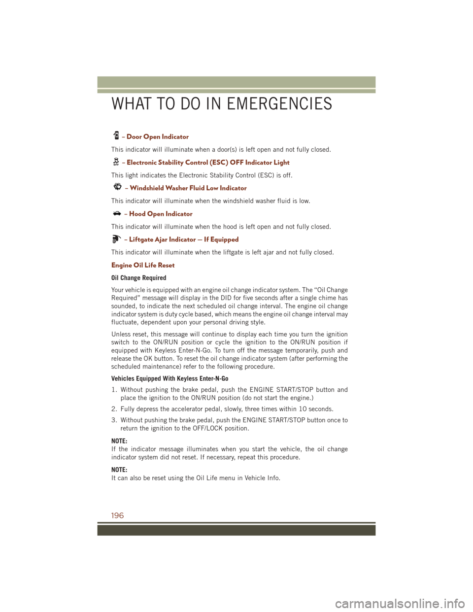
– Door Open Indicator
This indicator will illuminate when a door(s) is left open and not fully closed.
– Electronic Stability Control (ESC) OFF Indicator Light
This light indicates the Electronic Stability Control (ESC) is off.
– Windshield Washer Fluid Low Indicator
This indicator will illuminate when the windshield washer fluid is low.
– Hood Open Indicator
This indicator will illuminate when the hood is left open and not fully closed.
– Liftgate Ajar Indicator — If Equipped
This indicator will illuminate when the liftgate is left ajar and not fully closed.
Engine Oil Life Reset
Oil Change Required
Your vehicle is equipped with an engine oil change indicator system. The “Oil Change
Required” message will display in the DID for five seconds after a single chime has
sounded, to indicate the next scheduled oil change interval. The engine oil change
indicator system is duty cycle based, which means the engine oil change interval may
fluctuate, dependent upon your personal driving style.
Unless reset, this message will continue to display each time you turn the ignition
switch to the ON/RUN position or cycle the ignition to the ON/RUN position if
equipped with Keyless Enter-N-Go. To turn off the message temporarily, push and
release the OK button. To reset the oil change indicator system (after performing the
scheduled maintenance) refer to the following procedure.
Vehicles Equipped With Keyless Enter-N-Go
1. Without pushing the brake pedal, push the ENGINE START/STOP button andplace the ignition to the ON/RUN position (do not start the engine.)
2. Fully depress the accelerator pedal, slowly, three times within 10 seconds.
3. Without pushing the brake pedal, push the ENGINE START/STOP button once to return the ignition to the OFF/LOCK position.
NOTE:
If the indicator message illuminates when you start the vehicle, the oil change
indicator system did not reset. If necessary, repeat this procedure.
NOTE:
It can also be reset using the Oil Life menu in Vehicle Info.
WHAT TO DO IN EMERGENCIES
196
Page 202 of 276
Preparations For Jacking
CAUTION!
Always lift or jack the vehicle from the correct jacking points. Failure to follow this
information could cause damage to the vehicle or underbody components.
NOTE:
To assist with changing a spare tire, the air suspension system (if equipped) has a
feature which allows the automatic leveling to be disabled.
1. Park the vehicle on a firm, level surface. Avoid ice or slippery surfaces.
WARNING!
Do not attempt to change a tire on the side of the vehicle closest to moving traffic,
pull far enough off the road to avoid being hit when operating the jack or changing
the wheel.
2. Turn on the Hazard Warning flasher.
3. Set the parking brake.
4. Place the gear selector into PARK.
5. Turn the ignition OFF.
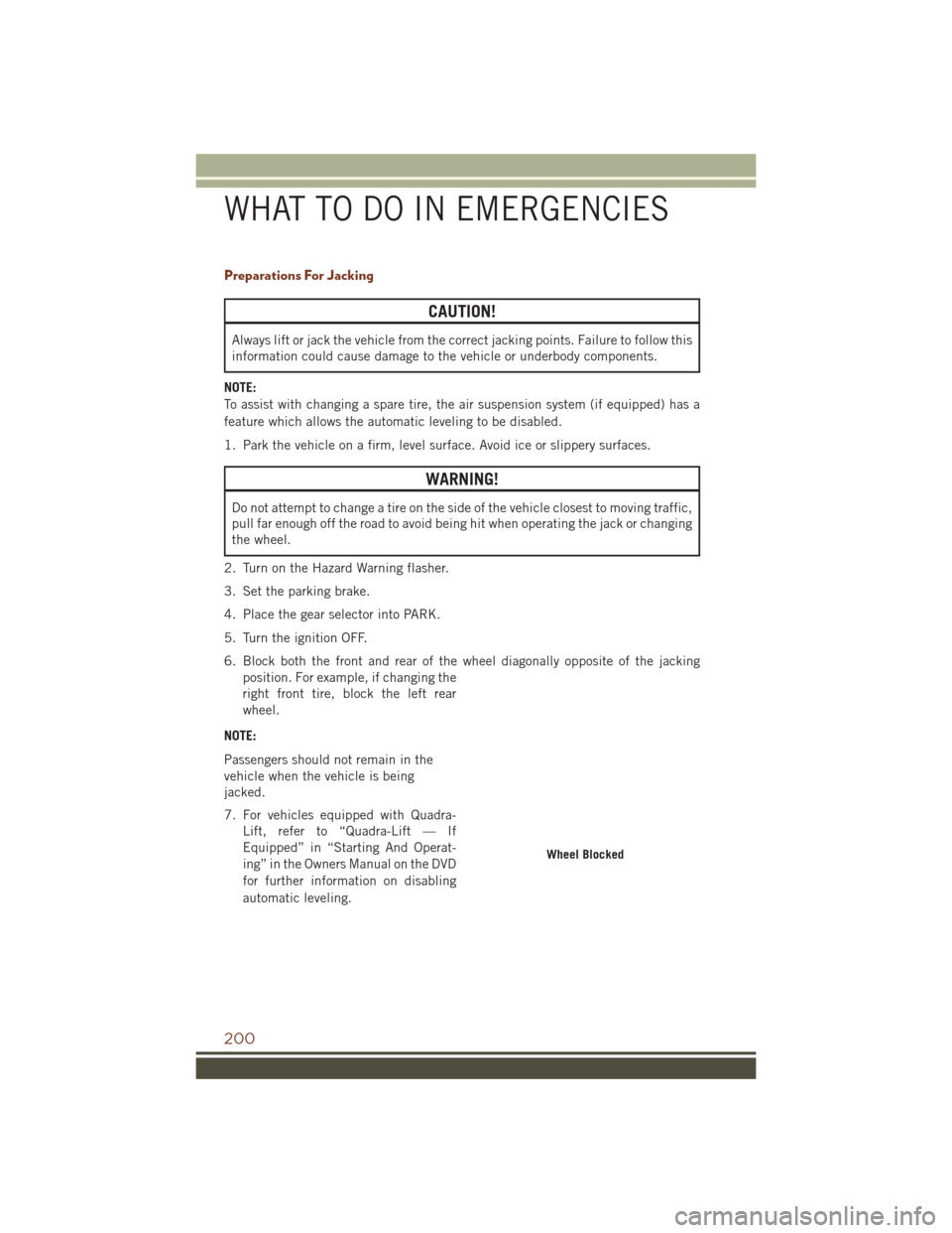
6. Block both the front and rear of the wheel diagonally opposite of the jacking position. For example, if changing the
right front tire, block the left rear
wheel.
NOTE:
Passengers should not remain in the
vehicle when the vehicle is being
jacked.
7. For vehicles equipped with Quadra- Lift, refer to “Quadra-Lift — If
Equipped” in “Starting And Operat-
ing” in the Owners Manual on the DVD
for further information on disabling
automatic leveling.
Wheel Blocked
WHAT TO DO IN EMERGENCIES
200
Page 209 of 276
Preparations For Jump-Start
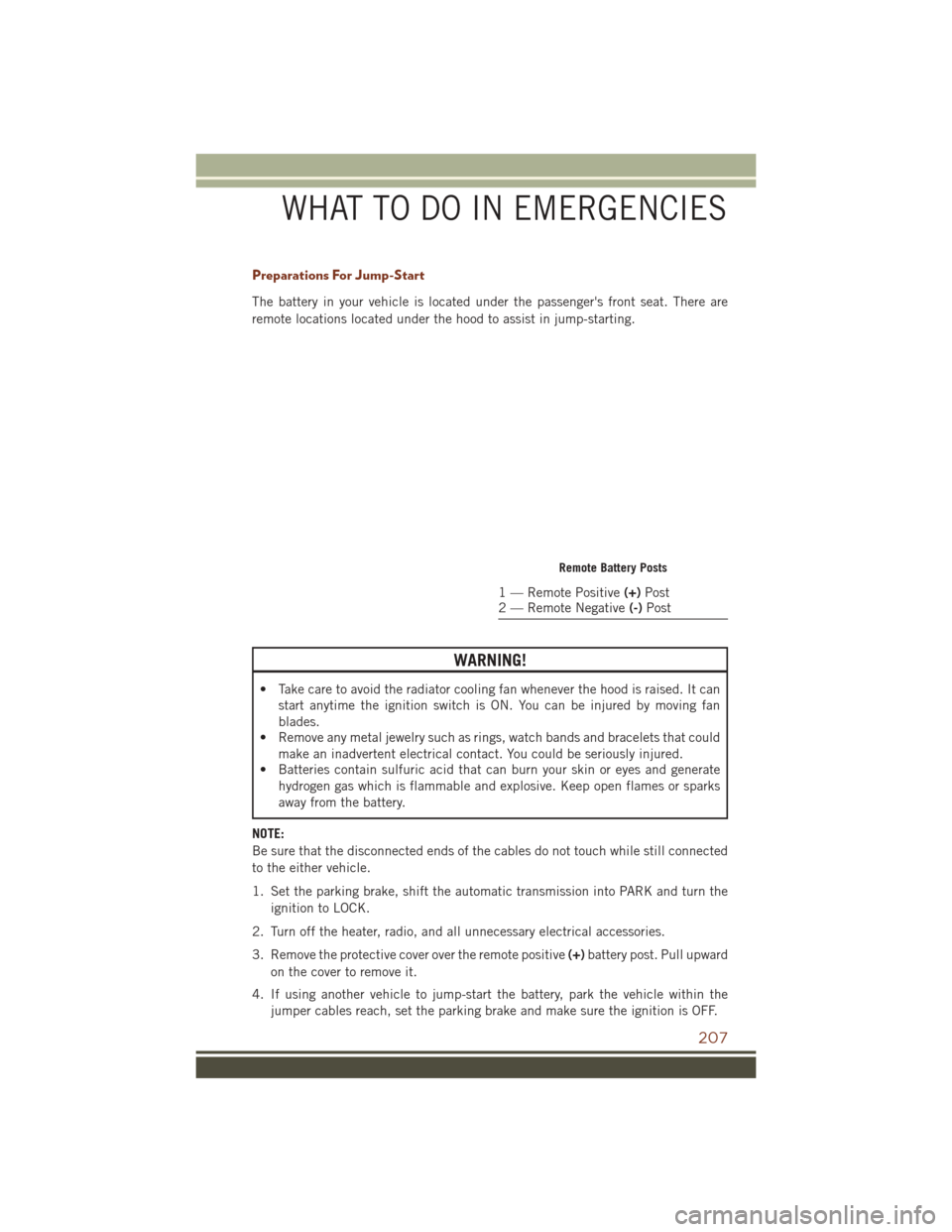
The battery in your vehicle is located under the passenger's front seat. There are
remote locations located under the hood to assist in jump-starting.
WARNING!
• Take care to avoid the radiator cooling fan whenever the hood is raised. It canstart anytime the ignition switch is ON. You can be injured by moving fan
blades.
• Remove any metal jewelry such as rings, watch bands and bracelets that could
make an inadvertent electrical contact. You could be seriously injured.
• Batteries contain sulfuric acid that can burn your skin or eyes and generate
hydrogen gas which is flammable and explosive. Keep open flames or sparks
away from the battery.
NOTE:
Be sure that the disconnected ends of the cables do not touch while still connected
to the either vehicle.
1. Set the parking brake, shift the automatic transmission into PARK and turn the ignition to LOCK.
2. Turn off the heater, radio, and all unnecessary electrical accessories.
3. Remove the protective cover over the remote positive (+)battery post. Pull upward
on the cover to remove it.
4. If using another vehicle to jump-start the battery, park the vehicle within the jumper cables reach, set the parking brake and make sure the ignition is OFF.
Remote Battery Posts
1 — Remote Positive (+)Post
2 — Remote Negative (-)Post
WHAT TO DO IN EMERGENCIES
207
Page 215 of 276
If you must use the accessories (wipers, defrosters, etc.) while being towed, the
ignition must be in the ON/RUN position, not the ACC position.
If the key fob is unavailable, or the vehicle's battery is discharged, refer to “Manual
Park Release” in this section for instructions on shifting the transmission out of
PARK for towing.
CAUTION!
• Do not use sling type equipment when towing. Vehicle damage may occur.
• When securing the vehicle to a flat bed truck, do not attach to front or rearsuspension components. Damage to your vehicle may result from improper
towing.
Two-Wheel Drive Models
The manufacturer recommends towing your vehicle with all four wheels OFFthe
ground using a flatbed.
If flatbed equipment is not available, and the transmission is operable, the vehicle
may be towed (with rear wheels on the ground) under the following conditions:
• The transmission must be in NEUTRAL. Refer to "Manual Park Release" in this section for instructions on shifting the transmission to NEUTRAL when the engine
is off.
• The towing speed must not exceed 30 mph (48 km/h).
• The towing distance must not exceed 30 miles (48 km).
If the transmission is not operable, or the vehicle must be towed faster than 30 mph
(48 km/h) or farther than 30 miles (48 km), tow with the rear wheels OFFthe ground.
Acceptable methods are to tow the vehicle on a flatbed, or with the front wheels
raised and the rear wheels on a towing dolly, or (when using a suitable steering wheel
stabilizer to hold the front wheels in the straight position) with the rear wheels raised
and the front wheels on the ground.
CAUTION!
Towing faster than 30 mph (48 km/h) or farther than 30 miles (48 km) with rear
wheels on the ground can cause severe transmission damage. Damage from
improper towing is not covered under the New Vehicle Limited Warranty.
WHAT TO DO IN EMERGENCIES
213
Page 252 of 276
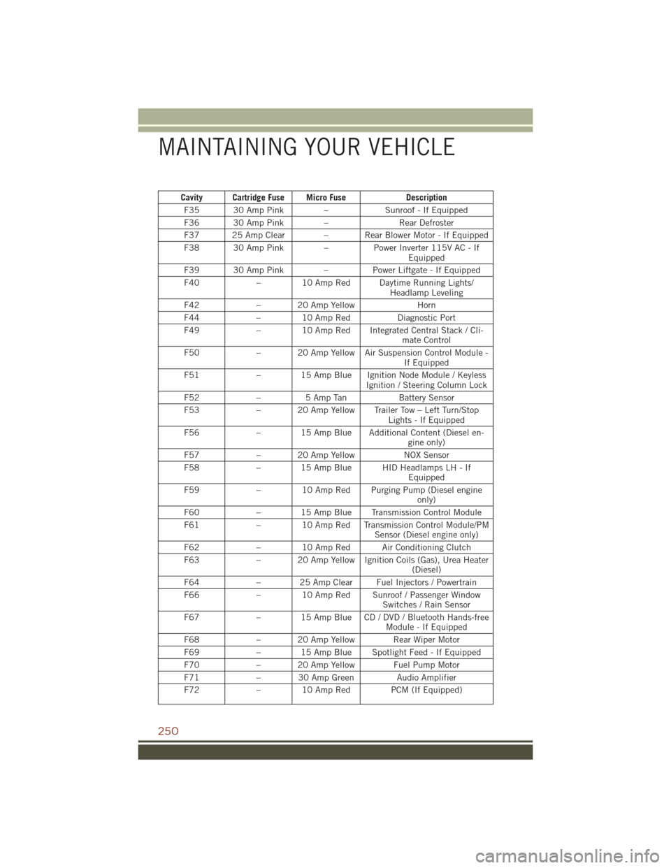
Cavity Cartridge Fuse Micro FuseDescription
F35 30 Amp Pink – Sunroof - If Equipped
F36 30 Amp Pink – Rear Defroster
F37 25 Amp Clear – Rear Blower Motor - If Equipped
F38 30 Amp Pink – Power Inverter 115V AC - If
Equipped
F39 30 Amp Pink – Power Liftgate - If Equipped
F40 – 10 Amp Red Daytime Running Lights/
Headlamp Leveling
F42 – 20 Amp Yellow Horn
F44 – 10 Amp Red Diagnostic Port
F49 – 10 Amp Red Integrated Central Stack / Cli-
mate Control
F50 – 20 Amp Yellow Air Suspension Control Module -
If Equipped
F51 – 15 Amp Blue Ignition Node Module / Keyless
Ignition / Steering Column Lock
F52 –5 Amp Tan Battery Sensor
F53 – 20 Amp Yellow Trailer Tow – Left Turn/Stop
Lights - If Equipped
F56 – 15 Amp Blue Additional Content (Diesel en-
gine only)
F57 – 20 Amp Yellow NOX Sensor
F58 – 15 Amp Blue HID Headlamps LH - If
Equipped
F59 – 10 Amp Red Purging Pump (Diesel engine
only)
F60 – 15 Amp Blue Transmission Control Module
F61 – 10 Amp Red Transmission Control Module/PM
Sensor (Diesel engine only)
F62 – 10 Amp Red Air Conditioning Clutch
F63 – 20 Amp Yellow Ignition Coils (Gas), Urea Heater
(Diesel)
F64 – 25 Amp Clear Fuel Injectors / Powertrain
F66 – 10 Amp Red Sunroof / Passenger Window
Switches / Rain Sensor
F67 – 15 Amp Blue CD / DVD / Bluetooth Hands-free
Module - If Equipped
F68 – 20 Amp Yellow Rear Wiper Motor
F69 – 15 Amp Blue Spotlight Feed - If Equipped
F70 – 20 Amp Yellow Fuel Pump Motor
F71 – 30 Amp Green Audio Amplifier
F72 – 10 Amp Red PCM (If Equipped)
MAINTAINING YOUR VEHICLE
250