ECO mode JEEP GRAND CHEROKEE 2016 WK2 / 4.G User Guide
[x] Cancel search | Manufacturer: JEEP, Model Year: 2016, Model line: GRAND CHEROKEE, Model: JEEP GRAND CHEROKEE 2016 WK2 / 4.GPages: 276, PDF Size: 10.84 MB
Page 3 of 276
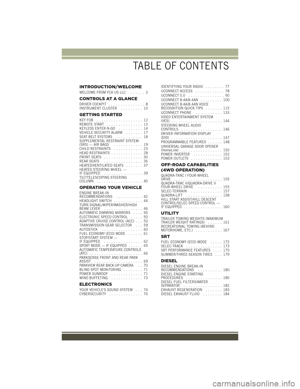
INTRODUCTION/WELCOME
WELCOME FROM FCA US LLC...... 3
CONTROLS AT A GLANCE
DRIVER COCKPIT............... 8
INSTRUMENT CLUSTER ......... 10
GETTING STARTED
KEYFOB ................... 12
REMOTE START............... 13
KEYLESS ENTER-N-GO .......... 14
VEHICLE SECURITY ALARM ....... 17
SEAT BELT SYSTEMS ........... 18
SUPPLEMENTAL RESTRAINT SYSTEM
(SRS) — AIR BAGS ............ 19
CHILD RESTRAINTS ............ 23
HEAD RESTRAINTS ............. 28
FRONT SEATS ................ 30
REAR SEATS ................ 36
HEATED/VENTILATED SEATS ....... 37
HEATED STEERING WHEEL —
IF EQUIPPED ................ 39
TILT/TELESCOPING STEERING
COLUMN ................... 40
OPERATING YOUR VEHICLE
ENGINE BREAK-IN
RECOMMENDATIONS ........... 42
HEADLIGHT SWITCH ............ 44
TURN SIGNAL/WIPER/WASHER/HIGH
BEAM LEVER ................ 46
AUTOMATIC DIMMING MIRRORS .... 50
ELECTRONIC SPEED CONTROL ..... 50
ADAPTIVE CRUISE CONTROL (ACC) . . . 53
TRANSMISSION GEAR SELECTOR . . . 59
AUTOSTICK ................. 60
FUEL ECONOMY (ECO) MODE ...... 61
STOP/START SYSTEM —
IF EQUIPPED ................ 62
SPORT MODE — IF EQUIPPED ...... 65
AUTOMATIC TEMPERATURE CONTROLS
(ATC) ...................... 66
PARKSENSE FRONT AND REAR PARK
ASSIST .................... 69
PARKVIEW REAR BACK-UP CAMERA.. 70
BLIND SPOT MONITORING ........ 71
POWER SUNROOF ............. 71
WIND BUFFETING ............. 73
ELECTRONICS
YOUR VEHICLE'S SOUND SYSTEM . . . 74
CYBERSECURITY.............. 76 IDENTIFYING YOUR RADIO
........ 77
UCONNECT ACCESS ............ 78
UCONNECT 5.0 ............... 90
UCONNECT 8.4A/8.4AN ......... 100
UCONNECT 8.4A/8.4AN VOICE
RECOGNITION QUICK TIPS ....... 115
UCONNECT PHONE ........... 133
VIDEO ENTERTAINMENT SYSTEM
(VES) ..................... 144
STEERING WHEEL AUDIO
CONTROLS ................. 146
DRIVER INFORMATION DISPLAY
(DID) ..................... 147
PROGRAMMABLE FEATURES ...... 148
UNIVERSAL GARAGE DOOR OPENER
(HomeLink) ................. 150
POWER INVERTER ............ 152
POWER OUTLETS ............. 153
OFF-ROAD CAPABILITIES
(4WD OPERATION)
QUADRA-TRAC I FOUR-WHEEL
DRIVE .................... 155
QUADRA-TRAC II/QUADRA-DRIVE II
FOUR-WHEEL DRIVE .......... 155
SELEC-TERRAIN ............. 157
QUADRA-LIFT ............... 158
HILL START ASSIST/HILL DESCENT
CONTROL/SELEC SPEED CONTROL —
IF EQUIPPED ................ 160
UTILITY
TRAILER TOWING WEIGHTS (MAXIMUM
TRAILER WEIGHT RATINGS) ...... 161
RECREATIONAL TOWING (BEHIND
MOTORHOME, ETC.) ........... 167
SRT
FUEL ECONOMY (ECO) MODE ..... 172
SELEC-TRACK ............... 173
SRT PERFORMANCE FEATURES .... 175
SUMMER/THREE-SEASON TIRES . . . 179
DIESEL
DIESEL ENGINE BREAK-IN
RECOMMENDATIONS .......... 180
DIESEL ENGINE STARTING
PROCEDURES ............... 180
DIESEL FUEL FILTERS/WATER
SEPARATOR ................ 182
EXHAUST REGENERATION ....... 183
DIESEL EXHAUST FLUID ........ 184
TABLE OF CONTENTS
Page 8 of 276
WARNING!
• Pedals that cannot move freely can cause loss of vehicle control and increasethe risk of serious personal injury.
• Always make sure that objects cannot fall into the driver foot well while the
vehicle is moving. Objects can become trapped under the brake pedal and
accelerator pedal causing a loss of vehicle control.
• Failure to properly follow floor mat installation or mounting can cause inter-
ference with the brake pedal and accelerator pedal operation causing loss of
control of the vehicle.
• Never use the ‘PARK’ position as a substitute for the parking brake. Always
apply the parking brake fully when parked to guard against vehicle movement
and possible injury or damage.
• When leaving the vehicle, always make sure the keyless ignition node is in the
“OFF” mode, remove the Key Fob from the vehicle and lock the vehicle.
• Never leave children alone in a vehicle, or with access to an unlocked vehicle.
Allowing children to be in a vehicle unattended is dangerous for a number of
reasons. A child or others could be seriously or fatally injured. Children should
be warned not to touch the parking brake, brake pedal or the transmission gear
selector.
• Do not leave the key fob in or near the vehicle, or in a location accessible to
children, and do not leave the ignition of a vehicle equipped with Keyless
Enter-N-Go in the ACC or ON/RUN mode. A child could operate power
windows, other controls, or move the vehicle.
• Refer to your Owner's Manual on the DVD for further details.
INTRODUCTION/WELCOME
6
Page 28 of 276
Installing The Child Restraint Using The LATCH Lower Anchors
NOTE:
Never“share” a LATCH anchorage with two or more child restraints.
1. Loosen the adjusters on the lower straps and on the tether strap of the child seat so that you can more easily attach the hooks or connectors to the vehicle
anchorages.
2. Attach the lower hooks or connectors of the child restraint to the lower anchorages in the selected seating position.
3. If the child restraint has a tether strap, connect it to the top tether anchorage. See below for directions to attach a tether anchor.
4. Tighten all of the straps as you push the child restraint rearward and downward into the seat. Remove slack in the straps according to the child restraint
manufacturer’s instructions.
5. Test that the child restraint is installed tightly by pulling back and forth on the child seat at the belt path. It should not move more than 1 inch (25.4 mm) in any
direction.
Installing The Child Restraint Using The Vehicle Seat Belts
The seat belts in the passenger seating positions are equipped with a Switchable
Automatic Locking Retractor (ALR) that is designed to keep the lap portion of the
seat belt tight around the child restraint. Any seat belt system will loosen with time,
so check the belt occasionally, and pull it tight if necessary.
Tether Anchorage Weight Limit
Always use the tether anchor when using the seat belt to install a forward facing child
restraint, up to the recommended weight limit of the child restraint.
To Install A Child Seat Using An ALR
1. Pull enough of the seat belt webbing from the retractor to pass it through the beltpath of the child restraint. Do not twist the belt webbing in the belt path.
2. Slide the latch plate into the buckle until you hear a “click.”
3. Pull on the webbing to make the lap portion tight against the child seat.
4. To lock the seat belt, pull down on the shoulder part of the belt until you have pulled all the seat belt webbing out of the retractor. Then, allow the webbing to
retract back into the retractor. As the webbing retracts, you will hear a clicking
sound. This means the seat belt is now in the Automatic Locking mode.
5. Try to pull the webbing out of the retractor. If it is locked, you should not be able to pull out any webbing. If the retractor is not locked, repeat the last step.
6. Finally, pull up on any extra webbing to tighten the lap portion around the child restraint while you push the child restraint rearward and downward into the
vehicle seat.
GETTING STARTED
26
Page 40 of 276
Vehicles Equipped With Remote Start
On models that are equipped with remote start, the heated seats can be programmed
to come on during a remote start.
This feature can be programmed through the Uconnect system. Refer to “Uconnect
Settings” in “Understanding Your Instrument Panel” in the Owner's Manual on the
DVD.
WARNING!
• Persons who are unable to feel pain to the skin because of advanced age,chronic illness, diabetes, spinal cord injury, medication, alcohol use, exhaus-
tion or other physical condition must exercise care when using the seat heater.
It may cause burns even at low temperatures, especially if used for long periods
of time.
• Do not place anything on the seat or seatback that insulates against heat, such
as a blanket or cushion. This may cause the seat heater to overheat. Sitting in
a seat that has been overheated could cause serious burns due to the increased
surface temperature of the seat.
Rear Heated Seats
On some models, the two outboard seats are equipped with heated seats. The heated
seat switches for these seats are located on the rear of the center console. There are
two heated seat switches
that allow the rear passengers to operate the seats
independently.
You can choose from HI, LO or OFF heat settings. The indicator lights in each switch
indicate the level of heat in use. Two indicator lights will illuminate for HI, one for LO
and none for OFF.
• Push the heated seat button
once to select HI-level heating.
• Push the heated seat button
a second time to select LO-level heating.
• Push the heated seat button
a third time to turn the heating elements OFF.
NOTE:
• Once a heat setting is selected, heat will be felt within two to five minutes.
• The engine must be running for the heated seats to operate.
If the HI-level setting is selected, the system will automatically switch to LO-level
after approximately 60 minutes of continuous operation. At that time, the number of
illuminated LEDs changes from two to one, indicating the change. The LO-level
setting will turn OFF automatically after approximately 45 minutes.
GETTING STARTED
38
Page 41 of 276
Front Ventilated Seats
If your vehicle is equipped with ventilated seats, the seat cushion and seat back will
have fans that draw the air from the passenger compartment and move air through
fine perforations in the seat cover to help keep the driver and front passenger cooler
in higher ambient temperatures. The fans operate at two speeds, HI and LO.
The front ventilated seats control buttons are located within the Uconnect system.
You can gain access to the control buttons through the climate screen or the controls
screen.
• Press the ventilated seat button
once to choose HI.
• Press the ventilated seat button
a second time to choose LO.
• Press the ventilated seat button
a third time to turn the ventilated seat OFF.
NOTE:
The engine must be running for the ventilated seats to operate.
Vehicles Equipped With Remote Start
On models that are equipped with remote start, the ventilated seats can be
programmed to come on during a remote start.
This feature can be programmed through the Uconnect system. Refer to “Uconnect
Settings” in “Understanding Your Instrument Panel” in the Owner's Manual on the
DVD.
HEATED STEERING WHEEL — IF EQUIPPED
The steering wheel contains a heating element that helps warm your hands in cold
weather. The heated steering wheel has only one temperature setting. Once the
heated steering wheel has been turned on it will operate for up to 80 minutes before
automatically shutting off. The heated steering wheel can shut off early or may not
turn on when the steering wheel is already warm.
The heated steering wheel control button is located within the Uconnect system. You
can gain access to the control button through the climate screen or the controls
screen.
• Press the heated steering wheel button
once to turn the heating element ON.
• Press the heated steering wheel button
a second time to turn the heating
element OFF.
NOTE:
The engine must be running for the heated steering wheel to operate.
GETTING STARTED
39
Page 44 of 276
ENGINE BREAK-IN RECOMMENDATIONS
3.6L Engine Break-In
For vehicles equipped with the 3.6L, use the following engine break-in recommendations:
A long break-in period is not required for the drivetrain (engine, transmission, clutch,
and rear axle) in your new vehicle.
Drive moderately during the first 300 miles (500 km). After the initial 60 miles
(100 km), speeds up to 50 or 55 mph (80 or 90 km/h) are desirable.
While cruising, brief full-throttle acceleration within the limits of local traffic laws
contributes to a good break-in. However, wide-open throttle acceleration in low gear
can be detrimental and should be avoided.
The engine oil, transmission fluid, and axle lubricant installed at the factory is
high-quality and energy-conserving. Oil, fluid, and lubricant changes should be
consistent with anticipated climate and conditions under which vehicle operations
will occur. For the recommended viscosity and quality grades, refer to “Maintenance
Procedures” in “Maintaining Your Vehicle”.
CAUTION!
Never use Non-Detergent Oil or Straight Mineral Oil in the engine or damage may
result.
NOTE:
A new engine may consume some oil during its first few thousand miles (kilometers)
of operation. This should be considered a normal part of the break-in and not
interpreted as an indication of difficulty. Please check your oil level with the engine
oil indicator often during the break in period. Add oil as required.
5.7L Engine Break-In
For vehicles equipped with the 5.7L, use the following engine break-in recommendations:
A long break-in period is not required for the drivetrain (engine, transmission, clutch,
and rear axle) in your new vehicle.
Drive moderately during the first 300 miles (500 km). After the initial 60 miles
(100 km), speeds up to 50 or 55 mph (80 or 90 km/h) are desirable.
While cruising, brief full-throttle acceleration within the limits of local traffic laws
contributes to a good break-in. However, wide-open throttle acceleration in low gear
can be detrimental and should be avoided.
The engine oil, transmission fluid, and axle lubricant installed at the factory is
high-quality and energy-conserving. Oil, fluid, and lubricant changes should be
consistent with anticipated climate and conditions under which vehicle operations
will occur. For the recommended viscosity and quality grades, refer to “Maintenance
Procedures” in “Maintaining Your Vehicle”.
OPERATING YOUR VEHICLE
42
Page 45 of 276
CAUTION!
Never use Non-Detergent Oil or Straight Mineral Oil in the engine or damage may
result.
NOTE:
A new engine may consume some oil during its first few thousand miles (kilometers)
of operation. This should be considered a normal part of the break-in and not
interpreted as an indication of difficulty. Please check your oil level with the engine
oil indicator often during the break in period. Add oil as required.
6.4L Engine Break-In
For vehicles equipped with the 6.4L use the following engine break-in recommendations:
Despite modern technology and World Class manufacturing methods, the moving
parts of the vehicle must still wear in with each other. This wearing in occurs mainly
during the first 500 miles (805 km) and continues through the first oil change
interval.
It is recommended for the operator to observe the following driving behaviors during
the new vehicle break-in period:
0 to 100 miles (0 to 160 km):
• Do not allow the engine to operate at idle for an extended period of time.
• Depress the accelerator pedal slowly and not more than halfway to avoid rapid acceleration.
• Avoid aggressive braking.
• Drive with the engine speed less than 3,500 RPM.
• Maintain vehicle speed below 55 mph (88 km/h) and observe local speed limits.
100 to 300 miles (160 to 483 km):
• Depress the accelerator pedal slowly and not more than halfway to avoid rapid acceleration in lower gears (1st to 3rd gears).
• Avoid aggressive braking.
• Drive with the engine speed less than 5,000 RPM.
• Maintain vehicle speed below 70 mph (112 km/h) and observe local speed limits.
300 to 500 miles (483 to 805 km):
• Exercise the full engine rpm range, shifting manually (paddles or gear shift) at higher rpms when possible.
• Do not perform sustained operation with the accelerator pedal at wide open throttle.
• Maintain vehicle speed below 85 mph (136 km/h) and observe local speed limits.
OPERATING YOUR VEHICLE
43
Page 47 of 276
Automatic Headlights — If Equipped
This system automatically turns the headlights on or off according to ambient light
levels. To turn the system on, rotate the headlight switch to the A (AUTO) position.
When the system is on, the Headlight Delay feature is also on. This means the
headlights will stay on for up to 90 seconds after you turn the ignition switch to the
OFF position. To turn the automatic headlights off, turn the headlight switch out of
the AUTO position.
NOTE:
The engine must be running before the headlights will turn on in the Automatic
Mode.
Automatic High Beam — If Equipped
The Automatic High Beam Headlamp Control system provides increased forward
lighting at night by automating high beam control through the use of a digital camera
mounted on the inside rearview mirror. This camera detects vehicle specific light and
automatically switches from high beams to low beams until the approaching vehicle
is out of view.
NOTE:
• The Automatic High Beam Headlamp Control can be turned on or off using theUconnect System. Refer to “Uconnect Settings” in “Understanding Your Instru-
ment Panel” in the Owner’s Manual on the DVD for further information.
• Broken, muddy, or obstructed headlights and taillights of vehicles in the field of view will cause headlights to remain on longer (closer to the vehicle). Also, dirt,
film, and other obstructions on the windshield or camera lens will cause the
system to function improperly.
• To opt out of the Advanced Auto High-Beam Sensitivity Control (default) and enter Reduced High-Beam Sensitivity Control (not recommended), toggle highbeam
lever 6 full on/off cycles within 10 seconds of ignition ON. System will return to
default setting upon ignition off.
If the windshield or Automatic High Beam Headlamp Control mirror is replaced, the
mirror must be re-aimed to ensure proper performance. See your local authorized
dealer.
Interior Lights
Courtesy and dome lights are turned on when the front doors are opened or when the
dimmer control (rotating wheel on the right side of the headlight switch) is rotated to
its farthest upward position. If your vehicle is equipped with Remote Keyless Entry
(RKE) and the UNLOCK button is pressed on the RKE transmitter the courtesy and
dome lights will turn on. When a door is open and the interior lights are on, rotating
the dimmer control all the way down, to the OFF detent, will cause all the interior
lights to go out. This is also known as the “Party” mode because it allows the doors
to stay open for extended periods of time without discharging the vehicle’s battery.
OPERATING YOUR VEHICLE
45
Page 51 of 276
The Rain Sensing system has protection features for the wiper blades and arms, and
will not operate under the following conditions:
•Low Ambient Temperature — When the ignition is first turned ON, the Rain Sensing
system will not operate until the wiper switch is moved, vehicle speed is greater
than 0 mph (0 km/h), or the outside temperature is greater than 32°F (0°C).
• Transmission In NEUTRAL Position — When the ignition is ON, and the automatic
transmission is in the NEUTRAL position, the Rain Sensing system will not operate
until the wiper switch is moved, vehicle speed is greater than 3 mph (5 km/h), or
the gear selector is moved out of the NEUTRAL position.
Remote Start Mode Inhibit — On vehicles equipped with Remote Starting system, Rain
Sensing wipers are not operational when the vehicle is in the remote start mode.
Once the operator is in the vehicle and has placed the ignition switch in the RUN
position, rain sensing wiper operation can resume, if it has been selected, and no
other inhibit conditions (mentioned previously) exist.
Rear Window Wiper/Washer
The rear wiper/washer controls are located on the multifunction lever on the left side
of the steering column. The rear wiper/washer is operated by rotating a switch,
located at the middle of the lever.
Rotate the center portion of the lever upward to the first detent for intermittent
operation and to the second detent for continuous rear wiper operation.
Rotating the center portion upward once more will activate the washer pump which
will continue to operate as long as the switch is held. Upon release of the switch, the
wipers will resume the continuous rear wiper operation. When this rotary control is in
the OFF position, rotating it downward will activate the rear washer pump which will
continue to operate as long as the switch is held. Once the switch is released it will
return to the OFF position and the wipers will cycle several times before returning to
the parked position.
NOTE:
As a protective measure, the pump will stop if the switch is held for more than 20
seconds. Once the switch is released the pump will resume normal operation.
If the rear wiper is operating when the ignition is turned OFF, the wiper will
automatically return to the “park” position.
OPERATING YOUR VEHICLE
49
Page 56 of 276
Metric Speed (km/h)
• Pushing the SET+button once will result in a 1 km/h increase in set speed. Each
subsequent tap of the button results in an increase of 1 km/h.
• If the button is continually pushed, the set speed will continue to increase in 10 km/h increments until the button is released. The increase in set speed is
reflected in the DID.
To Decrease Speed
While ACC is set, the set speed can be decreased by pushing the SET -button.
The drivers preferred units can be selected through the instrument panel settings if
equipped. Refer to “Understanding Your Instrument Panel” in the Owner’s Manual
on the DVD for more information. The speed increment shown is dependant on the
speed of U.S. (mph) or Metric (km/h) units:
U.S. Speed (mph)
• Pushing the SET -button once will result in a 1 mph decrease in set speed. Each
subsequent tap of the button results in a decrease of 1 mph.
• If the button is continually pushed, the set speed will continue to decrease in 5 mph decrements until the button is released. The decrease in set speed is
reflected in the DID.
Metric Speed (km/h)
• Pushing the SET -button once will result in a 1 km/h decrease in set speed. Each
subsequent tap of the button results in a decrease of 1 km/h.
• If the button is continually pushed, the set speed will continue to decrease in 10 km/h decrements until the button is released. The decrease in set speed is
reflected in the DID.
NOTE:
• When you override and push the SET +button or SET -buttons, the new Set Speed
will be the current speed of the vehicle.
• When you use the SET -button to decelerate, if the engine’s braking power does
not slow the vehicle sufficiently to reach the set speed, the brake system will
automatically slow the vehicle.
• The ACC system applies the brake down to a full stop when following a target vehicle. If an ACC host vehicle follows a target vehicle to a standstill, the host
vehicle will release the vehicle brakes two seconds after coming to a full stop.
• The ACC system maintains set speed when driving up hill and down hill. However, a slight speed change on moderate hills is normal. In addition, downshifting may
occur while climbing uphill or descending downhill. This is normal operation and
necessary to maintain set speed. When driving up hill and down hill, the ACC
system will cancel if the braking temperature exceeds normal range (overheated).
OPERATING YOUR VEHICLE
54