keyless JEEP GRAND CHEROKEE 2017 WK2 / 4.G Owner's Manual
[x] Cancel search | Manufacturer: JEEP, Model Year: 2017, Model line: GRAND CHEROKEE, Model: JEEP GRAND CHEROKEE 2017 WK2 / 4.GPages: 372
Page 42 of 372
Lane Change Assist
Tap the lever up or down once, without mov-
ing beyond the detent, and the turn signal
(right or left) will flash three times then
automatically turn off.
INTERIOR LIGHTS
Courtesy Interior Lights
Courtesy and dome lights are turned on when
the front doors are opened or when the dim-
mer control (rotating wheel on the right side
of the headlight switch) is rotated to its
farthest upward position. If your vehicle is
equipped with Remote Keyless Entry and the
UNLOCK button is pushed on the key fob, the
courtesy and dome lights will turn on. When a
door is open and the interior lights are on,
rotating the dimmer control all the way down,
to the OFF detent, will cause all the interior
lights to go out. This is also known as the
“Party” mode because it allows the doors to
stay open for extended periods of time with-
out discharging the vehicle’s battery.The brightness of the instrument panel light-
ing can be regulated by rotating the dimmer
control up (brighter) or down (dimmer). When
the headlights are on you can supplement the
brightness of the instrument cluster display,
radio and overhead console by rotating the
control to its farthest position up until you
hear a click. This feature is termed the “Pa-
rade” mode and is useful when headlights
are required during the day.
WIPER/WASHER
The multifunction lever is located on the left
side of the steering column.
Front Wipers
The windshield wiper/washer controls are lo-
cated on the multifunction lever on the left
side of the steering column. The front wipers
are operated by rotating a switch, located on
the end of the lever. For information on the
rear wiper/washer, refer to “Rear Wiper” in
this section.
Wiper Operation
Rotate the end of the lever to one of the first
four detent positions for intermittent set-
tings, the fifth detent for low wiper operation
and the sixth detent for high wiper operation.
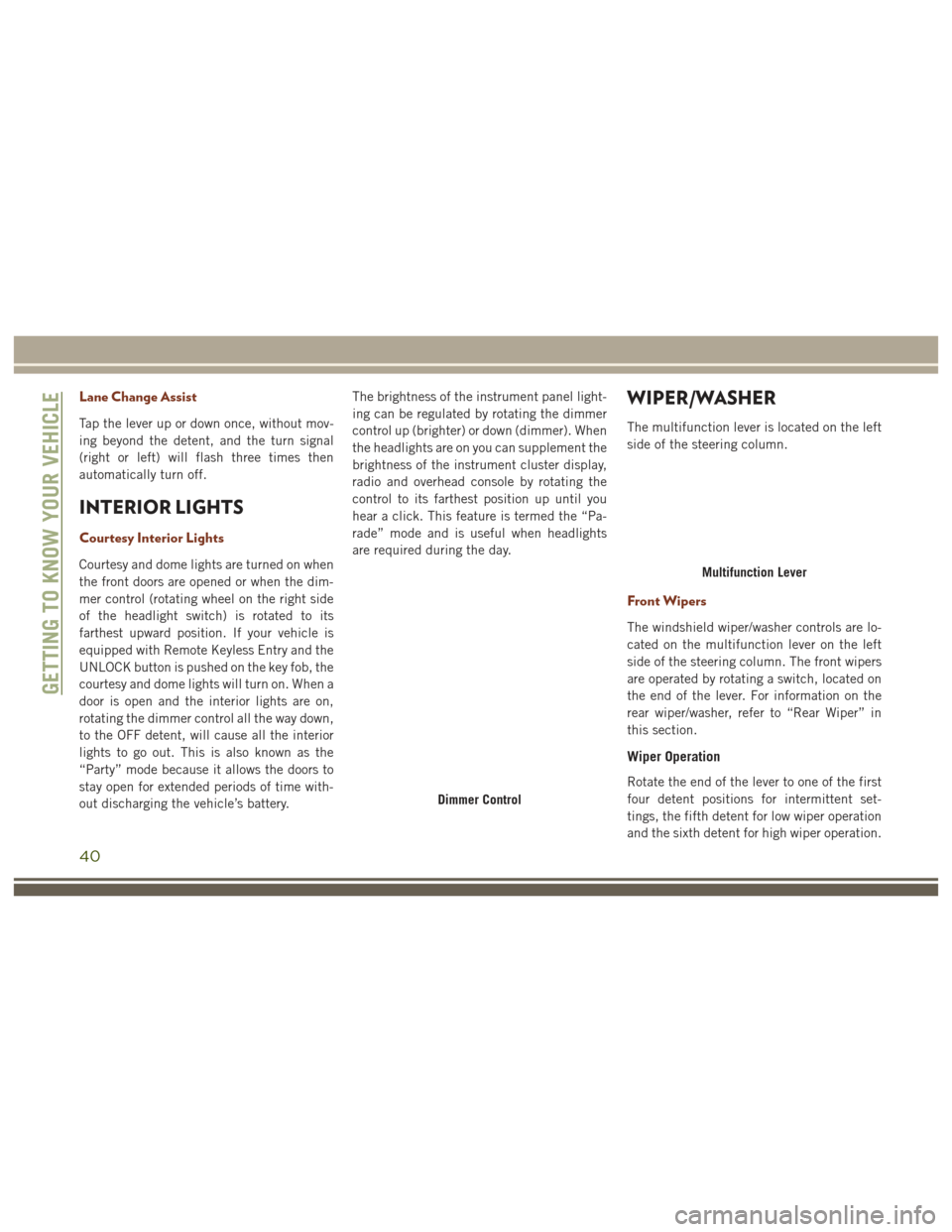
Dimmer Control
Multifunction Lever
GETTING TO KNOW YOUR VEHICLE
40
Page 55 of 372
WINDOWS
Power Windows
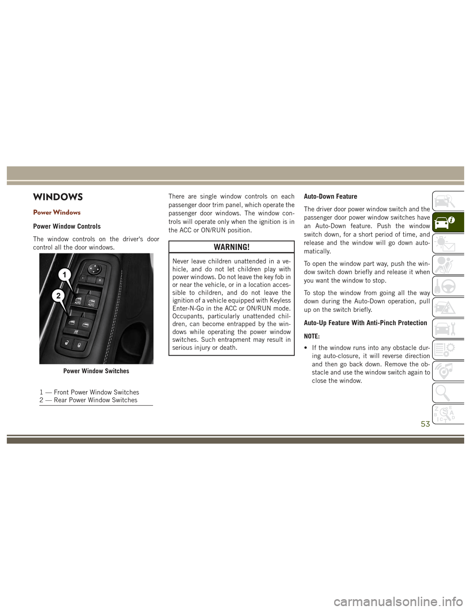
Power Window Controls
The window controls on the driver's door
control all the door windows.There are single window controls on each
passenger door trim panel, which operate the
passenger door windows. The window con-
trols will operate only when the ignition is in
the ACC or ON/RUN position.
WARNING!
Never leave children unattended in a ve-
hicle, and do not let children play with
power windows. Do not leave the key fob in
or near the vehicle, or in a location acces-
sible to children, and do not leave the
ignition of a vehicle equipped with Keyless
Enter-N-Go in the ACC or ON/RUN mode.
Occupants, particularly unattended chil-
dren, can become entrapped by the win-
dows while operating the power window
switches. Such entrapment may result in
serious injury or death.
Auto-Down Feature
The driver door power window switch and the
passenger door power window switches have
an Auto-Down feature. Push the window
switch down, for a short period of time, and
release and the window will go down auto-
matically.
To open the window part way, push the win-
dow switch down briefly and release it when
you want the window to stop.
To stop the window from going all the way
down during the Auto-Down operation, pull
up on the switch briefly.
Auto-Up Feature With Anti-Pinch Protection
NOTE:
• If the window runs into any obstacle dur-
ing auto-closure, it will reverse direction
and then go back down. Remove the ob-
stacle and use the window switch again to
close the window.
Power Window Switches
1 — Front Power Window Switches
2 — Rear Power Window Switches
53
Page 61 of 372
NOTE:
Use the power door lock switch on either front
door trim panel or the key fob to lock and
unlock the liftgate. The manual door locks on
the doors and the driver's door lock cylinder
will not lock and unlock the liftgate.
WARNING!
Driving with the liftgate open can allow
poisonous exhaust gases into your vehicle.
You and your passengers could be injured
by these fumes. Keep the liftgate closed
when you are operating the vehicle.
Closing
Grasp the liftgate closing handle and initiate
lowering the liftgate. Release the handle
when the liftgate takes over the closing effort.
NOTE:
Before closing the liftgate, make sure to be in
possession of the key because the liftgate
may be locked.
To Lock The Liftgate
With a valid Passive Entry key fob within 5 ft
(1.5 m) of the liftgate, pushing the Keyless
Enter-N-Go — Passive Entry lock button lo-
cated to the right of the outside handle re-
lease will lock the vehicle.
NOTE:
The liftgate unlock feature is built into the
electronic liftgate release.
Power Liftgate — If Equipped
The power liftgate may be
opened by pushing the
electronic liftgate release
(refer to “Keyless Enter-
N-Go — Passive Entry” lo-
cated in “Getting To Know
Your Vehicle”) or by push-
ing the liftgate button on the key fob. Push
the liftgate button on the key fob twice within
five seconds to open the power liftgate. Once
the liftgate is open, pushing the button twice
within five seconds a second time will close
the liftgate.
The power liftgate may also be opened or
closed by pushing the liftgate button located
on the front overhead console. If the liftgate
is fully open, the liftgate can be closed by
pushing the liftgate button located on the left
rear trim panel, near the liftgate opening. If
the liftgate is in motion, pushing the liftgate
button located on the left rear trim panel will
reverse the liftgate.
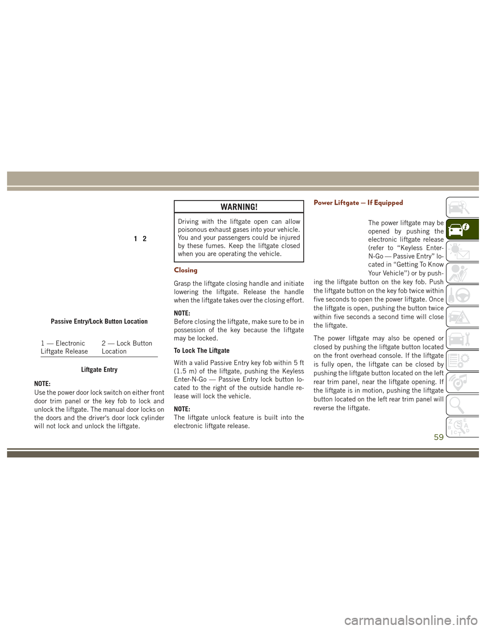
Passive Entry/Lock Button Location
1 — Electronic
Liftgate Release 2 — Lock Button
Location
Liftgate Entry
59
Page 149 of 372
STARTING AND OPERATING
STARTING PROCEDURES — GASO-
LINEENGINES..............149
Normal Starting...............149
Cold Weather Operation (Below –22°F Or
−30°C) ....................150
After Starting .................150
If Engine Fails To Start ..........150
After Starting .................150
STARTING PROCEDURES — DIESEL
ENGINES................. .150
Automatic Transmission..........151
Extreme Cold Weather ...........151
Normal Starting Procedure — Keyless
Enter-N-Go ..................152
Starting Fluids ................152
STOP/START SYSTEM — IF
EQUIPPED................ .153
Automatic Mode..............153
Possible Reasons The Engine Does Not
Autostop ...................153
To Start The Engine While In Autostop
Mode .....................154 To Manually Turn Off The Stop/Start
System
....................154
To Manually Turn On The Stop/Start
System ....................155
ENGINE BREAK-IN RECOMMENDA-
TIONS................... .155
3.6L & 5.7L Engines............155
Diesel Engines ................156
SRT Engines .................156
AUTOMATIC TRANSMISSION . . .157
Ignition Park Interlock ...........158
Brake/Transmission Shift Interlock
System ....................158
Fuel Economy (ECO) Mode ........158
Eight–Speed Automatic Transmission . .159
SPORT MODE — IF EQUIPPED . .161
FOUR WHEEL DRIVE
OPERATION............... .161
Quadra-Trac I Operating Instructions/
Precautions — If Equipped........161
Quadra-Trac II Operating Instructions/
Precautions — If Equipped ........162Shift Positions
................162
Shifting Procedures .............163
Quadra-Drive II System — If Equipped .165
QUADRA-LIFT — IF EQUIPPED . .166
Description .................166
Air Suspension Modes ...........168
Instrument Cluster Display Messages . .168
Operation ..................168
SELEC-TERRAIN — IF
EQUIPPED................ .170
Selec-Terrain Mode Selection.......170
Instrument Cluster Display Messages . .171
SELEC-TRACK — IF EQUIPPED
(SRT).................... .171
Custom....................171
Active Damping System ..........172
ELECTRONIC SPEED CONTROL .172
Activation...................173
Setting A Desired Speed .........173
Varying The Speed .............173
Resume Speed ...............174
STARTING AND OPERATING
147
Page 151 of 372
STARTING PROCEDURES —
GASOLINE ENGINES
Before starting your vehicle, adjust your seat,
adjust the inside and outside mirrors, fasten
your seat belt, and if present, instruct all
other occupants to buckle their seat belts.
WARNING!
• Before exiting a vehicle, always shift theautomatic transmission into PARK and
apply the parking brake. Always make
sure the keyless ignition node is in the
“OFF” mode, remove the key fob from
the vehicle and lock the vehicle.
• Never leave children alone in a vehicle,
or with access to an unlocked vehicle.
Leaving children in a vehicle unattended
is dangerous for a number of reasons. A
child or others could be seriously or
fatally injured. Children should be
warned not to touch the parking brake,
brake pedal or the gear selector.
• Do not leave the key fob in or near the
vehicle, or in a location accessible to
children, and do not leave the ignition of
WARNING!
a vehicle equipped with Keyless Enter-
N-Go in the ACC or ON/RUN mode. A
child could operate power windows,
other controls, or move the vehicle.
• Do not leave children or animals inside
parked vehicles in hot weather. Interior
heat build-up may cause serious injury
or death.
Normal Starting
To Turn On The Engine Using The ENGINE START/
STOP Button
1. The transmission must be in PARK or NEUTRAL.
2. Press and hold the brake pedal while pushing the ENGINE START/STOP button
once.
3. The system takes over and attempts to start the vehicle. If the vehicle fails to
start, the starter will disengage automati-
cally after 10 seconds.
4. If you wish to stop the cranking of the engine prior to the engine starting, push
the button again. NOTE:
Normal starting of either a cold or a warm
engine is obtained without pumping or press-
ing the accelerator pedal.
To Turn Off The Engine Using ENGINE START/
STOP Button
1. Place the gear selector in PARK, then
push and release the ENGINE START/
STOP button.
2. The ignition will return to the OFF mode.
3. If the gear selector is not in PARK, the ENGINE START/STOP button must be
held for two seconds or three short pushes
in a row with the vehicle speed above
5 mph (8 km/h) before the engine will
shut off. The ignition will remain in the
ACC mode until the gear selector is in
PARK and the button is pushed twice to
the OFF mode. If the gear selector is not in
PARK and the ENGINE START/STOP but-
ton is pushed once, the instrument cluster
will display a “Vehicle Not In Park” mes-
sage and the engine will remain running.
Never leave a vehicle out of the PARK
position, or it could roll.
149
Page 153 of 372
The starter is allowed to crank for up to
30-second intervals. Waiting a few minutes
between such intervals will protect the starter
from overheating.
WARNING!
• Before exiting a vehicle, always shift theautomatic transmission into PARK and
apply the parking brake. Always make
sure the keyless ignition node is in the
“OFF” mode, remove the key fob from
the vehicle and lock the vehicle.
• Never leave children alone in a vehicle,
or with access to an unlocked vehicle.
Leaving children in a vehicle unattended
is dangerous for a number of reasons. A
child or others could be seriously or
fatally injured. Children should be
warned not to touch the parking brake,
brake pedal or the gear selector.
• Do not leave the key fob in or near the
vehicle, or in a location accessible to
children, and do not leave the ignition of
a vehicle equipped with Keyless Enter-
N-Go in the ACC or ON/RUN mode. A
WARNING!
child could operate power windows,
other controls, or move the vehicle.
• Do not leave children or animals inside
parked vehicles in hot weather. Interior
heat build-up may cause serious injury
or death.
NOTE:
Engine start up in very low ambient tempera-
ture could result in evident white smoke. This
condition will disappear as the engine warms
up.
CAUTION!
• The engine is allowed to crank as long as 30 seconds. If the engine fails to start
during this period, please wait at least
two minutes for the starter to cool before
repeating start procedure.
• If the “Water in Fuel Indicator Light”
remains on, DO NOT START engine be-
fore you drain the water from the fuel
filters to avoid engine damage. Refer to
“Draining Fuel/Water Separator Filter”
CAUTION!
in “Servicing And Maintenance” for fur-
ther information.
Automatic Transmission
Start the engine with the transmission gear
selector in the PARK position. Apply the
brake before shifting to any driving range.
Extreme Cold Weather
The engine block heater is a resistance heater
installed in the water jacket of the engine. It
requires a 110–115 Volt AC electrical outlet
with a grounded, three-wire extension cord.
Its use is recommended for environments
that routinely fall below -10°F (-23°C). It
should be used when the vehicle has not been
running overnight or longer periods and
should be plugged in two hours prior to start.
Its use is required for cold starts with tem-
peratures under -20°F (-28°C).
151
Page 154 of 372
NOTE:
The engine block heater cord is a factory
installed option. If your vehicle is not
equipped, heater cords are available from
your authorized MOPAR dealer.
• A 12 Volt heater built into the fuel filterhousing aids in preventing fuel gelling. It is
controlled by a built-in thermostat.
• A Diesel Pre-Heat system both improves engine starting and reduces the amount of
white smoke generated by a warming
engine.
Normal Starting Procedure — Keyless
Enter-N-Go
Observe the instrument panel cluster lights
when starting the engine.
NOTE:
Normal starting of either a cold or a warm
engine is obtained without pumping or press-
ing the accelerator pedal
1. Always apply the parking brake.
2. Press and hold the brake pedal while pushing the ENGINE START/STOP button
once. NOTE:
A delay of the start of up to five seconds is
possible under very cold conditions. The
"Wait to Start" telltale will be illuminated
during the pre-heat process, When the
engine Wait To Start light goes off the
engine will automatically crank.
CAUTION!
If the “Water in Fuel Indicator Light” re-
mains on, DO NOT START the engine be-
fore you drain the water from the fuel
filters to avoid engine damage. Refer to
“Draining Fuel/Water Separator Filter” in
“Servicing And Maintenance” for further
information.
3. The system will automatically engage the starter to crank the engine. If the vehicle
fails to start, the starter will disengage
automatically after 25 seconds.
4. If you wish to stop the cranking of the engine prior to the engine starting, push
the button again.
5. Check that the oil pressure warning light has turned off. 6. Release the parking brake.
Starting Fluids
The engine is equipped with a glow plug
preheating system. If the instructions in this
manual are followed, the engine should start
in all conditions and no type of starting fluid
should be used.
WARNING!
• Do not leave children or animals inside
parked vehicles in hot weather. Interior
heat build up may cause serious injury
or death.
• When leaving the vehicle, always make
sure the keyless ignition node is in the
“OFF” mode, remove the key fob from
the vehicle and lock the vehicle.
• Never leave children alone in a vehicle,
or with access to an unlocked vehicle.
Allowing children to be in a vehicle un-
attended is dangerous for a number of
reasons. A child or others could be seri-
ously or fatally injured. Children should
be warned not to touch the parking
brake, brake pedal or the gear selector.
STARTING AND OPERATING
152
Page 155 of 372
WARNING!
• Do not leave the key fob in or near thevehicle, or in a location accessible to
children, and do not leave the ignition of
a vehicle equipped with Keyless Enter-
N-Go in the ACC or ON/RUN mode. A
child could operate power windows,
other controls, or move the vehicle.
STOP/START SYSTEM — IF
EQUIPPED
The Stop/Start function is developed to re-
duce fuel consumption. The system will stop
the engine automatically during a vehicle
stop if the required conditions are met. Re-
leasing the brake pedal or pressing the accel-
erator pedal will automatically re-start the
engine.
Automatic Mode
The Stop/Start feature is
enabled after every nor-
mal customer engine
start. At that time, the
system will go into STOP/
START READY and if all
other conditions are met,
can go into a STOP/START AUTOSTOP AC-
TIVE “Autostop” mode.
To Activate The Autostop Mode, The Following
Must Occur:
• The system must be in STOP/START READY state. A STOP/START READY mes-
sage will be displayed in the instrument
cluster display within the Stop/Start sec-
tion. Refer to “Instrument Cluster Dis-
play” in “Getting To Know Your Instrument
Panel” in your Owners Manual at
www.jeep.com/en/owners/manuals/ .
• The vehicle must be completely stopped.
• The shifter must be in a forward gear and the brake pedal depressed. The engine will shut down, the tachometer
will move to the zero position and the Stop/
Start telltale will illuminate indicating you
are in Autostop. Customer settings will be
maintained upon return to an engine running
condition.
Refer to the “Stop/Start System” in the
“Starting And Operating” section located in
your Owners Manual at
www.jeep.com/en/owners/manuals/ .
Possible Reasons The Engine Does Not
Autostop
Prior to engine shut down, the system will
check many safety and comfort conditions to
see if they are fulfilled. Detailed information
about the operation of the Stop/Start system
may be viewed in the instrument cluster dis-
play Stop/Start Screen. In the following situ-
ations, the engine will not stop:
• Driver’s seat belt is not buckled.
• Driver’s door is not closed.
• Battery temperature is too warm or cold.
• Battery charge is low.
• The vehicle is on a steep grade.
153
Page 214 of 372
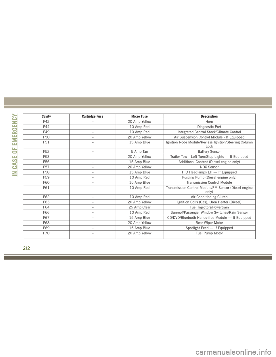
CavityCartridge Fuse Micro Fuse Description
F42 –20 Amp Yellow Horn
F44 –10 Amp Red Diagnostic Port
F49 –10 Amp Red Integrated Central Stack/Climate Control
F50 –20 Amp Yellow Air Suspension Control Module - If Equipped
F51 –15 Amp Blue Ignition Node Module/Keyless Ignition/Steering Column
Lock
F52 –5 Amp Tan Battery Sensor
F53 –20 Amp Yellow Trailer Tow – Left Turn/Stop Lights — If Equipped
F56 –15 Amp Blue Additional Content (Diesel engine only)
F57 –20 Amp Yellow NOX Sensor
F58 –15 Amp Blue HID Headlamps LH — If Equipped
F59 –10 Amp Red Purging Pump (Diesel engine only)
F60 –15 Amp Blue Transmission Control Module
F61 –10 Amp Red Transmission Control Module/PM Sensor (Diesel engine
only)
F62 –10 Amp Red Air Conditioning Clutch
F63 –20 Amp Yellow Ignition Coils (Gas), Urea Heater (Diesel)
F64 –25 Amp Clear Fuel Injectors/Powertrain
F66 –10 Amp Red Sunroof/Passenger Window Switches/Rain Sensor
F67 –15 Amp Blue CD/DVD/Bluetooth Hands-free Module — If Equipped
F68 –20 Amp Yellow Rear Wiper Motor
F69 –15 Amp Blue Spotlight Feed — If Equipped
F70 –20 Amp Yellow Fuel Pump Motor
IN CASE OF EMERGENCY
212
Page 364 of 372
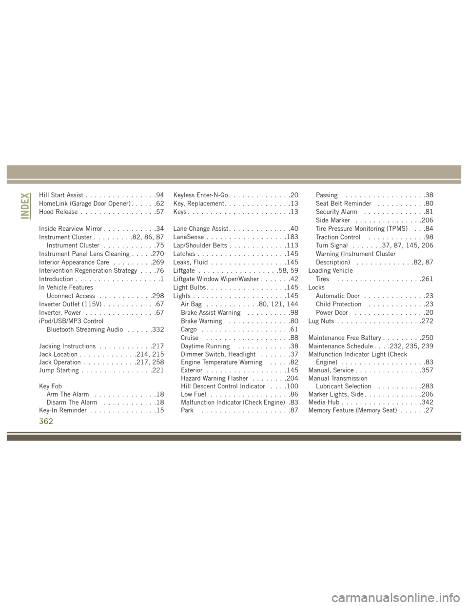
Hill Start Assist................94
HomeLink (Garage Door Opener) ......62
Hood Release .................57
Inside Rearview Mirror ............34
Instrument Cluster .........82, 86, 87
Instrument Cluster ............75
Instrument Panel Lens Cleaning .....270
Interior Appearance Care .........269
Intervention Regeneration Strategy ....76
Introduction ...................1
In Vehicle Features Uconnect Access ............298
Inverter Outlet (115V) ............67
Inverter, Power ................67
iPod/USB/MP3 Control Bluetooth Streaming Audio ......332
Jacking Instructions ............217
Jack Location .............214, 215
Jack Operation ............217, 258
Jump Starting ................221
Key Fob Arm The Alarm ..............18
Disarm The Alarm ............18
Key-In Reminder ...............15 Keyless Enter-N-Go
..............20
Key, Replacement ...............13
Keys .......................13
Lane Change Assist ..............40
LaneSense ..................183
Lap/Shoulder Belts .............113
Latches ....................145
Leaks, Fluid .................145
Liftgate ..................58, 59
Liftgate Window Wiper/Washer .......42
Light Bulbs ..................145
Lights .....................145
AirBag ............80, 121, 144
Brake Assist Warning ..........98
Brake Warning ..............80
Cargo ....................61
Cruise ...................88
Daytime Running ............38
Dimmer Switch, Headlight .......37
Engine Temperature Warning .....82
Exterior ..................145
Hazard
Warning Flasher ........204
Hill Descent Control Indicator . . . .100
Low Fuel ..................86
Malfunction Indicator (Check Engine) .83
Park ....................87 Passing
..................38
Seat Belt Reminder ...........80
Security Alarm ..............81
Side Marker ...............206
Tire Pressure Monitoring (TPMS) . . .84
Traction Control .............98
Turn Signal .......37, 87, 145, 206
Warning (Instrument Cluster
Description) .............82, 87
Loading Vehicle Tires ...................261
Locks Automatic Door ..............23
Child Protection .............23
Power Door ................20
Lug Nuts ...................272
Maintenance Free Battery .........250
Maintenance Schedule . . . .232, 235, 239
Malfunction Indicator Light (Check Engine) ...................83
Manual, Service ...............357
Manual Transmission Lubricant Selection ..........283
Marker Lights, Side .............206
Media Hub ..................342
Memory Feature (Memory Seat) ......27
INDEX
362