warning JEEP GRAND CHEROKEE 2017 WK2 / 4.G Owner's Manual
[x] Cancel search | Manufacturer: JEEP, Model Year: 2017, Model line: GRAND CHEROKEE, Model: JEEP GRAND CHEROKEE 2017 WK2 / 4.GPages: 372
Page 31 of 372
NOTE:
• Once a heat setting is selected, heat willbe felt within two to five minutes.
• The engine must be running for the heated seats to operate.
If the HI-level setting is selected, the system
will automatically switch to LO-level after
approximately 60 minutes of continuous op-
eration. At that time, the number of illumi-
nated LEDs changes from two to one, indicat-
ing the change. The LO-level setting will turn
OFF automatically after approximately
45 minutes.
Front Ventilated Seats
If your vehicle is equipped with ventilated
seats, the seat cushion and seat back will
have fans that draw the air from the passen-
ger compartment and move air through fine
perforations in the seat cover to help keep the
driver and front passenger cooler in higher
ambient temperatures. The fans operate at
two speeds, HI and LO. The front ventilated seats control buttons are
located within the Uconnect system. You can
gain access to the control buttons through
the climate screen or the controls screen.
• Press the ventilated seat button
once
to choose HI.
• Press the ventilated seat button
a
second time to choose LO.
• Press the ventilated seat button
a
third time to turn the ventilated seat OFF.
NOTE:
The engine must be running for the ventilated
seats to operate.
Vehicles Equipped With Remote Start
On models that are equipped with remote
start, the ventilated seats can be pro-
grammed to come on during a remote start.
This feature can be programmed through the
Uconnect system. Refer to your Owner's
Manual at
www.jeep.com/en/owners/manuals/ for fur-
ther details.
HEAD RESTRAINTS
Head restraints are designed to reduce the
risk of injury by restricting head movement in
the event of a rear impact. Head restraints
should be adjusted so that the top of the head
restraint is located above the top of your ear.
WARNING!
• All occupants, including the driver, should not operate a vehicle or sit in a
vehicle’s seat until the head restraints
are placed in their proper positions in
order to minimize the risk of neck injury
in the event of a crash.
• Head restraints should never be ad-
justed while the vehicle is in motion.
Driving a vehicle with the head restraints
improperly adjusted or removed could
cause serious injury or death in the event
of a collision.
29
Page 33 of 372
NOTE:
• The head restraints should only be re-moved by qualified technicians, for ser-
vice purposes only. If either of the head
restraints require removal, see your autho-
rized dealer.
• In the event of deployment of an Active Head Restraint, refer to “Occupant Re-
straint Systems” in “Safety” in your Own-
er’s Manual at www.jeep.com/en/
owners/manuals/ for further information.
WARNING!
• All occupants, including the driver,
should not operate a vehicle or sit in a
vehicle’s seat until the head restraints
are placed in their proper positions in
order to minimize the risk of neck injury
in the event of a collision.
• Do not place items over the top of the
Active Head Restraint, such as coats,
seat covers or portable DVD players.
These items may interfere with the op-
eration of the Active Head Restraint in
the event of a collision and could result
in serious injury or death.
• Active Head Restraints may be deployed
if they are struck by an object such as a
hand, foot or loose cargo. To avoid acci-
dental deployment of the Active Head
Restraint ensure that all cargo is se-
cured, as loose cargo could contact the
Active Head Restraint during sudden
stops. Failure to follow this warning
could cause personal injury if the Active
Head Restraint is deployed.
Front Removal
NOTE:
• The head restraints should only be re- moved by qualified technicians, for ser-
vice purposes only. If either of the head
restraints require removal, see your autho-
rized dealer.
• In the event of deployment of an Active Head Restraint, refer to “Occupant Re-
straint Systems” in “Safety” in your Own-
er’s Manual at www.jeep.com/en/
owners/manuals/ for further information.
WARNING!
• All occupants, including the driver,
should not operate a vehicle or sit in a
vehicle’s seat until the head restraints
are placed in their proper positions in
order to minimize the risk of neck injury
in the event of a collision.
• Do not place items over the top of the
Active Head Restraint, such as coats,
seat covers or portable DVD players.
These items may interfere with the op-
eration of the Active Head Restraint in
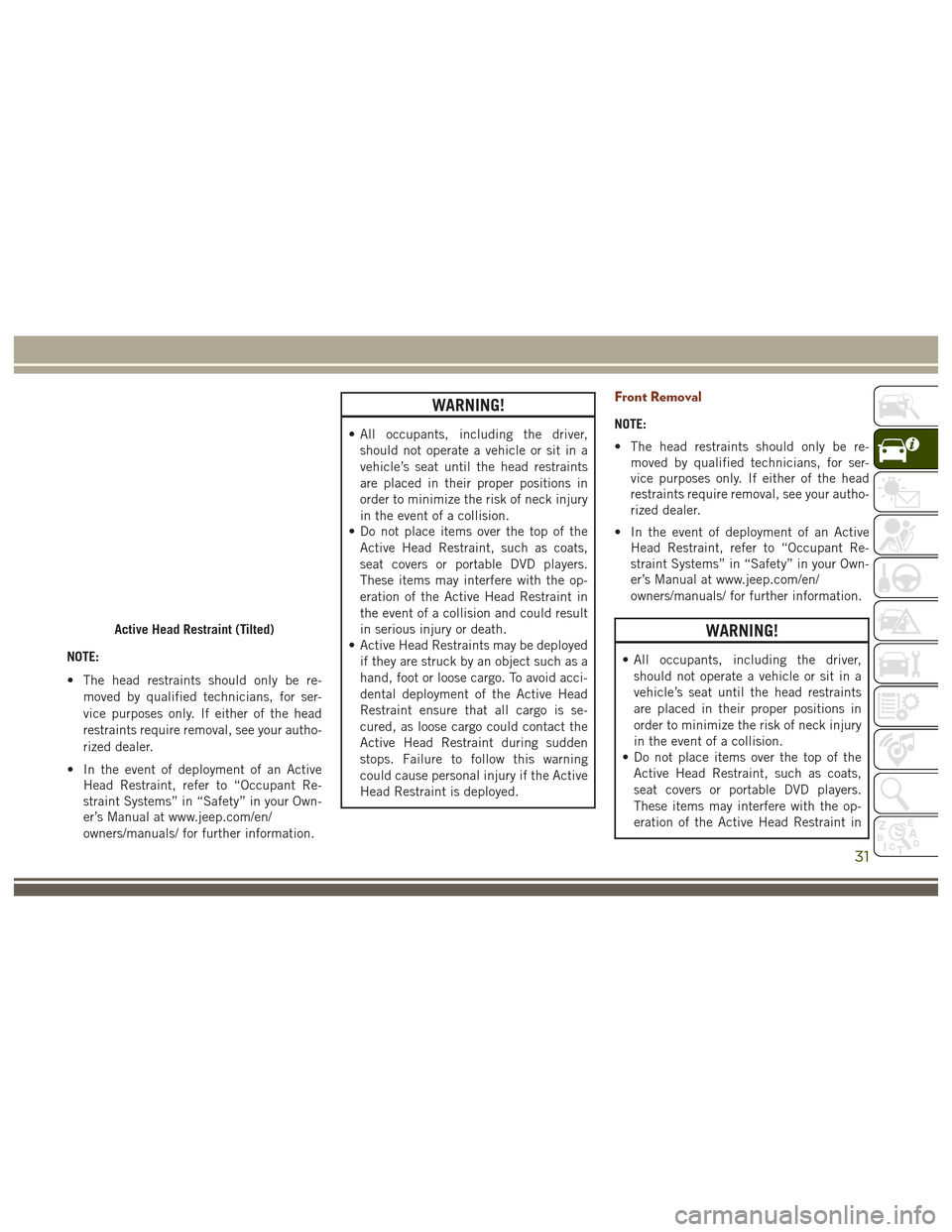
Active Head Restraint (Tilted)
31
Page 34 of 372
WARNING!
the event of a collision and could result
in serious injury or death.
• Active Head Restraints may be deployed
if they are struck by an object such as a
hand, foot or loose cargo. To avoid acci-
dental deployment of the Active Head
Restraint ensure that all cargo is se-
cured, as loose cargo could contact the
Active Head Restraint during sudden
stops. Failure to follow this warning
could cause personal injury if the Active
Head Restraint is deployed.
Rear Adjustment
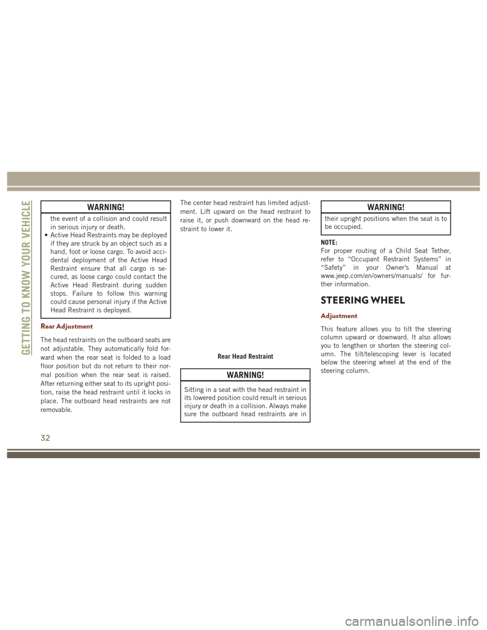
The head restraints on the outboard seats are
not adjustable. They automatically fold for-
ward when the rear seat is folded to a load
floor position but do not return to their nor-
mal position when the rear seat is raised.
After returning either seat to its upright posi-
tion, raise the head restraint until it locks in
place. The outboard head restraints are not
removable. The center head restraint has limited adjust-
ment. Lift upward on the head restraint to
raise it, or push downward on the head re-
straint to lower it.
WARNING!
Sitting in a seat with the head restraint in
its lowered position could result in serious
injury or death in a collision. Always make
sure the outboard head restraints are in
WARNING!
their upright positions when the seat is to
be occupied.
NOTE:
For proper routing of a Child Seat Tether,
refer to “Occupant Restraint Systems” in
“Safety” in your Owner’s Manual at
www.jeep.com/en/owners/manuals/ for fur-
ther information.
STEERING WHEEL
Adjustment
This feature allows you to tilt the steering
column upward or downward. It also allows
you to lengthen or shorten the steering col-
umn. The tilt/telescoping lever is located
below the steering wheel at the end of the
steering column.
Rear Head RestraintGETTING TO KNOW YOUR VEHICLE
32
Page 35 of 372
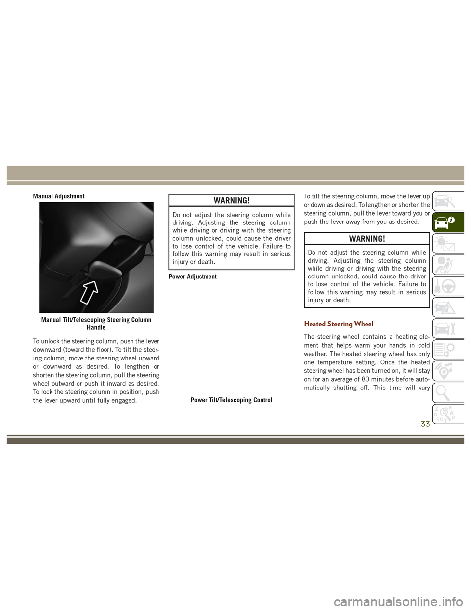
Manual Adjustment
To unlock the steering column, push the lever
downward (toward the floor). To tilt the steer-
ing column, move the steering wheel upward
or downward as desired. To lengthen or
shorten the steering column, pull the steering
wheel outward or push it inward as desired.
To lock the steering column in position, push
the lever upward until fully engaged.WARNING!
Do not adjust the steering column while
driving. Adjusting the steering column
while driving or driving with the steering
column unlocked, could cause the driver
to lose control of the vehicle. Failure to
follow this warning may result in serious
injury or death.
Power Adjustment To tilt the steering column, move the lever up
or down as desired. To lengthen or shorten the
steering column, pull the lever toward you or
push the lever away from you as desired.
WARNING!
Do not adjust the steering column while
driving. Adjusting the steering column
while driving or driving with the steering
column unlocked, could cause the driver
to lose control of the vehicle. Failure to
follow this warning may result in serious
injury or death.
Heated Steering Wheel
The steering wheel contains a heating ele-
ment that helps warm your hands in cold
weather. The heated steering wheel has only
one temperature setting. Once the heated
steering wheel has been turned on, it will stay
on for an average of 80 minutes before auto-
matically shutting off. This time will vary
Manual Tilt/Telescoping Steering Column
Handle
Power Tilt/Telescoping Control
33
Page 36 of 372
based on environmental temperatures. The
heated steering wheel can shut off early or
may not turn on when the steering wheel is
already warm.
The heated steering wheel control button is
located within the Uconnect system. You can
gain access to the control button through the
climate screen or the controls screen.
• Press the heated steering wheel button
once to turn the heating element ON.
• Press the heated steering wheel button
a second time to turn the heating
element OFF.
NOTE:
The engine must be running for the heated
steering wheel to operate.
Vehicles Equipped With Remote Start
On models that are equipped with remote
start, the heated steering wheel can be pro-
grammed to come on during a remote start
through the Uconnect system. Refer to
“Uconnect Settings” in “Multimedia” in the
Owner’s Manualat
www.jeep.com/en/owners/manuals/ for fur-
ther information.
WARNING!
• Persons who are unable to feel pain to the skin because of advanced age,
chronic illness, diabetes, spinal cord in-
jury, medication, alcohol use, exhaus-
tion, or other physical conditions must
exercise care when using the steering
wheel heater. It may cause burns even at
low temperatures, especially if used for
long periods.
• Do not place anything on the steering
wheel that insulates against heat, such
as a blanket or steering wheel covers of
any type and material. This may cause
the steering wheel heater to overheat.
MIRRORS
Interior Mirror
Manual Mirror
The mirror head can be adjusted up, down,
left, and right for various drivers. The mirror
should be adjusted to center on the view
through the rear window. Headlight glare from vehicles behind you can
be reduced by moving the small control under
the mirror to the night position (toward the
rear of the vehicle). The mirror should be
adjusted while set in the day position (toward
the windshield).
Electrochromatic Mirror
The mirror head can be adjusted up, down,
left, and right for various drivers. The mirror
should be adjusted to center on the view
through the rear window.
This mirror automatically adjusts for head-
light glare from vehicles behind you.
Adjusting Rearview Mirror
GETTING TO KNOW YOUR VEHICLE
34
Page 55 of 372
WINDOWS
Power Windows
Power Window Controls
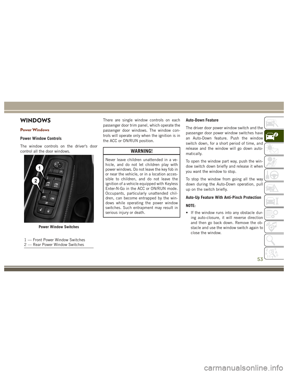
The window controls on the driver's door
control all the door windows.There are single window controls on each
passenger door trim panel, which operate the
passenger door windows. The window con-
trols will operate only when the ignition is in
the ACC or ON/RUN position.
WARNING!
Never leave children unattended in a ve-
hicle, and do not let children play with
power windows. Do not leave the key fob in
or near the vehicle, or in a location acces-
sible to children, and do not leave the
ignition of a vehicle equipped with Keyless
Enter-N-Go in the ACC or ON/RUN mode.
Occupants, particularly unattended chil-
dren, can become entrapped by the win-
dows while operating the power window
switches. Such entrapment may result in
serious injury or death.
Auto-Down Feature
The driver door power window switch and the
passenger door power window switches have
an Auto-Down feature. Push the window
switch down, for a short period of time, and
release and the window will go down auto-
matically.
To open the window part way, push the win-
dow switch down briefly and release it when
you want the window to stop.
To stop the window from going all the way
down during the Auto-Down operation, pull
up on the switch briefly.
Auto-Up Feature With Anti-Pinch Protection
NOTE:
• If the window runs into any obstacle dur-
ing auto-closure, it will reverse direction
and then go back down. Remove the ob-
stacle and use the window switch again to
close the window.
Power Window Switches
1 — Front Power Window Switches
2 — Rear Power Window Switches
53
Page 56 of 372
• Any impact due to rough road conditionsmay trigger the auto-reverse function un-
expectedly during auto-closure. If this
happens, pull the switch lightly to the first
detent and hold to close the window
manually.
WARNING!
There is no anti-pinch protection when the
window is almost closed. To avoid personal
injury be sure to clear your arms, hands,
fingers and all objects from the window
path before closing.
Reset Auto-Up
Should the Auto-Up feature stop working, the
window probably needs to be reset. To reset
Auto-Up:
1. Pull the window switch up to close the
window completely and continue to hold
the switch up for an additional two sec-
onds after the window is closed. 2. Push the window switch down firmly to
open the window completely and continue
to hold the switch down for an additional
two seconds after the window is fully
open.
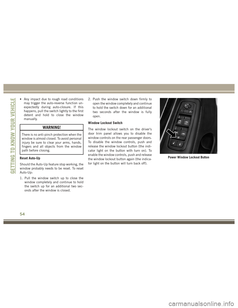
Window Lockout Switch
The window lockout switch on the driver's
door trim panel allows you to disable the
window controls on the rear passenger doors.
To disable the window controls, push and
release the window lockout button (the indi-
cator light on the button with turn on). To
enable the window controls, push and release
the window lockout button again (the indica-
tor light on the button will turn back off).
Power Window Lockout Button
GETTING TO KNOW YOUR VEHICLE
54
Page 58 of 372
Closing
Express Closing
Push the switch forward and release it within
one-half second. The sunroof will fully close
automatically from any position.
Manual Closing
Push and hold the switch forward to close the
sunroof. Any release of the switch will stop
the movement, and the sunroof will remain in
a partially closed position until the switch is
pushed again.
Wind Buffeting
Wind buffeting can be described as a
helicopter-type percussion sound. If buffet-
ing occurs with the rear windows open, adjust
the front and rear windows together.
If buffeting occurs with the sunroof open,
adjust the sunroof opening, or adjust any
window. This will minimize buffeting.
Anti-Pinch Safety Device
This feature will detect an obstruction in the
opening of the sunroof during Express Close
operation. If an obstruction in the path of the
sunroof is detected, the sunroof will auto-
matically retract. Remove the obstruction if
this occurs. Next, push the switch forward
and release to Express Close.
NOTE:
If three consecutive sunroof close attempts
result in Pinch Protect reversals, the fourth
close attempt will be a Manual Close move-
ment with Pinch Protect disabled.
WARNING!
• Do not let children play with the sunroof.Never leave children unattended in a
vehicle, or with access to an unlocked
vehicle. Do not leave the key fob in or
near the vehicle, and do not leave the
ignition of a vehicle equipped with Key-
less Enter-N-Go in the ACC or ON/RUN
mode. Occupants, particularly unat-
tended children, can become entrapped
by the power sunroof while operating the
WARNING!
power sunroof switch. Such entrapment
may result in serious injury or death.
• In a collision, there is a greater risk of
being thrown from a vehicle with an
open sunroof. You could also be severely
injured or killed. Always fasten your seat
belt properly and make sure all passen-
gers are properly secured.
• Do not allow small children to operate
the sunroof. Never allow your fingers,
other body parts, or any object to project
through the sunroof opening. Injury may
result.
COMMANDVIEW SUNROOF
WITH POWER SHADE
The CommandView sunroof with power shade
switch is located on the overhead console.
GETTING TO KNOW YOUR VEHICLE
56
Page 60 of 372
WARNING!
Be sure the hood is fully latched before
driving your vehicle. If the hood is not fully
latched, it could open when the vehicle is
in motion and block your vision. Failure to
follow this warning could result in serious
injury or death.
Closing
1. Before closing the hood, check to makesure all filler caps are correctly installed.
2. Lower the hood halfway and push down to close the hood and securely latch it into
place.
WARNING!
Be sure the hood is fully latched before
driving your vehicle. If the hood is not fully
latched, it could open when the vehicle is
in motion and block your vision. Failure to
follow this warning could result in serious
injury or death.
CAUTION!
To prevent possible damage, do not slam
the hood to close it. Use a firm downward
push at the front center of the hood to
ensure that both latches engage.
LIFTGATE
Opening
The liftgate can be opened from inside the
vehicle using the Power Liftgate button on
the overhead console, using the key fob out-
side of the vehicle or the Electronic Liftgate
Release.
To Unlock/Enter The Liftgate
The liftgate may be released in several ways:
• Key fob
• Outside handle
• Button on Overhead Console The liftgate passive entry unlock feature is
built into the electronic liftgate release. With
a valid Passive Entry Key Fob within 5 ft
(1.5 m) of the liftgate, push the electronic
liftgate release to open with one fluid motion.
Push the button on the key fob twice within
five seconds to release the liftgate.
NOTE:
If “Unlock All Doors 1st Press” is pro-
grammed in the instrument cluster display,
all doors will unlock when you push the
electronic release on the liftgate. If "Unlock
Driver Door 1st Press" is programmed in
Uconnect, the liftgate will unlock when you
push the electronic release on the liftgate.
Refer to “Uconnect Settings” in “Multime-
dia” for further information.
GETTING TO KNOW YOUR VEHICLE
58
Page 61 of 372
NOTE:
Use the power door lock switch on either front
door trim panel or the key fob to lock and
unlock the liftgate. The manual door locks on
the doors and the driver's door lock cylinder
will not lock and unlock the liftgate.
WARNING!
Driving with the liftgate open can allow
poisonous exhaust gases into your vehicle.
You and your passengers could be injured
by these fumes. Keep the liftgate closed
when you are operating the vehicle.
Closing
Grasp the liftgate closing handle and initiate
lowering the liftgate. Release the handle
when the liftgate takes over the closing effort.
NOTE:
Before closing the liftgate, make sure to be in
possession of the key because the liftgate
may be locked.
To Lock The Liftgate
With a valid Passive Entry key fob within 5 ft
(1.5 m) of the liftgate, pushing the Keyless
Enter-N-Go — Passive Entry lock button lo-
cated to the right of the outside handle re-
lease will lock the vehicle.
NOTE:
The liftgate unlock feature is built into the
electronic liftgate release.
Power Liftgate — If Equipped
The power liftgate may be
opened by pushing the
electronic liftgate release
(refer to “Keyless Enter-
N-Go — Passive Entry” lo-
cated in “Getting To Know
Your Vehicle”) or by push-
ing the liftgate button on the key fob. Push
the liftgate button on the key fob twice within
five seconds to open the power liftgate. Once
the liftgate is open, pushing the button twice
within five seconds a second time will close
the liftgate.
The power liftgate may also be opened or
closed by pushing the liftgate button located
on the front overhead console. If the liftgate
is fully open, the liftgate can be closed by
pushing the liftgate button located on the left
rear trim panel, near the liftgate opening. If
the liftgate is in motion, pushing the liftgate
button located on the left rear trim panel will
reverse the liftgate.
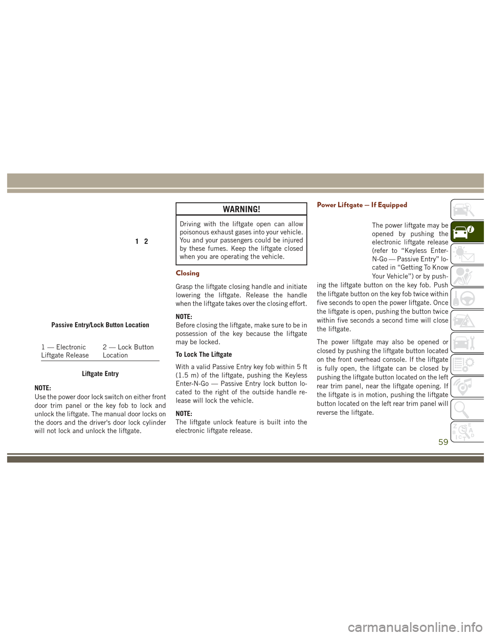
Passive Entry/Lock Button Location
1 — Electronic
Liftgate Release 2 — Lock Button
Location
Liftgate Entry
59