warning JEEP GRAND CHEROKEE 2017 WK2 / 4.G Owner's Manual
[x] Cancel search | Manufacturer: JEEP, Model Year: 2017, Model line: GRAND CHEROKEE, Model: JEEP GRAND CHEROKEE 2017 WK2 / 4.GPages: 372
Page 62 of 372
When the liftgate button on the key fob is
pushed two times, the turn signals will flash
twice to signal that the liftgate is opening or
closing (if Flash Lamps with Lock is enabled in
the Uconnect settings), and the liftgate chime
will be audible. Refer to "Uconnect Settings" in
"Multimedia” for further information.
NOTE:
• In the event of a power malfunction to theliftgate, an emergency liftgate latch re-
lease can be used to open the liftgate. The
emergency liftgate latch release can be
accessed through a snap-in cover located
on the liftgate trim panel.
• If liftgate is left open for an extended period of time, the liftgate may need to be
closed manually to reset power liftgate
functionality.
WARNING!
During power operation, personal injury or
cargo damage may occur. Ensure the lift-
gate travel path is clear. Make sure the
liftgate is closed and latched before driv-
ing away. NOTE:
• The power liftgate buttons will not operate
if the vehicle is in gear or the vehicle
speed is above 0 MPH (0 km/h).
• The power liftgate will not operate in tem- peratures below −22°F (−30°C) or tem-
peratures above 150° F (65° C). Be sure to
remove any buildup of snow or ice from the
liftgate before pushing any of the power
liftgate switches.
• If anything obstructs the power liftgate while it is closing or opening, the liftgate
will automatically reverse to the closed or
open position, provided it meets sufficient
resistance.
• There are also pinch sensors attached to the side of the liftgate. Light pressure
anywhere along these strips will cause the
liftgate to return to the open position.
• If the liftgate is not fully open, push the liftgate button on the key fob twice to
operate the liftgate.
• If the electronic liftgate release is pushed while the power liftgate is closing, the
liftgate will reverse to the full open posi-
tion. • If the electronic liftgate release is pushed
while the power liftgate is opening, the
liftgate motor will disengage to allow
manual operation.
• If the power liftgate encounters multiple obstructions within the same cycle, the
system will automatically stop and the
liftgate must be opened or closed
manually.
WARNING!
• Driving with the liftgate open can allowpoisonous exhaust gases into your ve-
hicle. You and your passengers could be
injured by these fumes. Keep the liftgate
closed when you are operating the ve-
hicle.
• If you are required to drive with the
liftgate open, make sure that all win-
dows are closed, and the climate control
blower switch is set at high speed. Do
not use the recirculation mode.
GETTING TO KNOW YOUR VEHICLE
60
Page 63 of 372
Cargo Area Features
Rechargeable Flashlight
The rechargeable flashlight is mounted on
the left side of the cargo area. The flashlight
snaps out of the bezel when needed. The
flashlight features two bright LED light bulbs
and is powered by rechargeable lithium bat-
teries that recharge when snapped back into
place.
Push in on the flashlight to release it.
To operate the flashlight, push the switch
once for high, twice for low, and a third time
to return to off.
Cargo Storage Bins
There are up to four removable storage bins
located in the rear cargo area. There are two
storage bins located on either side of the
cargo area.
NOTE:
If your vehicle is equipped with a rear sub-
woofer, the passenger side cargo area will not
be available.Two additional storage bins are located under
the load floor. To access the lower storage
bins, raise the load floor and attach the tether
strap (attached to the bottom of the load
floor) to the liftgate opening.
Retractable Cargo Area Cover — If
Equipped
NOTE:
The purpose of this cover is for privacy, not to
secure loads. It will not prevent cargo from
shifting or protect passengers from loose
cargo.
To cover the cargo area:
1. Grasp the cover at the center handle. Pull
it over the cargo area.
2. Insert the pins on the ends of the cover into the slots in the pillar trim cover.
3. The liftgate may be opened with the cargo cover in place.
WARNING!
In a collision, a loose cargo cover in the
vehicle could cause injury. It could fly
WARNING!
around in a sudden stop and strike some-
one in the vehicle. Do not store the cargo
cover on the cargo floor or in the passenger
compartment. Remove the cover from the
vehicle when taken from its mounting. Do
not store it in the vehicle.
Rear Cargo Tie-Downs
The rear cargo tie-downs, located on the
cargo area floor, should be used to safely
secure loads when the vehicle is moving.
WARNING!
• To help protect against personal injury,passengers should not be seated in the
rear cargo area. The rear cargo space is
intended for load carrying purposes only,
not for passengers, who should sit in
seats and use seat belts.
• Cargo tie-down hooks are not safe an-
chors for a child seat tether strap. In a
sudden stop or accident, a hook could
pull loose and allow the child seat to
come loose. A child could be badly in-
61
Page 64 of 372
WARNING!
jured. Use only the anchors provided for
child seat tethers.
The weight and position of cargo and pas-
sengers can change the vehicle center of
gravity and vehicle handling. To avoid loss
of control resulting in personal injury, fol-
low these guidelines for loading your ve-
hicle:
• Do not carry loads which exceed the load
limits described on the label attached to
the left door or left door center pillar.
• Always place cargo evenly on the cargo
floor. Put heavier objects as low and as
far forward as possible.
• Place as much cargo as possible in front
of the rear axle. Too much weight or
improperly placed weight over or behind
the rear axle can cause the rear of the
vehicle to sway.
• Do not pile luggage or cargo higher than
the top of the seatback. This could im-
pair visibility or become a dangerous
projectile in a sudden stop or accident.
UNIVERSAL GARAGE DOOR
OPENER (HomeLink)
• HomeLink replaces up to three hand-held
transmitters that operate devices such as
garage door openers, motorized gates,
lighting or home security systems. The
HomeLink unit is powered by your vehicles
12 Volt battery. • The HomeLink buttons that are located in
the overhead console or sunvisor desig-
nate the three different HomeLink chan-
nels.
• The HomeLink indicator is located above the center button.
Before You Begin Programming
HomeLink
Ensure that your vehicle is parked outside of
the garage before you begin programming.
For efficient programming and accurate
transmission of the radio-frequency signal, it
is recommended that a new battery be placed
in the hand-held transmitter of the device
that is being programmed to the HomeLink
system.
To erase the channels, place the ignition
switch into the ON/RUN position, then push
and hold the two outside HomeLink buttons
(I and III) for up to 20 seconds or until the red
indicator flashes.
Universal Garage Door Opener (HomeLink)GETTING TO KNOW YOUR VEHICLE
62
Page 66 of 372
3. Push and hold the HomeLink button youwant to program while you push and hold
the hand-held transmitter button.
4. Continue to hold both buttons and ob- serve the indicator light. The HomeLink
indicator will flash slowly and then rapidly
after HomeLink has received the fre-
quency signal from the hand-held trans-
mitter. Release both buttons after the
indicator light changes from slow to rapid.
5. Push and hold the programmed HomeLink button and observe the indica-
tor light. If the indicator light stays on
constantly, programming is complete and
the garage door (or device) should activate
when the HomeLink button is pushed.
6. To program the two remaining HomeLink buttons, repeat each step for each re-
maining button. DO NOT erase the
channels.Using HomeLink
To operate, push and release the pro-
grammed HomeLink button. Activation will
now occur for the programmed device (i.e.,
garage door opener, gate operator, security
system, entry door lock, home/office lighting,
etc.). The hand-held transmitter of the device
may also be used at any time.
WARNING!
• Your motorized door or gate will openand close while you are programming
the universal transceiver. Do not pro-
gram the transceiver if people or pets are
in the path of the door or gate.
• Do not run your vehicle in a closed
garage or confined area while program-
ming the transceiver. Exhaust gas from
your vehicle contains Carbon Monoxide
(CO) which is odorless and colorless.
Carbon Monoxide is poisonous when in-
haled and can cause you and others to
be severely injured or killed.
INTERNAL EQUIPMENT
Power Outlets
There are three 12 Volt electrical power out-
lets on this vehicle.
The front power outlet is located inside the
center storage bin of the instrument panel.
Push inward on the storage lid to open the
compartment and gain access to this power
outlet.
Front Power Outlet
GETTING TO KNOW YOUR VEHICLE
64
Page 69 of 372
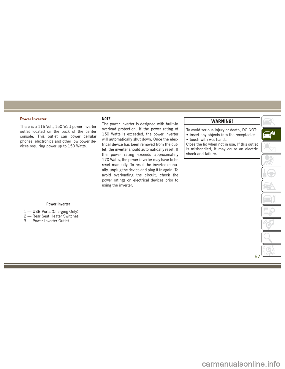
Power Inverter
There is a 115 Volt, 150 Watt power inverter
outlet located on the back of the center
console. This outlet can power cellular
phones, electronics and other low power de-
vices requiring power up to 150 Watts.NOTE:
The power inverter is designed with built-in
overload protection. If the power rating of
150 Watts is exceeded, the power inverter
will automatically shut down. Once the elec-
trical device has been removed from the out-
let, the inverter should automatically reset. If
the power rating exceeds approximately
170 Watts, the power inverter may have to be
reset manually. To reset the inverter manu-
ally, unplug the device and plug it in again. To
avoid overloading the circuit, check the
power ratings on electrical devices prior to
using the inverter.
WARNING!
To avoid serious injury or death, DO NOT:
• insert any objects into the receptacles
• touch with wet hands
Close the lid when not in use. If this outlet
is mishandled, it may cause an electric
shock and failure.
Power Inverter
1 — USB Ports (Charging Only)
2 — Rear Seat Heater Switches
3 — Power Inverter Outlet
67
Page 71 of 372
GETTING TO KNOW YOUR INSTRUMENT PANEL
INSTRUMENT CLUSTER.......70
Instrument Cluster Descriptions ......73
INSTRUMENT CLUSTER
DISPLAY...................74
Instrument Cluster Display Location and
Controls....................74
Oil Change Reset ...............75
Instrument Cluster Display Selectable
Items ......................75
SRT Performance Features .........76Diesel Particulate Filter (DPF)
Messages
...................76
Diesel Exhaust Fluid (DEF) Warning
Messages ....................78
Diesel Exhaust Fluid (DEF) Fault Warning
Messages ....................78
TRIPCOMPUTER.............80
WARNING/INDICATOR LIGHTS AND
MESSAGES.................80
Red Telltale Lights ..............80 Yellow Telltale Lights
.............83
Blue Telltale Lights ..............87
Green Telltale Lights .............87
White Telltale Lights .............88
ONBOARD DIAGNOSTIC SYSTEM —
OBDII ....................89
Onboard Diagnostic System (OBD II)
Cybersecurity.................89
GETTING TO KNOW YOUR INSTRUMENT PANEL
69
Page 75 of 372
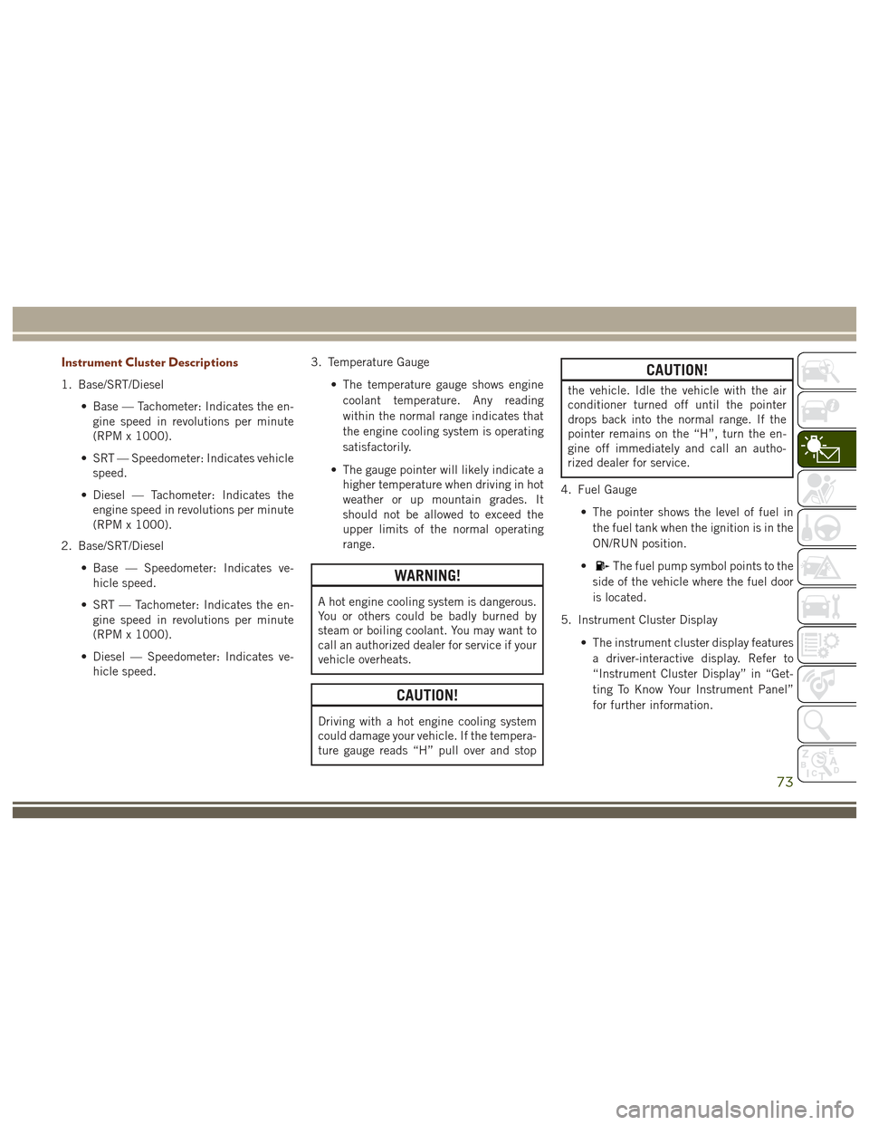
Instrument Cluster Descriptions
1. Base/SRT/Diesel• Base — Tachometer: Indicates the en-gine speed in revolutions per minute
(RPM x 1000).
• SRT — Speedometer: Indicates vehicle speed.
• Diesel — Tachometer: Indicates the engine speed in revolutions per minute
(RPM x 1000).
2. Base/SRT/Diesel
• Base — Speedometer: Indicates ve-hicle speed.
• SRT — Tachometer: Indicates the en- gine speed in revolutions per minute
(RPM x 1000).
• Diesel — Speedometer: Indicates ve- hicle speed. 3. Temperature Gauge
• The temperature gauge shows enginecoolant temperature. Any reading
within the normal range indicates that
the engine cooling system is operating
satisfactorily.
• The gauge pointer will likely indicate a higher temperature when driving in hot
weather or up mountain grades. It
should not be allowed to exceed the
upper limits of the normal operating
range.
WARNING!
A hot engine cooling system is dangerous.
You or others could be badly burned by
steam or boiling coolant. You may want to
call an authorized dealer for service if your
vehicle overheats.
CAUTION!
Driving with a hot engine cooling system
could damage your vehicle. If the tempera-
ture gauge reads “H” pull over and stop
CAUTION!
the vehicle. Idle the vehicle with the air
conditioner turned off until the pointer
drops back into the normal range. If the
pointer remains on the “H”, turn the en-
gine off immediately and call an autho-
rized dealer for service.
4. Fuel Gauge • The pointer shows the level of fuel inthe fuel tank when the ignition is in the
ON/RUN position.
•
The fuel pump symbol points to the
side of the vehicle where the fuel door
is located.
5. Instrument Cluster Display • The instrument cluster display featuresa driver-interactive display. Refer to
“Instrument Cluster Display” in “Get-
ting To Know Your Instrument Panel”
for further information.
73
Page 76 of 372
INSTRUMENT CLUSTER
DISPLAY
Your vehicle may be equipped with an instru-
ment cluster display, which offers useful in-
formation to the driver. With the ignition in
the STOP/OFF position (and the key removed,
for vehicles with mechanical key), opening/
closing of a door will activate the display for
viewing, and display the total miles or kilo-
meters in the odometer. Your instrument
cluster display is designed to display impor-
tant information about your vehicle’s systems
and features. Using a driver interactive dis-
play located on the instrument panel, your
instrument cluster display can show you how
systems are working and give you warnings
when they aren’t. The steering wheel
mounted controls allow you to scroll through
and enter the main menus and submenus.
You can access the specific information you
want and make selections and adjustments.
Instrument Cluster Display Location and
Controls
The instrument cluster display is located in
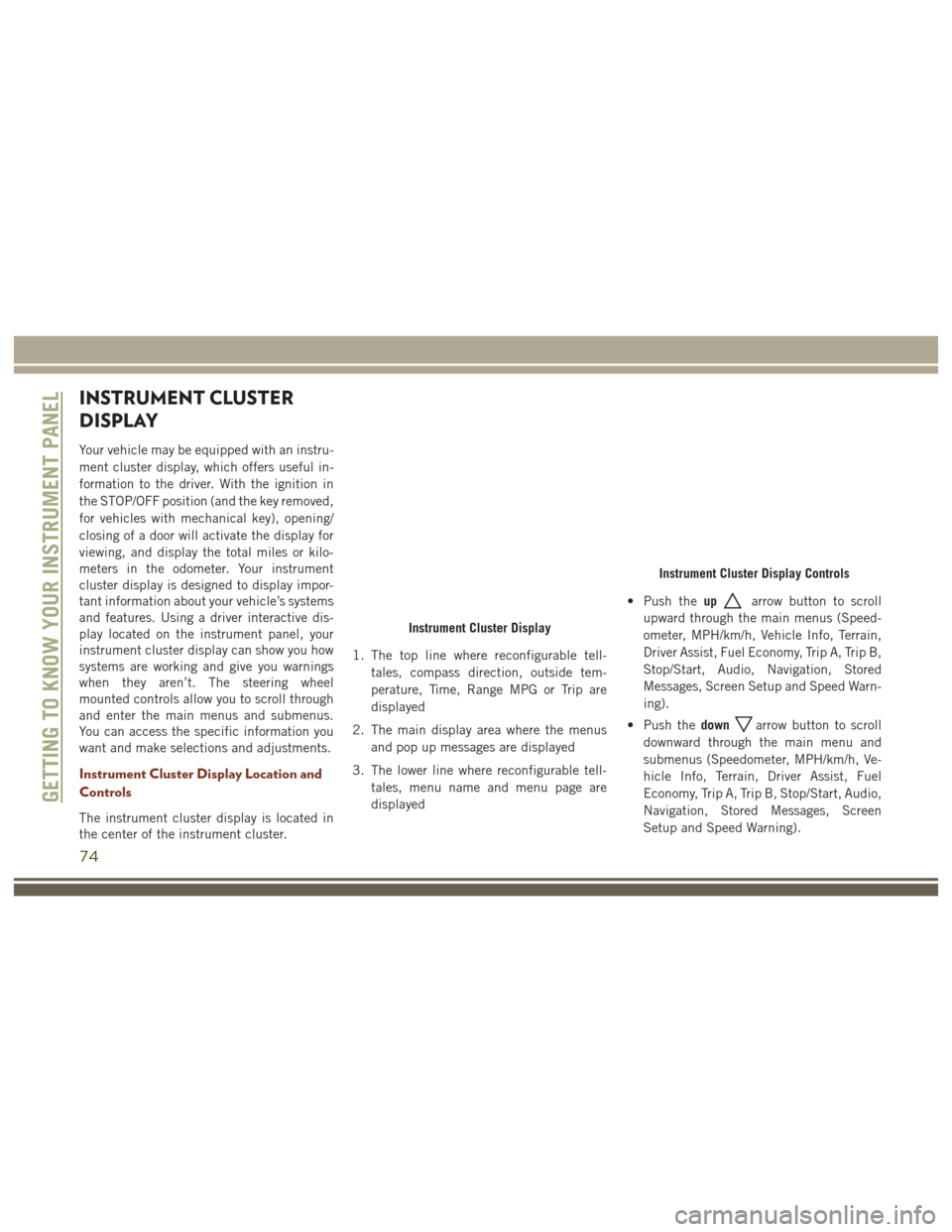
the center of the instrument cluster.1. The top line where reconfigurable tell-
tales, compass direction, outside tem-
perature, Time, Range MPG or Trip are
displayed
2. The main display area where the menus and pop up messages are displayed
3. The lower line where reconfigurable tell- tales, menu name and menu page are
displayed • Push the
up
arrow button to scroll
upward through the main menus (Speed-
ometer, MPH/km/h, Vehicle Info, Terrain,
Driver Assist, Fuel Economy, Trip A, Trip B,
Stop/Start, Audio, Navigation, Stored
Messages, Screen Setup and Speed Warn-
ing).
• Push the down
arrow button to scroll
downward through the main menu and
submenus (Speedometer, MPH/km/h, Ve-
hicle Info, Terrain, Driver Assist, Fuel
Economy, Trip A, Trip B, Stop/Start, Audio,
Navigation, Stored Messages, Screen
Setup and Speed Warning).
Instrument Cluster Display
Instrument Cluster Display Controls
GETTING TO KNOW YOUR INSTRUMENT PANEL
74
Page 78 of 372
NOTE:
Refer to your Owner's Manual on
www.jeep.com/owners/manuals for further
information.
SRT Performance Features
Instrument Cluster Display Performance
Features
The instrument cluster display can be used to
program the following Performance Features.• To access, press and release either the
up
ordownarrow button until “SRT”
appears in the instrument cluster display,
then press and release the right
arrow
button to cycle through the features. Press
the OKbutton to select a feature.
•0-60MPH
(0-100 km/h) • Current G-Force
• 0-100 MPH (0-161 km/h) • Peak G-Force
• 1/8 Mile Timer • Lap Timer
• 1/4 Mile Timer • Lap History
• 60 ft Timer • Top Speed
• Braking Distance
Uconnect SRT Performance Features
WARNING!
Measurement of vehicle statistics with the
Performance Features is intended for off-
highway or off-road use only and should
not be done on any public roadways. It is
recommended that these features be used
in a controlled environment and within the
WARNING!
limits of the law. The capabilities of the
vehicle as measured by the performance
pages must never be exploited in a reck-
less or dangerous manner, which can jeop-
ardize the user’s safety or the safety of
others. Only a safe, attentive, and skillful
driver can prevent accidents.
• To access the SRT Performance Features, press the “Apps” button on the touch-
screen then press the “Performance
Pages” button on the touchscreen.
• The Performance Page includes the fol- lowing menus:
• Home •
Gauges 2
• Timers •
G – Force
• Gauges 1 •
Engine
Diesel Particulate Filter (DPF) Messages
This engine meets all required diesel engine
emissions standards. To achieve these emis-
sions standards, your vehicle is equipped
with a state-of-the-art engine and exhaust
system. These systems are seamlessly inte-
grated into your vehicle and managed by theSRT Performance Features Controls
GETTING TO KNOW YOUR INSTRUMENT PANEL
76
Page 79 of 372
Powertrain Control Module (PCM). The PCM
manages engine combustion to allow the ex-
haust system’s catalyst to trap and burn Par-
ticulate Matter (PM) pollutants, with no input
or interaction on your part.
WARNING!
A hot exhaust system can start a fire if you
park over materials that can burn. Such
materials might be grass or leaves coming
into contact with your exhaust system. Do
not park or operate your vehicle in areas
where your exhaust system can contact
anything that can burn.
Your vehicle has the ability to alert you to
additional maintenance required on your ve-
hicle or engine. Refer to the following mes-
sages that may be displayed on your Instru-
ment Cluster Display:
• Exhaust Filter Nearing Full Safely Drive at
Highway Speeds to Clear — This message
will be displayed on the instrument cluster
display if the exhaust particulate filter
reaches 80% of its maximum storage ca-
pacity. Under conditions of exclusive short
duration and low speed driving cycles, your diesel engine and exhaust after-
treatment system may never reach the
conditions required to cleanse the filter to
remove the trapped PM. If this occurs, the
“Exhaust Filter XX% Full Safely Drive at
Highway Speeds to Remedy” message will
be displayed in the instrument cluster
display. If this message is displayed, you
will hear one chime to assist in alerting
you of this condition. By simply driving
your vehicle at highway speeds for up to
20 minutes, you can remedy the condition
in the particulate filter system and allow
your diesel engine and exhaust after-
treatment system to cleanse the filter to
remove the trapped PM and restore the
system to normal operating condition.
• Exhaust System Regeneration in Process
Continue Driving — This message indicates
that the Diesel Particulate Filter (DPF) is
self-cleaning. Maintain your current driv-
ing condition until regeneration is com-
pleted. •
Exhaust System — Regeneration Completed
— This message indicates that the Diesel
Particulate Filter (DPF) self-cleaning is
completed. If this message is displayed,
you will hear one chime to assist in alert-
ing you of this condition.
• Exhaust System Service Required - See
Dealer — This messages indicates regen-
eration has been disabled due to a system
malfunction. At this point the engine Pow-
ertrain Control Module (PCM) will register
a fault code, the instrument panel will
display a MIL light.
CAUTION!
See your authorized dealer, as damage to
the exhaust system could occur soon with
continued operation.
• Exhaust Filter Full — Power Reduced See
Dealer — This message indicates the PCM
has derated the engine to limit the likeli-
hood of permanent damage to the after-
treatment system. If this condition is not
corrected and a dealer service is not per-
formed, extensive exhaust after-treatment
77