lock JEEP GRAND CHEROKEE 2020 Owner handbook (in English)
[x] Cancel search | Manufacturer: JEEP, Model Year: 2020, Model line: GRAND CHEROKEE, Model: JEEP GRAND CHEROKEE 2020Pages: 378, PDF Size: 6.88 MB
Page 38 of 378
• If the exterior mirrors were manually
folded, they will not automatically unfold.
NOTE:
The Automatic Fold/Unfold Mirrors feature is
not turned on when delivered from the fac-
tory. The Automatic Fold/Unfold Mirrors fea-
ture can be turned on and off using the
Uconnect System. Refer to “Uconnect Set-
tings” in “Multimedia” in your Owner’s
Manual for further information.
Resetting The Power Folding Outside Mirrors
You may need to reset the power folding
mirrors if the following occurs:
• The mirrors are accidentally blocked while
folding.
• The mirrors are accidentally manually
folded/unfolded.
• The mirrors come out of the unfolded posi-
tion.
• The mirrors shake and vibrate at normal
driving speeds.To reset the power folding mirrors: Fold and
unfold them by pushing the button (this may
require multiple button pushes). This resets
them to their normal position.
Tilt Side Mirrors In Reverse (Available
With Memory Seat Only) — If Equipped
Tilt Side Mirrors In Reverse provides auto-
matic outside mirror positioning which will
aid the driver’s view of the ground rearward of
the front doors. Outside mirrors will move
slightly downward from the present position
when the vehicle is shifted into REVERSE.
Outside mirrors will then return to the original
position when the vehicle is shifted out of
REVERSE position. Each stored memory seat
setting will have an associated Tilt Side Mir-
rors In Reverse position.
NOTE:
The Tilt Side Mirrors In Reverse feature is not
turned on when delivered from the factory.
The Tilt Side Mirrors In Reverse feature can
be turned on and off using the Uconnect
System. Refer to “Uconnect Settings” in
“Multimedia” in the Owner’s Manual for fur-
ther information.
EXTERIOR LIGHTS
Headlight Switch
The headlight switch is located on the right
side of the instrument panel, next to the
steering wheel. The headlight switch controls
the operation of the headlights, parking
lights, instrument panel lights, cargo lights,
and fog lights (if equipped).
GETTING TO KNOW YOUR VEHICLE
36
Page 39 of 378
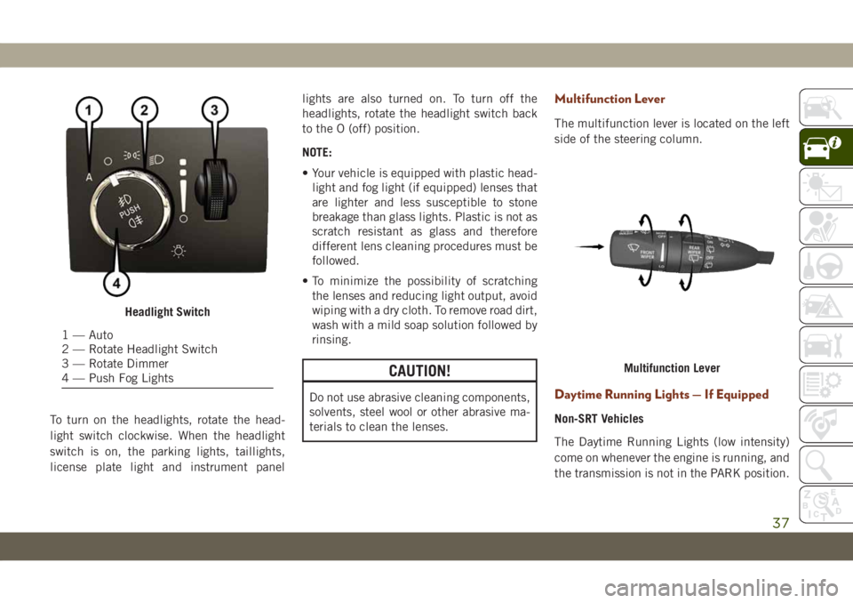
To turn on the headlights, rotate the head-
light switch clockwise. When the headlight
switch is on, the parking lights, taillights,
license plate light and instrument panellights are also turned on. To turn off the
headlights, rotate the headlight switch back
to the O (off) position.
NOTE:
• Your vehicle is equipped with plastic head-
light and fog light (if equipped) lenses that
are lighter and less susceptible to stone
breakage than glass lights. Plastic is not as
scratch resistant as glass and therefore
different lens cleaning procedures must be
followed.
• To minimize the possibility of scratching
the lenses and reducing light output, avoid
wiping with a dry cloth. To remove road dirt,
wash with a mild soap solution followed by
rinsing.
CAUTION!
Do not use abrasive cleaning components,
solvents, steel wool or other abrasive ma-
terials to clean the lenses.
Multifunction Lever
The multifunction lever is located on the left
side of the steering column.
Daytime Running Lights — If Equipped
Non-SRT Vehicles
The Daytime Running Lights (low intensity)
come on whenever the engine is running, and
the transmission is not in the PARK position.
Headlight Switch
1 — Auto
2 — Rotate Headlight Switch
3 — Rotate Dimmer
4 — Push Fog Lights
Multifunction Lever
37
Page 41 of 378
When the system is on, the Headlight Delay
feature is also on. This means the headlights
will stay on for up to 90 seconds after you
turn the ignition switch to the OFF position.
To turn the automatic headlights off, turn the
headlight switch out of the A (auto) position.
NOTE:
The engine must be running before the head-
lights will turn on in the Automatic Mode.
Parking Lights And Panel Lights
To turn on the parking lights and instrument
panel lights, rotate the headlight switch
clockwise. To turn off the parking lights,
rotate the headlight switch back to the O (off)
position.
Headlights On Automatically With
Wipers
If your vehicle is equipped with Automatic
Headlights, it also has this customer-
programmable feature. When your headlights
are in the automatic mode and the engine is
running, they will automatically turn on when
the wiper system is on. This feature is pro-grammable through the Uconnect system
screen. Refer to “Uconnect Settings” in
“Multimedia” in the Owner’s Manual for fur-
ther information.
If your vehicle is equipped with a “Rain
Sensitive Wiper System” and it is activated,
the headlights will automatically turn on after
the wipers complete five wipe cycles within
approximately one minute, and they will turn
off approximately four minutes after the wip-
ers completely stop.
Refer to “Windshield Wipers And Washers” in
“Getting To Know Your Vehicle” for further
information.
NOTE:
When your headlights come on during the
daytime, the instrument panel lights will au-
tomatically dim to the lower nighttime inten-
sity.Adaptive Bi-Xenon High Intensity
Discharge Headlights — If Equipped
This system automatically swivels the head-
light beam pattern horizontally to provide
increased illumination in the direction the
vehicle is steering.NOTE:
• Each time the Adaptive Headlight System
is turned on, the headlights will initialize by
performing a brief sequence of rotations.
• The Adaptive Headlight System is active
only when the vehicle is moving forward.
The Adaptive Headlight System can be
turned on or off using the Uconnect System,
refer to “Uconnect Settings” in “Multime-
dia” in the Owner’s Manual for further infor-
mation.
Headlight Delay
To aid in your exit, your vehicle is equipped
with a headlight delay that will leave the
headlights on for approximately up to 90 sec-
onds. This delay is initiated when the ignition
is turned OFF while the headlight switch is
on, and then the headlight switch is cycled
off. Headlight delay can be cancelled by
either turning the headlight switch on then
off, or by turning the ignition ON.
39
Page 50 of 378
Icon Description
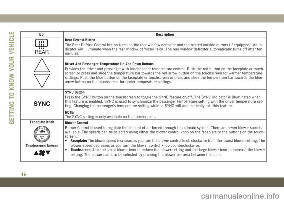
REAR
Rear Defrost Button
The Rear Defrost Control button turns on the rear window defroster and the heated outside mirrors (if equipped). An in-
dicator will illuminate when the rear window defroster is on. The rear window defroster automatically turns off after ten
minutes.
Driver And Passenger Temperature Up And Down Buttons
Provides the driver and passenger with independent temperature control. Push the red button on the faceplate or touch-
screen or press and slide the temperature bar towards the red arrow button on the touchscreen for warmer temperature
settings. Push the blue button on the faceplate or touchscreen or press and slide the temperature bar towards the blue
arrow button on the touchscreen for cooler temperature settings.
SYNC Button
Press the SYNC button on the touchscreen to toggle the SYNC feature on/off. The SYNC indicator is illuminated when
this feature is enabled. SYNC is used to synchronize the passenger temperature setting with the driver temperature set-
ting. Changing the passenger’s temperature setting while in SYNC will automatically exit this feature.
NOTE:
The SYNC setting is only available on the touchscreen.
Faceplate Knob
Touchscreen Buttons
Blower Control
Blower Control is used to regulate the amount of air forced through the climate system. There are seven blower speeds
available. The speeds can be selected using either the blower control knob on the faceplate or the buttons on the touch-
screen.
•Faceplate:The blower speed increases as you turn the blower control knob clockwise from the lowest blower setting. The
blower speed decreases as you turn the blower control knob counterclockwise.
•Touchscreen:Use the small blower icon to reduce the blower setting and the large blower icon to increase the blower
setting. The blower can also be selected by pressing the blower bar area between the icons.GETTING TO KNOW YOUR VEHICLE
48
Page 55 of 378
Push the window switch down for half a
second and release. The window will go down
automatically.
To stop the window from going all the way
down during the Auto-Down operation, pull
up or push down on the switch briefly.
To open the window part way (manually),
push the window switch down briefly and
release.
Auto-Up Feature With Anti-Pinch
Protection
NOTE:
• If the window runs into any obstacle during
auto-closure, it will reverse direction and
then go back down. Remove the obstacle
and use the window switch again to close
the window.
• Any impact due to rough road conditions
may trigger the auto-reverse function unex-
pectedly during auto-closure. If this hap-
pens, pull the switch lightly and hold to
close the window manually.
WARNING!
There is no anti-pinch protection when the
window is almost closed. To avoid personal
injury be sure to clear your arms, hands,
fingers and all objects from the window
path before closing.
Window Lockout Switch
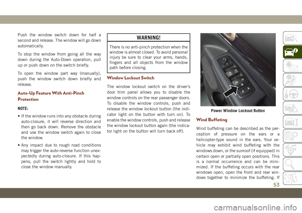
The window lockout switch on the driver's
door trim panel allows you to disable the
window controls on the rear passenger doors.
To disable the window controls, push and
release the window lockout button (the indi-
cator light on the button with turn on). To
enable the window controls, push and release
the window lockout button again (the indica-
tor light on the button will turn back off).
Wind Buffeting
Wind buffeting can be described as the per-
ception of pressure on the ears or a
helicopter-type sound in the ears. Your ve-
hicle may exhibit wind buffeting with the
windows down, or the sunroof (if equipped) in
certain open or partially open positions. This
is a normal occurrence and can be mini-
mized. If the buffeting occurs with the rear
windows open, open the front and rear win-
dows together to minimize the buffeting. If
Power Window Lockout Button
53
Page 56 of 378
the buffeting occurs with the sunroof open,
adjust the sunroof opening to minimize the
buffeting or open any window.
POWER SUNROOF — IF
EQUIPPED
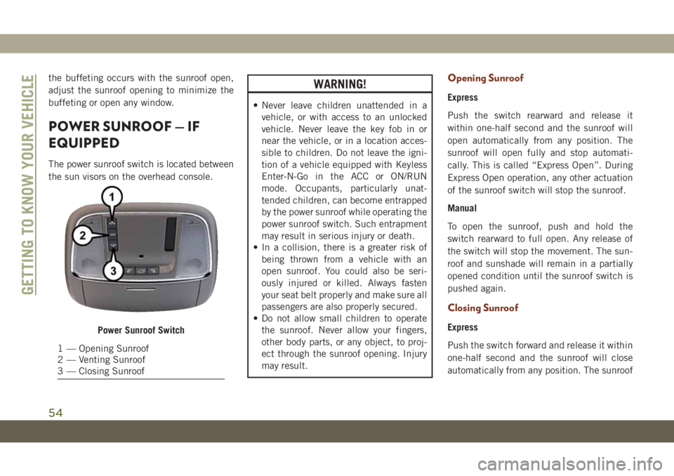
The power sunroof switch is located between
the sun visors on the overhead console.
WARNING!
• Never leave children unattended in a
vehicle, or with access to an unlocked
vehicle. Never leave the key fob in or
near the vehicle, or in a location acces-
sible to children. Do not leave the igni-
tion of a vehicle equipped with Keyless
Enter-N-Go in the ACC or ON/RUN
mode. Occupants, particularly unat-
tended children, can become entrapped
by the power sunroof while operating the
power sunroof switch. Such entrapment
may result in serious injury or death.
• In a collision, there is a greater risk of
being thrown from a vehicle with an
open sunroof. You could also be seri-
ously injured or killed. Always fasten
your seat belt properly and make sure all
passengers are also properly secured.
• Do not allow small children to operate
the sunroof. Never allow your fingers,
other body parts, or any object, to proj-
ect through the sunroof opening. Injury
may result.
Opening Sunroof
Express
Push the switch rearward and release it
within one-half second and the sunroof will
open automatically from any position. The
sunroof will open fully and stop automati-
cally. This is called “Express Open”. During
Express Open operation, any other actuation
of the sunroof switch will stop the sunroof.
Manual
To open the sunroof, push and hold the
switch rearward to full open. Any release of
the switch will stop the movement. The sun-
roof and sunshade will remain in a partially
opened condition until the sunroof switch is
pushed again.
Closing Sunroof
Express
Push the switch forward and release it within
one-half second and the sunroof will close
automatically from any position. The sunroofPower Sunroof Switch
1 — Opening Sunroof
2 — Venting Sunroof
3 — Closing Sunroof
GETTING TO KNOW YOUR VEHICLE
54
Page 58 of 378
5. Once the sunroof has stopped in the Fully
Closed position, release the sunroof
switch. The sunroof is now reset and ready
to use.
COMMANDVIEW SUNROOF
WITH POWER SHADE — IF
EQUIPPED
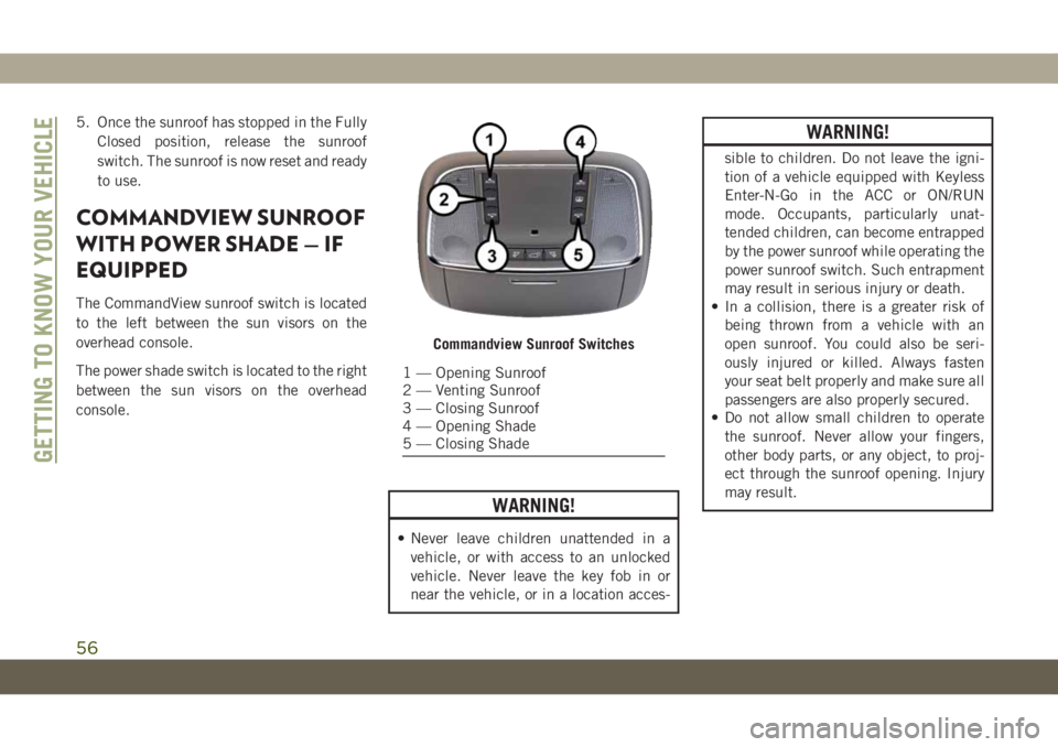
The CommandView sunroof switch is located
to the left between the sun visors on the
overhead console.
The power shade switch is located to the right
between the sun visors on the overhead
console.
WARNING!
• Never leave children unattended in a
vehicle, or with access to an unlocked
vehicle. Never leave the key fob in or
near the vehicle, or in a location acces-
WARNING!
sible to children. Do not leave the igni-
tion of a vehicle equipped with Keyless
Enter-N-Go in the ACC or ON/RUN
mode. Occupants, particularly unat-
tended children, can become entrapped
by the power sunroof while operating the
power sunroof switch. Such entrapment
may result in serious injury or death.
• In a collision, there is a greater risk of
being thrown from a vehicle with an
open sunroof. You could also be seri-
ously injured or killed. Always fasten
your seat belt properly and make sure all
passengers are also properly secured.
• Do not allow small children to operate
the sunroof. Never allow your fingers,
other body parts, or any object, to proj-
ect through the sunroof opening. Injury
may result.
Commandview Sunroof Switches
1 — Opening Sunroof
2 — Venting Sunroof
3 — Closing Sunroof
4 — Opening Shade
5 — Closing Shade
GETTING TO KNOW YOUR VEHICLE
56
Page 61 of 378
HOOD
To Open The Hood
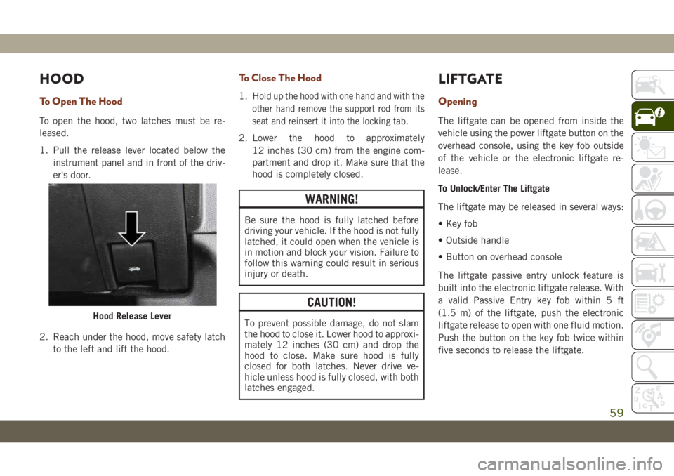
To open the hood, two latches must be re-
leased.
1. Pull the release lever located below the
instrument panel and in front of the driv-
er's door.
2. Reach under the hood, move safety latch
to the left and lift the hood.
To Close The Hood
1. Hold up the hood with one hand and with the
other hand remove the support rod from its
seat and reinsert it into the locking tab.
2. Lower the hood to approximately
12 inches (30 cm) from the engine com-
partment and drop it. Make sure that the
hood is completely closed.
WARNING!
Be sure the hood is fully latched before
driving your vehicle. If the hood is not fully
latched, it could open when the vehicle is
in motion and block your vision. Failure to
follow this warning could result in serious
injury or death.
CAUTION!
To prevent possible damage, do not slam
the hood to close it. Lower hood to approxi-
mately 12 inches (30 cm) and drop the
hood to close. Make sure hood is fully
closed for both latches. Never drive ve-
hicle unless hood is fully closed, with both
latches engaged.
LIFTGATE
Opening
The liftgate can be opened from inside the
vehicle using the power liftgate button on the
overhead console, using the key fob outside
of the vehicle or the electronic liftgate re-
lease.
To Unlock/Enter The Liftgate
The liftgate may be released in several ways:
• Key fob
• Outside handle
• Button on overhead console
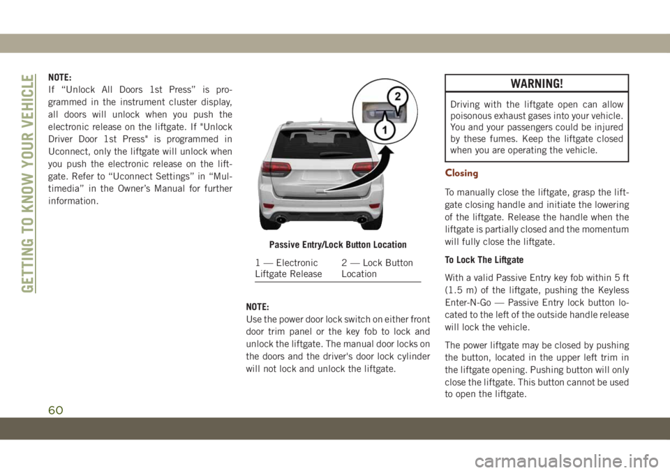
The liftgate passive entry unlock feature is
built into the electronic liftgate release. With
a valid Passive Entry key fob within 5 ft
(1.5 m) of the liftgate, push the electronic
liftgate release to open with one fluid motion.
Push the button on the key fob twice within
five seconds to release the liftgate.
Hood Release Lever
59
Page 62 of 378
NOTE:
If “Unlock All Doors 1st Press” is pro-
grammed in the instrument cluster display,
all doors will unlock when you push the
electronic release on the liftgate. If "Unlock
Driver Door 1st Press" is programmed in
Uconnect, only the liftgate will unlock when
you push the electronic release on the lift-
gate. Refer to “Uconnect Settings” in “Mul-
timedia” in the Owner’s Manual for further
information.
NOTE:
Use the power door lock switch on either front
door trim panel or the key fob to lock and
unlock the liftgate. The manual door locks on
the doors and the driver's door lock cylinder
will not lock and unlock the liftgate.WARNING!
Driving with the liftgate open can allow
poisonous exhaust gases into your vehicle.
You and your passengers could be injured
by these fumes. Keep the liftgate closed
when you are operating the vehicle.
Closing
To manually close the liftgate, grasp the lift-
gate closing handle and initiate the lowering
of the liftgate. Release the handle when the
liftgate is partially closed and the momentum
will fully close the liftgate.
To Lock The Liftgate
With a valid Passive Entry key fob within 5 ft
(1.5 m) of the liftgate, pushing the Keyless
Enter-N-Go — Passive Entry lock button lo-
cated to the left of the outside handle release
will lock the vehicle.
The power liftgate may be closed by pushing
the button, located in the upper left trim in
the liftgate opening. Pushing button will only
close the liftgate. This button cannot be used
to open the liftgate.
Passive Entry/Lock Button Location
1 — Electronic
Liftgate Release2 — Lock Button
Location
GETTING TO KNOW YOUR VEHICLE
60
Page 63 of 378
NOTE:
The liftgate unlock feature is built into the
electronic liftgate release.
Power Liftgate — If Equipped
The power liftgate may be
opened by pushing the electronic
liftgate release (refer to “Keyless
Enter-N-Go — Passive Entry” located in
“Getting To Know Your Vehicle” in your Own-
er’s Manual for further information), or bypushing the liftgate button on the key fob.
Push the liftgate button on the key fob twice
within five seconds to open the power lift-
gate. Once the liftgate is open, pushing the
button twice within five seconds a second
time will close the liftgate.
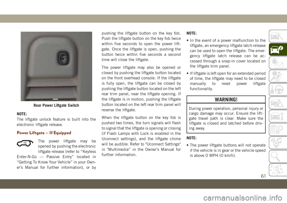
The power liftgate may also be opened or
closed by pushing the liftgate button located
on the front overhead console. If the liftgate
is fully open, the liftgate can be closed by
pushing the liftgate button located on the left
rear trim panel, near the liftgate opening. If
the liftgate is in motion, pushing the liftgate
button located on the left rear trim panel will
reverse the liftgate.
When the liftgate button on the key fob is
pushed two times, the turn signals will flash
to signal that the liftgate is opening or closing
(if Flash Lamps with Lock is enabled in the
Uconnect settings), and the liftgate chime
will be audible. Refer to "Uconnect Settings"
in "Multimedia” in the Owner’s Manual for
further information.NOTE:
• In the event of a power malfunction to the
liftgate, an emergency liftgate latch release
can be used to open the liftgate. The emer-
gency liftgate latch release can be ac-
cessed through a snap-in cover located on
the liftgate trim panel.
• If liftgate is left open for an extended period
of time, the liftgate may need to be closed
manually to reset power liftgate
functionality.
WARNING!
During power operation, personal injury or
cargo damage may occur. Ensure the lift-
gate travel path is clear. Make sure the
liftgate is closed and latched before driv-
ing away.
NOTE:
• The power liftgate buttons will not operate
if the vehicle is in gear or the vehicle speed
is above 0 MPH (0 km/h).Rear Power Liftgate Switch
2
61