tow JEEP GRAND CHEROKEE 2020 Owner handbook (in English)
[x] Cancel search | Manufacturer: JEEP, Model Year: 2020, Model line: GRAND CHEROKEE, Model: JEEP GRAND CHEROKEE 2020Pages: 378, PDF Size: 6.88 MB
Page 141 of 378
WARNING!
• The top tether anchorages are not visible
until the gap panel is folded down. Do
not use the visible cargo tie down hooks,
located on the floor behind the seats, to
attach a child restraint tether anchor.
• An incorrectly anchored tether strap
could lead to increased head motion and
possible injury to the child. Use only the
anchorage position directly behind the
child seat to secure a child restraint top
tether strap.
• If your vehicle is equipped with a split
rear seat, make sure the tether strap
does not slip into the opening between
the seatbacks as you remove slack in the
strap.
How To Stow An Unused Switchable-ALR
(ALR) Seat Belt:
When using the ISOFIX attaching system to
install a child restraint, stow all ALR seat
belts that are not being used by other occu-
pants or being used to secure child restraints.
An unused belt could injure a child if they
play with it and accidentally lock the seat beltretractor. Before installing a child restraint
using the ISOFIX system, buckle the seat belt
behind the child restraint and out of the
child’s reach. If the buckled seat belt inter-
feres with the child restraint installation, in-
stead of buckling it behind the child re-
straint, route the seat belt through the child
restraint belt path and then buckle it. Do not
lock the seat belt. Remind all children in the
vehicle that the seat belts are not toys and
that they should not play with them.
Installing Child Restraints Using The Ve-
hicle Seat Belt
Child restraint systems are designed to be
secured in vehicle seats by lap belts or the lap
belt portion of a lap/shoulder belt.
WARNING!
• Improper installation or failure to prop-
erly secure a child restraint can lead to
failure of the restraint. The child could
be badly injured or killed.
• Follow the child restraint manufacturer’s
directions exactly when installing an in-
fant or child restraint.The seat belts in the rear passenger seating
positions are equipped with a Switchable
Automatic Locking Retractor (ALR) that is
designed to keep the lap portion of the seat
belt tight around the child restraint. The ALR
retractor can be “switched” into a locked
mode by pulling all of the webbing out of the
retractor and then letting the webbing retract
back into the retractor. If it is locked, the ALR
will make a clicking noise while the webbing
is pulled back into the retractor. Refer to the
“Automatic Locking Mode” description in
“Switchable Automatic Locking Retractors
(ALR)” under “Occupant Restraint Systems”
for additional information on ALR.
Installing A Child Restraint With A Switch-
able Automatic Locking Retractor (ALR)
Child restraint systems are designed to be
secured in vehicle seats by lap belts or the lap
belt portion of a lap/shoulder belt.
WARNING!
• Improper installation or failure to prop-
erly secure a child restraint can lead to
139
Page 145 of 378
WARNING!
• NEVER place any objects under the floor
mat (e.g., towels, keys, etc.). These ob-
jects could change the position of the
floor mat and may cause interference
with the accelerator, brake, or clutch
pedals.
• If the vehicle carpet has been removed
and re-installed, always properly attach
carpet to the floor and check the floor
mat fasteners are secure to the vehicle
carpet. Fully depress each pedal to
check for interference with the accelera-
tor, brake, or clutch pedals then re-
install the floor mats.
• It is recommended to only use mild soap
and water to clean your floor mats. After
cleaning, always check your floor mat
has been properly installed and is se-
cured to your vehicle using the floor mat
fasteners by lightly pulling mat.
Periodic Safety Checks You Should Make
Outside The Vehicle
Tires
Examine tires for excessive tread wear and
uneven wear patterns. Check for stones,
nails, glass, or other objects lodged in the
tread or sidewall. Inspect the tread for cuts
and cracks. Inspect sidewalls for cuts,
cracks, and bulges. Check the wheel nuts for
tightness. Check the tires (including spare)
for proper cold inflation pressure.
Lights
Have someone observe the operation of brake
lights and exterior lights while you work the
controls. Check turn signal and high beam
indicator lights on the instrument panel.
Door Latches
Check for proper closing, latching, and locking.
Fluid Leaks
Check area under the vehicle after overnight
parking for fuel, coolant, oil, or other fluid
leaks. Also, if gasoline fumes are detected or
if fuel, or brake fluid leaks are suspected. The
cause should be located and corrected
immediately.
WARNING!
To prevent SERIOUS INJURY or DEATH
when using “Track-Use” parts and equip-
ment:
• NEVER use any “Track-Use” equipment
on public roads. FCA does not authorize
the use of “Track-Use” equipment on
public roads.
• The intended use of “Track-Use” parts is
for race vehicles on race tracks. To help
ensure the safety of the race driver, en-
gineers should supervise the installation
of “Track-Use” parts.
• FCA does not authorize the installation
or use of any part noted as “Track-Use”
on any new vehicle prior to its first retail
sale.
143
Page 155 of 378
While cruising, brief full-throttle acceleration
within the limits of local traffic laws contrib-
utes to a good break-in. However, wide-open
throttle acceleration in low gear can be det-
rimental and should be avoided.
The engine oil, transmission fluid, and axle
lubricant installed at the factory is high-
quality and energy-conserving. Oil, fluid, and
lubricant changes should be consistent with
anticipated climate and conditions under
which vehicle operations will occur. For the
recommended viscosity and quality grades,
refer to “Fluids And Lubricants” in "Techni-
cal Specifications”.
CAUTION!
Never use Non-Detergent Oil or Straight
Mineral Oil in the engine or damage may
result.NOTE:
A new engine may consume some oil during
its first few thousand miles (kilometers) of
operation. This should be considered a nor-
mal part of the break-in and not interpreted
as an indication of difficulty. Please check
your oil level with the engine oil indicator
often during the break in period. Add oil as
required.
Diesel Engine
The diesel engine does not require a break-in
period due to its construction. Normal opera-
tion is allowed, providing the following rec-
ommendations are followed:
• Warm up the engine before placing it under
load.
• Do not operate the engine at idle for pro-
longed periods.
• Use the appropriate transmission gear to
prevent engine lugging.
• Observe vehicle oil pressure and tempera-
ture indicators.
• Check the coolant and oil levels frequently.• Vary throttle position at highway speeds
when carrying or towing significant weight.
NOTE:
Light duty operation such as light trailer tow-
ing or no load operation will extend the time
before the engine is at full efficiency. Re-
duced fuel economy and power may be seen
at this time.
The engine oil installed in the engine at the
factory is a high-quality energy conserving
type lubricant. Oil changes should be consis-
tent with anticipated climate conditions un-
der which vehicle operations will occur. The
recommended viscosity and quality grades
are shown under “Fluids And Lubricants” in
"Technical Specifications” in this manual.
NON-DETERGENT OR STRAIGHT MINERAL
OILS MUST NEVER BE USED.
SRT Engines
The following tips will be helpful in obtaining
optimum performance and maximum dura-
bility for your new SRT Vehicle.
Despite modern technology and World Class
manufacturing methods, the moving parts of
the vehicle must still wear in with each other.
153
Page 158 of 378
placing the transmission in PARK. This sys-
tem also locks the transmission in PARK
whenever the ignition is in the OFF mode.
NOTE:
The transmission is NOT locked in PARK
when the ignition is in the ACC mode (even
though the engine will be off). Ensure that
the transmission is in PARK, and the ignition
isOFF(not in ACC mode) before exiting the
vehicle.
Brake/Transmission Shift Interlock
System
This vehicle is equipped with a Brake Trans-
mission Shift Interlock system (BTSI) that
holds the transmission gear selector in PARK
unless the brakes are applied. To shift the
transmission out of PARK, the engine must
be running and the brake pedal must be
pressed. The brake pedal must also be
pressed to shift from NEUTRAL into DRIVE or
REVERSE when the vehicle is stopped or
moving at low speeds.
Fuel Economy (ECO) Mode
The Fuel Economy (ECO) mode can improve
the vehicle's overall fuel economy during nor-
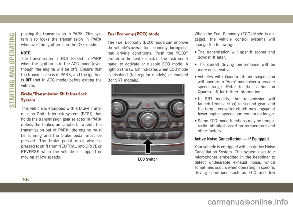
mal driving conditions. Push the “ECO”
switch in the center stack of the instrument
panel to activate or disable ECO mode. A
light on the switch indicates when ECO mode
is disabled (for regular models) or enabled
(for SRT models).When the Fuel Economy (ECO) Mode is en-
gaged, the vehicle control systems will
change the following:
• The transmission will upshift sooner and
downshift later.
• The overall driving performance will be
more conservative.
• Vehicles with Quadra-Lift air suspension
will operate in "Aero" mode over a broader
speed range. Refer to the section on
Quadra-Lift for further information.
• In SRT models, the transmission will
launch (from a stop) in second gear, and
the torque converter clutch may engage at
lower engine speeds and remain on longer.
• Some ECO mode functions may be tempo-
rarily inhibited based on temperature and
other factors.
Active Noise Cancellation — If Equipped
Your vehicle is equipped with an Active Noise
Cancellation System. This system uses four
microphones embedded in the headliner to
detect undesirable exhaust noise, which
sometimes occurs when operating in specific
driving conditions such as ECO and Tow
ECO Switch
STARTING AND OPERATING
156
Page 159 of 378
mode. An onboard frequency generator cre-
ates counteracting sound waves through the
audio system to help keep the vehicle quiet.
Eight–Speed Automatic Transmission
Your vehicle is equipped with a fuel efficient
8 speed transmission. The gear selector is
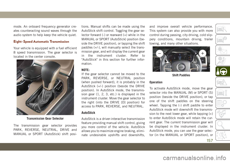
located in the center console.
The transmission gear selector provides
PARK, REVERSE, NEUTRAL, DRIVE and
MANUAL or SPORT (AutoStick) shift posi-tions. Manual shifts can be made using the
AutoStick shift control. Toggling the gear se-
lector forward (-) or rearward (+) while in the
MANUAL or SPORT (AutoStick) position (be-
side the DRIVE position), or tapping the shift
paddles (+/-), will manually select the trans-
mission gear, and will display the current gear
in the instrument cluster. Refer to
"AutoStick" in this section for further infor-
mation.
NOTE:
If the gear selector cannot be moved to the
PARK, REVERSE, or NEUTRAL position
(when pushed forward), it is probably in the
AutoStick (+/-) position (beside the DRIVE
position). In AutoStick mode, the transmis-
sion gear (1, 2, 3, etc.) is displayed in the
instrument cluster. Move the gear selector to
the right (into the DRIVE [D] position) for
access to PARK, REVERSE, and NEUTRAL.
AutoStick
AutoStick is a driver-interactive transmission
feature providing manual shift control, giving
you more control of the vehicle. AutoStick
allows you to maximize engine braking, elimi-
nate undesirable upshifts and downshifts,and improve overall vehicle performance.
This system can also provide you with more
control during passing, city driving, cold slip-
pery conditions, mountain driving, trailer
towing, and many other situations.
Operation
To activate AutoStick mode, move the gear
selector into the MANUAL (M) or SPORT (S)
position (beside the DRIVE position), or tap
one of the shift paddles on the steering
wheel. Tapping the (-) shift paddle to enter
AutoStick mode will downshift the transmis-
sion to the next lower gear, while tapping (+)
to enter AutoStick mode will retain the cur-
rent gear. The current transmission gear will
be displayed in the instrument cluster. In
AutoStick mode, you can use the gear selec-
tor (in the MANUAL or SPORT position), orTransmission Gear Selector
Shift Paddles
157
Page 162 of 378
When operating your vehicle in 4WD LOW,
the engine speed is approximately three
times that of the 4WD HI position at a given
road speed. Take care not to overspeed the
engine and do not exceed 25 mph (40 km/h).
Proper operation of four-wheel drive vehicles
depends on tires of equal size, type, and
circumference on each wheel. Any difference
will adversely affect shifting and cause dam-
age to the transfer case.
Because four-wheel drive provides improved
traction, there is a tendency to exceed safe
turning and stopping speeds. Do not go faster
than road conditions permit.
WARNING!
You or others could be injured or killed if
you leave the vehicle unattended with the
transfer case in the NEUTRAL position
without first fully engaging the parking
brake. The transfer case NEUTRAL posi-
tion disengages both the front and rear
drive shafts from the powertrain and will
allow the vehicle to roll, even if the trans-
mission is in PARK. The parking brake
WARNING!
should always be applied when the driver
is not in the vehicle.
Shift Positions
For additional information on the appropriate
use of each 4WD system mode position, see
the information below:
4WD AUTO
This range is used on surfaces such as ice,
snow, gravel, sand, and dry hard pavement.
NOTE:
Refer to “Selec-Terrain — If Equipped” fur-
ther on in this section for further information
on the various positions and their intended
usages.
NEUTRAL
This range disengages the driveline from the
powertrain. It is to be used for flat towing
behind another vehicle. Refer to “Recre-
ational Towing” in “Starting And Operating”
for further information.
WARNING!
You or others could be injured or killed if
you leave the vehicle unattended with the
transfer case in the NEUTRAL position
without first fully engaging the parking
brake. The transfer case NEUTRAL posi-
tion disengages both the front and rear
drive shafts from the powertrain and will
allow the vehicle to roll, even if the trans-
mission is in PARK. The parking brake
should always be applied when the driver
is not in the vehicle.
4WD LOW
This range is for low speed four-wheel drive.
It provides an additional gear reduction
which allows for increased torque to be deliv-
ered to both the front and rear wheels while
providing maximum pulling power for loose,
slippery road surfaces only. Do not exceed
25 mph (40 km/h).
NOTE:
Refer to “Selec-Terrain — If Equipped” for
further information on the various positions
and their intended usages.
STARTING AND OPERATING
160
Page 164 of 378
4. If vehicle is equipped with Quadra-Lift air
suspension, ensure the vehicle is set to
Normal Ride Height.
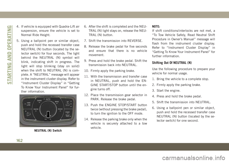
5. Using a ballpoint pen or similar object,
push and hold the recessed transfer case
NEUTRAL (N) button (located by the se-
lector switch) for four seconds. The light
behind the NEUTRAL (N) symbol will
blink, indicating shift in progress. The
light will stop blinking (stay on solid)
when the shift to NEUTRAL (N) is com-
plete. A “NEUTRAL” message will appear
in the instrument cluster display. Refer to
“Instrument Cluster Display” in “Getting
To Know Your Instrument Panel” for fur-
ther information.6. After the shift is completed and the NEU-
TRAL (N) light stays on, release the NEU-
TRAL (N) button.
7. Shift the transmission into REVERSE.
8. Release the brake pedal for five seconds
and ensure that there is no vehicle
movement.
9. Press and hold the brake pedal. Shift the
transmission back into NEUTRAL.
10. Firmly apply the parking brake.
11. With the transmission and transfer case
in NEUTRAL, push and hold the EN-
GINE START/STOP button until the en-
gine turns off.
12. Place the transmission gear selector in
PARK. Release the brake pedal.
13. Push the ENGINE STOP/START button
twice (without pressing the brake pedal),
to turn the ignition to the OFF mode.
14. Release the parking brake only when the
vehicle is securely attached to a tow
vehicle.NOTE:
If shift conditions/interlocks are not met, a
“To Tow Vehicle Safely, Read Neutral Shift
Procedure in Owner’s Manual” message will
flash from the instrument cluster display.
Refer to “Instrument Cluster Display” in
“Getting To Know Your Instrument Panel” for
further information.
Shifting Out Of NEUTRAL (N)
Use the following procedure to prepare your
vehicle for normal usage.
1. Bring the vehicle to a complete stop.
2. Firmly apply the parking brake.
3. Start the engine.
4. Press and hold the brake pedal.
5. Shift the transmission into NEUTRAL.
6. Using a ballpoint pen or similar object,
push and hold the recessed transfer case
NEUTRAL (N) button (located by the se-
lector switch) for one second.
NEUTRAL (N) Switch
STARTING AND OPERATING
162
Page 168 of 378
Transport Mode
To assist with flat bed towing, the air suspen-
sion system has a feature which will put the
vehicle into Entry/Exit height and disable the
automatic load leveling system. Refer to
“Uconnect Settings” in “Multimedia” for fur-
ther information.
NOTE:
This mode is intended to be enabled with
engine running.
Suspension Display Messages Mode
The “Suspension Display Messages” setting
allows you to only display suspension warn-
ings. Refer to “Uconnect Settings” in “Mul-
timedia” for further information.
NOTE:
This mode is intended to be enabled with
engine running.
Wheel Alignment Mode
Before performing a wheel alignment this
mode must be enabled. Refer to “Uconnect
Settings” in “Multimedia” for further infor-
mation.NOTE:
This mode is intended to be enabled with
engine running.
If equipped with a touch screen radio all
enabling/disabling of air suspension features
must be done through the radio. Refer to
“Uconnect Settings” in “Multimedia” for fur-
ther information.
Instrument Cluster Display Messages
When the appropriate conditions exist, a
message will appear in the instrument clus-
ter. Refer to “Instrument Cluster Display” in
“Getting To Know Your Instrument Panel” for
further information.
Operation
The indicator lamps 3 through 6 will illumi-
nate to show the current position of the
vehicle. Flashing indicator lamps will show a
position which the system is working to
achieve. When raising, if multiple indicator
lamps are flashing on the “UP” button, the
highest flashing indicator lamp is the posi-
tion the system is working to achieve. Whenlowering, if multiple indicators are flashing
on the "DOWN" button the lowest solid indi-
cator lamp is the position the system is work-
ing to achieve.
Pushing the “UP” button once will move the
suspension one position higher from the cur-
rent position, assuming all conditions are
met (i.e. engine running, speed below thresh-
old, etc). The “UP” button can be pushed
multiple times, each push will raise the re-
quested level by one position up to a maxi-
mum position of OR2 or the highest position
allowed based on current conditions (i.e. ve-
hicle speed, etc).
Pushing the “DOWN” button once will move
the suspension one position lower from the
current level, assuming all conditions are met
(i.e. engine running, doors closed, speed be-
low threshold, etc). The “DOWN” button can
be pressed multiple times. Each push will
lower the requested level by one position
down to a minimum of Park Mode or the
lowest position allowed based on current con-
ditions (i.e. vehicle speed, etc.)
STARTING AND OPERATING
166
Page 171 of 378
Refer to “SRT Drive Modes” in the “Multime-
dia” section in your Owner’s Manual for fur-
ther information.
Selec-Track consists of the following posi-
tions:
•Sport– Dry weather, on-road calibration.
Performance based tuning that provides a
rear wheel drive feel but with improved
handling and acceleration over a two-wheel
drive vehicle. This feature will reset to
AUTO on an ignition cycle.
•Snow– Tuning set for additional stability in
inclement weather. Use on and off road on
loose traction surfaces such as snow. This
feature will reset to AUTO upon an ignition
cycle.
•Auto– Fully automatic full time four-wheel
drive operation can be used on and off road.
Balances traction with seamless steering
feel to provide improved handling and ac-
celeration over two-wheel drive vehicles.•Track– Track road calibration for use on
high traction surfaces. Driveline is maxi-
mized for traction. Some binding may be
felt on less forgiving surfaces. This feature
will reset to AUTO on an ignition cycle.
•To w– Use this mode for towing and hauling
heavy loads. Vehicle suspension will go to
sport mode. Trailer sway control is enabled
in the ESC system. This feature will reset to
AUTO upon an ignition cycle.
Custom
This mode allows the driver to create a cus-
tom vehicle configuration that is saved for
quick selection of favorite settings. The sys-
tem will return to AUTO mode when the
ignition switch is cycled from RUN to OFF to
RUN, if this mode is selected. While in Cus-
tom Mode the Stability, Transmission, Steer-
ing, Suspension, all-wheel drive set up, and
Paddle shifter settings may be configured
through the custom mode set-up.
NOTE:
Refer to “SRT Drive Modes” in the “Multime-
dia” section in your Owner’s Manual for fur-
ther information.
Active Damping System
This vehicle is equipped with an electronic
controlled damping system. This system re-
duces body roll and pitch in many driving
situations including cornering, acceleration
and braking. There are 3 modes:
•Street Mode(Available in terrain positions
AUTO, SNOW and CUSTOM.) — Used dur-
ing highway speeds where a touring sus-
pension feel is desired.
•Sport Mode(Available in terrain positions
AUTO, SPORT, CUSTOM and TOW.) — Pro-
vides a firm suspension for better handling.
•Track Mode(Available in terrain positions
AUTO, TRACK and CUSTOM.) — Provides
a full firm suspension for an aggressive
track experience.
Refer to “SRT Drive Modes” in the “Multime-
dia” section in your Owner’s Manual for fur-
ther information.
169
Page 181 of 378
WARNING!
• Drivers must be careful when backing up
even when using ParkSense. Always
check carefully behind your vehicle, look
behind you, and be sure to check for
pedestrians, animals, other vehicles, ob-
structions, and blind spots before back-
ing up. You are responsible for safety
and must continue to pay attention to
your surroundings. Failure to do so can
result in serious injury or death.
• Before using ParkSense, it is strongly
recommended that the ball mount and
hitch ball assembly is disconnected
from the vehicle when the vehicle is not
used for towing. Failure to do so can
result in injury or damage to vehicles or
obstacles because the hitch ball will be
much closer to the obstacle than the rear
fascia when the loudspeaker sounds the
continuous tone. Also, the sensors could
detect the ball mount and hitch ball
assembly, depending on its size and
shape, giving a false indication that an
obstacle is behind the vehicle.
CAUTION!
• ParkSense is only a parking aid and it is
unable to recognize every obstacle, in-
cluding small obstacles. Parking curbs
might be temporarily detected or not
detected at all. Obstacles located above
or below the sensors will not be detected
when they are in close proximity.
• The vehicle must be driven slowly when
using ParkSense in order to be able to
stop in time when an obstacle is de-
tected. It is recommended that the
driver looks over his/her shoulder when
using ParkSense.
PARKSENSE FRONT AND
REAR PARK ASSIST — IF
EQUIPPED
The ParkSense Park Assist system provides
visual and audible indications of the distance
between the rear and/or front fascia and a
detected obstacle when backing up or moving
forward, e.g. during a parking maneuver. If
your vehicle is equipped with an automatictransmission, the vehicle brakes may be au-
tomatically applied and released when per-
forming a reverse parking maneuver if the
system detects a possible collision with an
obstacle.
Refer to “ParkSense System Usage Precau-
tions” in “Starting And Operating” in your
Owner’s Manual for limitations of this system
and recommendations.
ParkSense will retain the last system state
(enabled or disabled) from the last ignition
cycle when the ignition is changed to the
ON/RUN position.
ParkSense Sensors
The four ParkSense sensors (or six, if
equipped with Active Park Assist), located in
the rear fascia/bumper, monitor the area be-
hind the vehicle that is within the sensors’
field of view. The sensors can detect ob-
stacles from approximately 12 inches
(30 cm) up to 79 inches (200 cm) from the
rear fascia/bumper in the horizontal direc-
tion, depending on the location, type and
orientation of the obstacle.
179