JEEP LIBERTY 2002 KJ / 1.G Workshop Manual
Manufacturer: JEEP, Model Year: 2002, Model line: LIBERTY, Model: JEEP LIBERTY 2002 KJ / 1.GPages: 1803, PDF Size: 62.3 MB
Page 171 of 1803
TORQUE
TORQUE SPECIFICATIONS
DESCRIPTION N´m Ft. Lbs. In. Lbs.
Brake Pedal Pivot Bolt/Nut 35 26 Ð
Brake Booster Mounting Nuts 39 29 Ð
Brake Pedal to the Column
Nut22.6 Ð 200
Master Cylinder Mounting
Nuts25 Ð 220
Master Cylinder Brake Lines 20 15 180
Combination Valve Mounting
Nuts17.5 Ð 155
Combination Valve Brake
Lines20 15 180
Caliper Mounting Bolts 15 11 Ð
Caliper Brake Hose Bolt 31 23 Ð
Wheel Cylinder Mounting
Bolts10 7 Ð
Wheel Cylinder Brake Line 14 Ð 124
Parking Brake Lever Screws 10-14 7-10 Ð
Parking Brake Lever Bracket
Screws10-14 7-10 Ð
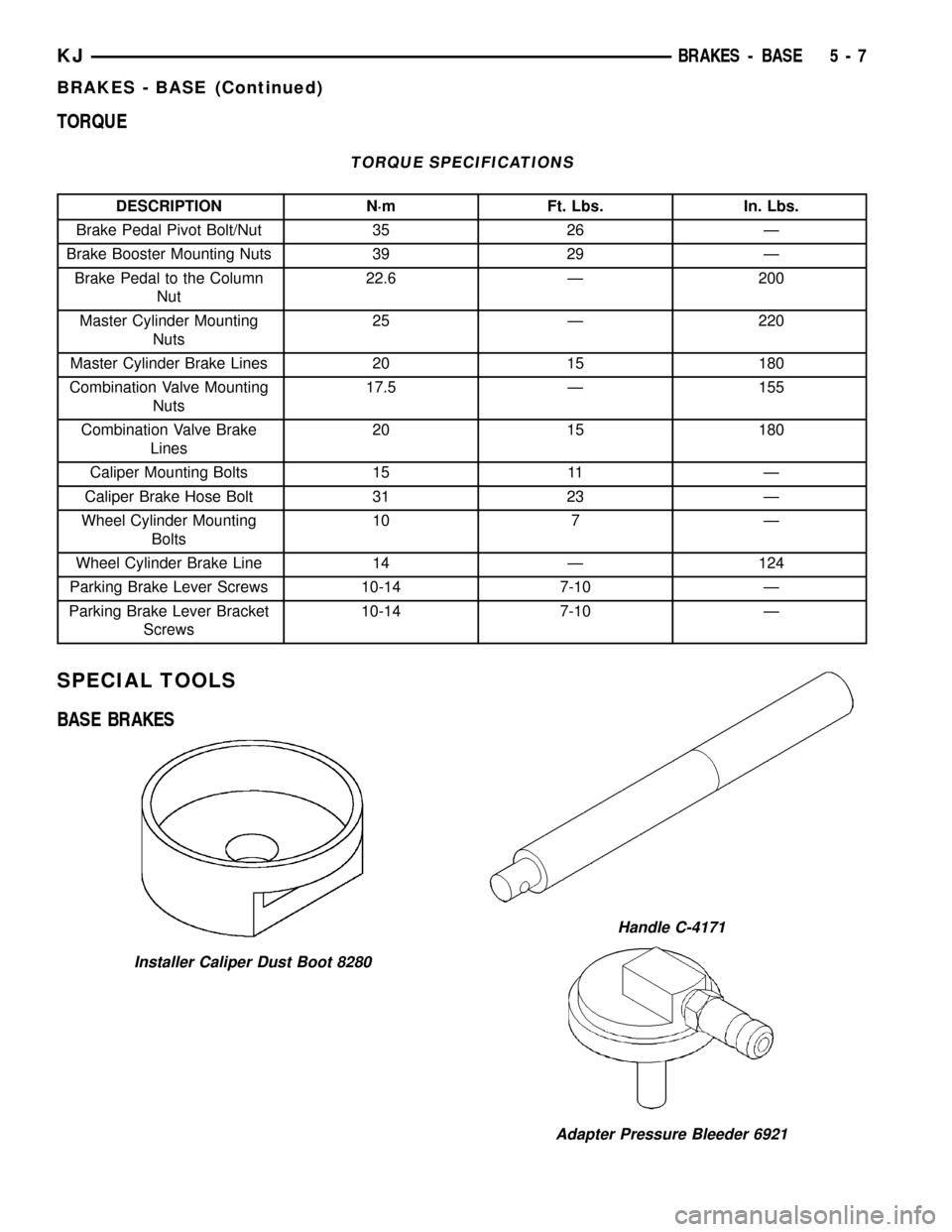
SPECIAL TOOLS
BASE BRAKES
Installer Caliper Dust Boot 8280
Handle C-4171
Adapter Pressure Bleeder 6921
KJBRAKES - BASE 5 - 7
BRAKES - BASE (Continued)
Page 172 of 1803

BRAKE LINES
DESCRIPTION
Flexible rubber hose is used at both front brakes
and at the rear axle junction block. Double walled
steel tubing is used to connect the master cylinder to
the major hydraulic braking components and then to
the flexible rubber hoses. Double inverted style and
ISO style flares are used on the brake lines.
DIAGNOSIS AND TESTING - BRAKE LINE AND
HOSES
Flexible rubber hose is used at both front brakes
and at the rear axle junction block. Inspect the hoses
whenever the brake system is serviced, at every
engine oil change, or whenever the vehicle is in for
service.
Inspect the hoses for surface cracking, scuffing, or
worn spots. Replace any brake hose immediately if
the fabric casing of the hose is exposed due to cracks
or abrasions.
Also check brake hose installation. Faulty installa-
tion can result in kinked, twisted hoses, or contact
with the wheels and tires or other chassis compo-
nents. All of these conditions can lead to scuffing,
cracking and eventual failure.
The steel brake lines should be inspected periodi-
cally for evidence of corrosion, twists, kinks, leaks, or
other damage. Heavily corroded lines will eventually
rust through causing leaks. In any case, corroded or
damaged brake lines should be replaced.
Factory replacement brake lines and hoses are rec-
ommended to ensure quality, correct length and supe-
rior fatigue life. Care should be taken to make sure
that brake line and hose mating surfaces are clean
and free from nicks and burrs. Also remember that
right and left brake hoses are not interchangeable.
Use new copper seal washers at all caliper connec-
tions. Be sure brake line connections are properly
made (not cross threaded) and tightened to recom-
mended torque.
STANDARD PROCEDURE
STANDARD PROCEDURE - DOUBLE INVERTED
FLARING
A preformed metal brake tube is recommended and
preferred for all repairs. However, double-wall steel
tube can be used for emergency repair when factory
replacement parts are not readily available.
Special bending tools are needed to avoid kinking
or twisting of metal brake tubes. Special flaring tools
are needed to make a double inverted flare or ISO
flare.(1) Cut off damaged tube with Tubing Cutter.
(2) Ream cut edges of tubing to ensure proper
flare.
(3) Install replacement tube nut on the tube.
(4) Insert tube in flaring tool.
(5) Place gauge form over the end of the tube.
(6) Push tubing through flaring tool jaws until
tube contacts recessed notch in gauge that matches
tube diameter.
(7) Tighten the tool bar on the tube
(8) Insert plug on gauge in the tube. Then swing
compression disc over gauge and center tapered flar-
ing screw in recess of compression disc (Fig. 2).
(9) Tighten tool handle until plug gauge is
squarely seated on jaws of flaring tool. This will start
the inverted flare.
(10) Remove the plug gauge and complete the
inverted flare.
STANDARD PROCEDURE - ISO FLARING
A preformed metal brake tube is recommended and
preferred for all repairs. However, double-wall steel
tube can be used for emergency repair when factory
replacement parts are not readily available.
Special bending tools are needed to avoid kinking
or twisting of metal brake tubes. Special flaring tools
are needed to make a double inverted flare or ISO
flare.
To make a ISO flare use a ISO brake flaring tool or
equivalent.
(1) Cut off damaged tube with Tubing Cutter.
(2) Remove any burrs from the inside of the tube.
(3) Install tube nut on the tube.
Fig. 2 Inverted
5 - 8 BRAKES - BASEKJ
Page 173 of 1803
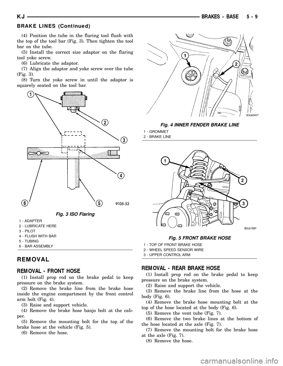
(4) Position the tube in the flaring tool flush with
the top of the tool bar (Fig. 3). Then tighten the tool
bar on the tube.
(5) Install the correct size adaptor on the flaring
tool yoke screw.
(6) Lubricate the adaptor.
(7) Align the adaptor and yoke screw over the tube
(Fig. 3).
(8) Turn the yoke screw in until the adaptor is
squarely seated on the tool bar.
REMOVAL
REMOVAL - FRONT HOSE
(1) Install prop rod on the brake pedal to keep
pressure on the brake system.
(2) Remove the brake line from the brake hose
inside the engine compartment by the front control
arm bolt (Fig. 4).
(3) Raise and support vehicle.
(4) Remove the brake hose banjo bolt at the cali-
per.
(5) Remove the mounting bolt for the top of the
brake hose at the vehicle (Fig. 5).
(6) Remove the hose.
REMOVAL - REAR BRAKE HOSE
(1) Install prop rod on the brake pedal to keep
pressure on the brake system.
(2) Raise and support the vehicle.
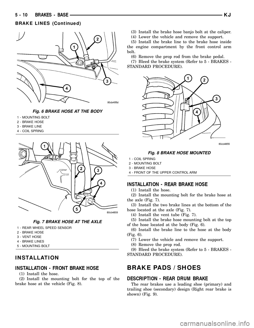
(3) Remove the brake line from the hose at the
body (Fig. 6).
(4) Remove the brake hose mounting bolt at the
top of the hose located at the body (Fig. 6).
(5) Remove the vent tube (Fig. 7).
(6) Remove the two brake lines at the bottom of
the hose located at the axle (Fig. 7).
(7) Remove the mounting bolt for the brake hose
at the axle (Fig. 7).
(8) Remove the hose.
Fig. 3 ISO Flaring
1 - ADAPTER
2 - LUBRICATE HERE
3 - PILOT
4 - FLUSH WITH BAR
5 - TUBING
6 - BAR ASSEMBLY
Fig. 4 INNER FENDER BRAKE LINE
1 - GROMMET
2 - BRAKE LINE
Fig. 5 FRONT BRAKE HOSE
1 - TOP OF FRONT BRAKE HOSE
2 - WHEEL SPEED SENSOR WIRE
3 - UPPER CONTROL ARM
KJBRAKES - BASE 5 - 9
BRAKE LINES (Continued)
Page 174 of 1803
INSTALLATION
INSTALLATION - FRONT BRAKE HOSE
(1) Install the hose.
(2) Install the mounting bolt for the top of the
brake hose at the vehicle (Fig. 8).(3) Install the brake hose banjo bolt at the caliper.
(4) Lower the vehicle and remove the support.
(5) Install the brake line to the brake hose inside
the engine compartment by the front control arm
bolt.
(6) Remove the prop rod from the brake pedal.
(7) Bleed the brake system (Refer to 5 - BRAKES -
STANDARD PROCEDURE).
INSTALLATION - REAR BRAKE HOSE
(1) Install the hose.
(2) Install the mounting bolt for the brake hose at
the axle (Fig. 7).
(3) Install the two brake lines at the bottom of the
hose located at the axle (Fig. 7).
(4) Install the vent tube (Fig. 7).
(5) Install the brake hose mounting bolt at the top
of the hose located at the body (Fig. 6).
(6) Install the brake line to the hose at the body
(Fig. 6).
(7) Lower the vehicle and remove the support.
(8) Remove the prop rod.
(9) Bleed the brake system (Refer to 5 - BRAKES -
STANDARD PROCEDURE).
BRAKE PADS / SHOES
DESCRIPTION - REAR DRUM BRAKE
The rear brakes use a leading shoe (primary) and
trailing shoe (secondary) design (Right rear brake is
shown) (Fig. 9).
Fig. 6 BRAKE HOSE AT THE BODY
1 - MOUNTING BOLT
2 - BRAKE HOSE
3 - BRAKE LINE
4 - COIL SPRING
Fig. 7 BRAKE HOSE AT THE AXLE
1 - REAR WHEEL SPEED SENSOR
2 - BRAKE HOSE
3 - VENT HOSE
4 - BRAKE LINES
5 - MOUNTING BOLT
Fig. 8 BRAKE HOSE MOUNTED
1 - COIL SPRING
2 - MOUNTING BOLT
3 - BRAKE HOSE
4 - FRONT OF THE UPPER CONTROL ARM
5 - 10 BRAKES - BASEKJ
BRAKE LINES (Continued)
Page 175 of 1803

OPERATION - REAR DRUM BRAKE
When the brake pedal is depressed hydraulic pres-
sure pushes the rear brake wheel cylinder pistons
outward. The wheel cylinder push rods then push the
brake shoes outward against the brake drum. When
the brake pedal is released return springs attached
to the brake shoes pull the shoes back to there orig-
inal position (Fig. 9).
REMOVAL
REMOVAL - FRONT BRAKE PADS
(1) Raise and support the vehicle.
(2) Remove the front wheel and tire assembly.
(3) Drain a small amount of fluid from the master
cylinder brake reservoir with acleansuction gun.(4) Bottom the caliper pistons into the caliper by
prying the caliper over.
(5) Remove the caliper mounting bolts.
(6) Remove the disc brake caliper from the mount.
CAUTION: Never allow the disc brake caliper to
hang from the brake hose. Damage to the brake
hose will result. Provide a suitable support to hang
the caliper securely.
(7) Remove the inboard and outboard pads.
REMOVAL - DRUM BRAKE SHOES
(1) Raise the vehicle and remove the rear wheels.
(2) Remove and discard the spring nuts securing
drums to wheel studs.
(3) Remove the brake drums. If drums prove diffi-
cult to remove, retract brake shoes. Remove the
access hole plug at the rear of backing plate and
back off adjuster screw with brake tool and screw-
driver.
(4) Clean the individual brake components, includ-
ing the support plate and wheel cylinder exterior,
with a find mist of water. Then wipe the brake com-
ponents clean with a dampened cloth.
(5) Remove the primary and secondary return
springs from anchor pin with the brake spring pliers.
(6) Remove the U-clip and washer securing
adjuster cable to the parking brake lever.
(7) Remove the hold-down springs, retainers and
pins with standard retaining spring tool.
(8) Remove the parking brake strut and cable
guide.
(9) Remove the adjuster lever, adjuster screw and
spring.
(10) Remove the adjuster cable.
(11) Remove the brake shoes.
(12) Disconnect the cable from the parking brake
lever and remove the lever ( if needed).
INSTALLATION
INSTALLATION - FRONT BRAKE PADS
(1) Install the inboard and outboard pads.
(2) Install the caliper (Refer to 5 - BRAKES/HY-
DRAULIC/MECHANICAL/DISC BRAKE CALIPERS
- INSTALLATION).
(3) Install the tire and wheel assembly. (Refer to
22 - TIRES/WHEELS/WHEELS - STANDARD PRO-
CEDURE).
INSTALLATION - DRUM BRAKE SHOES
Bonded linings should be replaced when worn to a
thickness of 1.6 mm (1/16 in.).
Fig. 9 BRAKE COMPONENTS
1 - SECONDARY SHOE
2 - SHOE GUIDE PLATE
3 - PRIMARY SHOE
4 - HORSE SHOE RETAINING CLIP
5 - PRIMARY RETURN SPRING
6 - PARK BRAKE STRUT
7 - HOLD DOWN SPRING AND RETAINERS
8 - SHOE RETURN SPRING
9 - ADJUSTER SCREW ASSEMBLY
10 - ADJUSTER LEVER
11 - ADJUSTER CABLE
12 - SECONDARY RETURN SPRING
13 - CABLE GUIDE
14 - WHEEL CYLINDER
15 - PARK BRAKE STRUT AND SPRING
16 - SUPPORT PLATE
KJBRAKES - BASE 5 - 11
BRAKE PADS / SHOES (Continued)
Page 176 of 1803

Examine the lining contact pattern to determine if
the shoes are bent or the drum is tapered. The lining
should exhibit contact across its entire width. Shoes
exhibiting contact only on one side should be
replaced and the drum checked for runout or taper.
Inspect the adjuster screw assembly. Replace the
assembly if the star wheel or threads are damaged,
or the components are severely rusted or corroded.
Discard the brake springs and retainer components
if worn, distorted or collapsed. Also replace the
springs if a brake drag condition had occurred. Over-
heating will distort and weaken the springs.
Inspect the brake shoe contact pads on the support
plate, replace the support plate if any of the pads are
worn or rusted through. Also replace the plate if it is
bent or distorted.
(1) Clean support plate with brake cleaner.
(2) If new drums are being installed, remove pro-
tective coating with carburetor cleaner followed by
final rinse with brake cleaner.
(3) Clean and lubricate anchor pin with light coat
of Mopar multi-mileage grease.
(4) Apply Mopar multi-mileage grease to brake
shoe contact surfaces of support plate (Fig. 10).
(5) Lubricate the adjuster screw threads and pivot
with spray lube.
(6) Attach parking brake lever to secondary brake
shoe. Use new washer and U-clip to secure lever.
(7) Attach the parking brake cable to lever (if
removed).
(8) Install the brake shoes on support plate.
Secure shoes with new hold-down springs, pins and
retainers.
(9) Install the parking brake strut and spring.(10) Install the guide plate and adjuster cable on
anchor pin.
(11) Install the adjuster cable guide on the shoe.
(12) Install the primary and secondary return
springs.
(13) Lubricate and assemble adjuster screw.
(14) Install the adjuster screw, spring and lever
and connect to adjuster cable.
(15) Adjust the shoes to the drum (Refer to 5 -
BRAKES/HYDRAULIC/MECHANICAL/BRAKE
PADS/SHOES - ADJUSTMENTS).
(16) Install the brake drum.
(17) Install the wheel/tire assemblies and lower
vehicle (Refer to 22 - TIRES/WHEELS/WHEELS -
STANDARD PROCEDURE).
(18) Verify firm brake pedal before moving vehicle.
ADJUSTMENTS
ADJUSTMENT - REAR DRUM BRAKE
The rear drum brakes are equipped with a self-ad-
justing mechanism. Under normal circumstances, the
only time adjustment is required is when the shoes
are replaced, removed for access to other parts, or
when one or both drums are replaced.
Adjustment can be made with a standard brake
gauge or with adjusting tool. Adjustment is per-
formed with the complete brake assembly installed
on the backing plate.
ADJUSTMENT WITH BRAKE GAUGE
(1) Be sure parking brakes are fully released.
(2) Raise rear of vehicle and remove wheels and
brake drums.
(3) Verify that left and right automatic adjuster
levers and cables are properly connected.
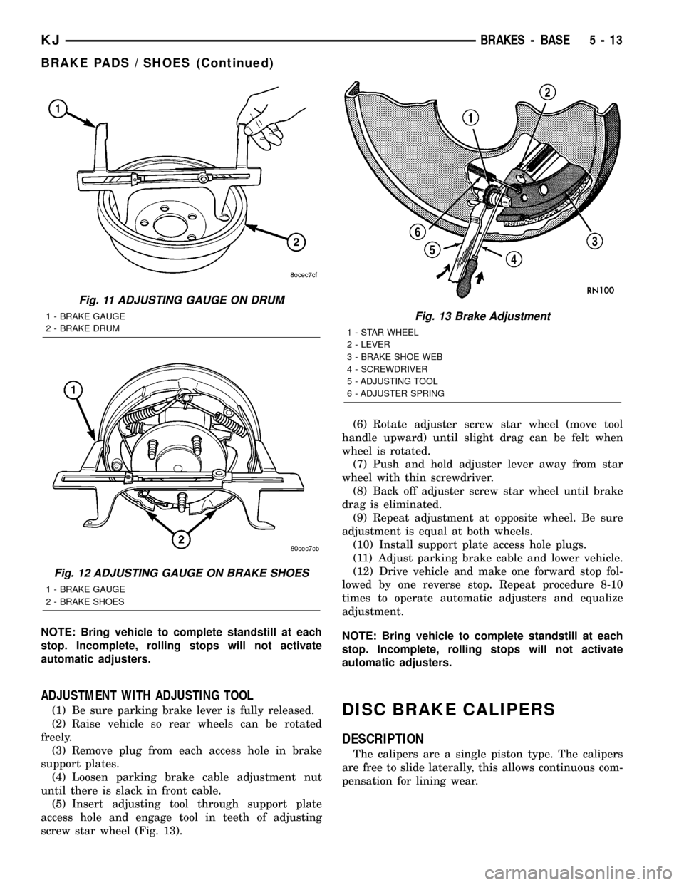
(4) Insert brake gauge in drum. Expand gauge
until gauge inner legs contact drum braking surface.
Then lock gauge in position (Fig. 11).
(5) Reverse gauge and install it on brake shoes.
Position gauge legs at shoe centers as shown (Fig.
12). If gauge does not fit (too loose/too tight), adjust
shoes.
(6) Pull shoe adjuster lever away from adjuster
screw star wheel.
(7) Turn adjuster screw star wheel (by hand) to
expand or retract brake shoes. Continue adjustment
until gauge outside legs are light drag-fit or 30 thou-
sands of an inch clearence on the shoes.
(8) Install brake drums and wheels and lower
vehicle.
(9) Drive vehicle and make one forward stop fol-
lowed by one reverse stop. Repeat procedure 8-10
times to operate automatic adjusters and equalize
adjustment.
Fig. 10 Shoe Contact Surfaces
1 - ANCHOR PIN
2 - SUPPORT PLATE
3 - SHOE CONTACT SURFACES
5 - 12 BRAKES - BASEKJ
BRAKE PADS / SHOES (Continued)
Page 177 of 1803
NOTE: Bring vehicle to complete standstill at each
stop. Incomplete, rolling stops will not activate
automatic adjusters.
ADJUSTMENT WITH ADJUSTING TOOL
(1) Be sure parking brake lever is fully released.
(2) Raise vehicle so rear wheels can be rotated
freely.
(3) Remove plug from each access hole in brake
support plates.
(4) Loosen parking brake cable adjustment nut
until there is slack in front cable.
(5) Insert adjusting tool through support plate
access hole and engage tool in teeth of adjusting
screw star wheel (Fig. 13).(6) Rotate adjuster screw star wheel (move tool
handle upward) until slight drag can be felt when
wheel is rotated.
(7) Push and hold adjuster lever away from star
wheel with thin screwdriver.
(8) Back off adjuster screw star wheel until brake
drag is eliminated.
(9) Repeat adjustment at opposite wheel. Be sure
adjustment is equal at both wheels.
(10) Install support plate access hole plugs.
(11) Adjust parking brake cable and lower vehicle.
(12) Drive vehicle and make one forward stop fol-
lowed by one reverse stop. Repeat procedure 8-10
times to operate automatic adjusters and equalize
adjustment.
NOTE: Bring vehicle to complete standstill at each
stop. Incomplete, rolling stops will not activate
automatic adjusters.DISC BRAKE CALIPERS
DESCRIPTION
The calipers are a single piston type. The calipers
are free to slide laterally, this allows continuous com-
pensation for lining wear.
Fig. 11 ADJUSTING GAUGE ON DRUM
1 - BRAKE GAUGE
2 - BRAKE DRUM
Fig. 12 ADJUSTING GAUGE ON BRAKE SHOES
1 - BRAKE GAUGE
2 - BRAKE SHOES
Fig. 13 Brake Adjustment
1 - STAR WHEEL
2 - LEVER
3 - BRAKE SHOE WEB
4 - SCREWDRIVER
5 - ADJUSTING TOOL
6 - ADJUSTER SPRING
KJBRAKES - BASE 5 - 13
BRAKE PADS / SHOES (Continued)
Page 178 of 1803

OPERATION
When the brakes are applied fluid pressure is
exerted against the caliper piston. The fluid pressure
is exerted equally and in all directions. This means
pressure exerted against the caliper piston and
within the caliper bore will be equal (Fig. 14).
Fluid pressure applied to the piston is transmitted
directly to the inboard brake shoe. This forces the
shoe lining against the inner surface of the disc
brake rotor. At the same time, fluid pressure within
the piston bore forces the caliper to slide inward on
the mounting bolts. This action brings the outboard
brake shoe lining into contact with the outer surface
of the disc brake rotor.
In summary, fluid pressure acting simultaneously
on both piston and caliper, produces a strong clamp-
ing action. When sufficient force is applied, friction
will attempt to stop the rotors from turning and
bring the vehicle to a stop.
Application and release of the brake pedal gener-
ates only a very slight movement of the caliper and
piston. Upon release of the pedal, the caliper and pis-
ton return to a rest position. The brake shoes do not
retract an appreciable distance from the rotor. In
fact, clearance is usually at, or close to zero. The rea-
sons for this are to keep road debris from gettingbetween the rotor and lining and in wiping the rotor
surface clear each revolution.
The caliper piston seal controls the amount of pis-
ton extension needed to compensate for normal lining
wear.
During brake application, the seal is deflected out-
ward by fluid pressure and piston movement (Fig.
15). When the brakes (and fluid pressure) are
released, the seal relaxes and retracts the piston.
The amount of piston retraction is determined by
the amount of seal deflection. Generally the amount
is just enough to maintain contact between the pis-
ton and inboard brake shoe.
REMOVAL
(1) Install prop rod on the brake pedal to keep
pressure on the brake system.
(2) Raise and support vehicle.
(3) Remove front wheel and tire assembly.
(4) Drain small amount of fluid from master cylin-
der brake reservoir with suction gun.
(5) Remove the brake hose banjo bolt if replacing
caliper (Fig. 16).
(6) Remove the caliper mounting slide pin bolts
(Fig. 16).
(7) Remove the caliper from vehicle.
DISASSEMBLY
(1) Remove brake shoes from caliper.
(2) Drain brake fluid out of caliper.
(3) Take a piece of wood and pad it with one-inch
thickness of shop towels. Place this piece in the out-
board shoe side of the caliper in front of the piston.
This will cushion and protect caliper piston during
removal (Fig. 17).
Fig. 14 Brake Caliper Operation
1 - CALIPER
2 - PISTON
3 - PISTON BORE
4 - SEAL
5 - INBOARD SHOE
6 - OUTBOARD SHOE
Fig. 15 Lining Wear Compensation By Piston Seal
1 - PISTON
2 - CYLINDER BORE
3 - PISTON SEAL BRAKE PRESSURE OFF
4 - CALIPER HOUSING
5 - DUST BOOT
6 - PISTON SEAL BRAKE PRESSURE ON
5 - 14 BRAKES - BASEKJ
DISC BRAKE CALIPERS (Continued)
Page 179 of 1803
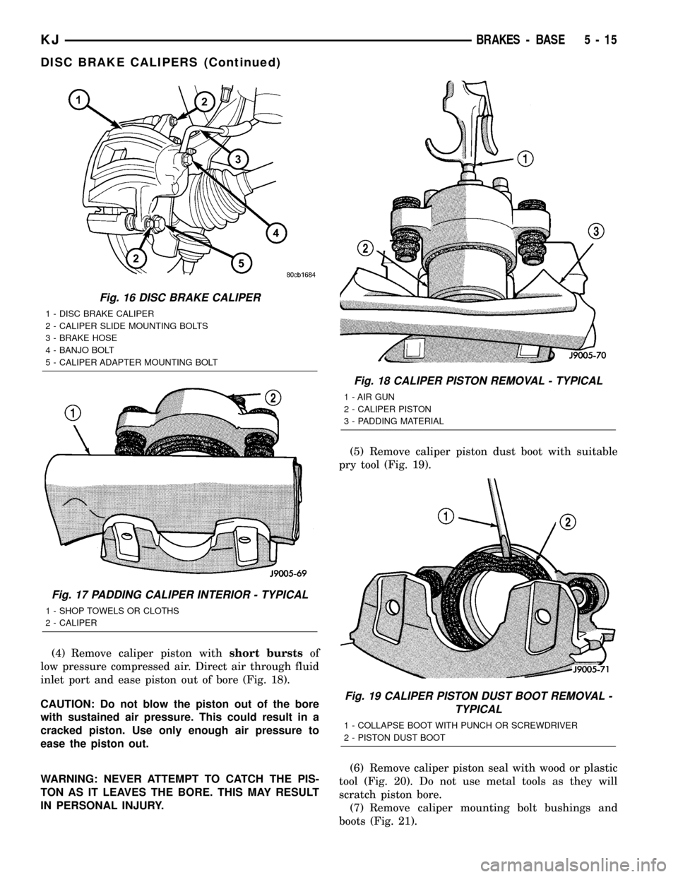
(4) Remove caliper piston withshort burstsof
low pressure compressed air. Direct air through fluid
inlet port and ease piston out of bore (Fig. 18).
CAUTION: Do not blow the piston out of the bore
with sustained air pressure. This could result in a
cracked piston. Use only enough air pressure to
ease the piston out.
WARNING: NEVER ATTEMPT TO CATCH THE PIS-
TON AS IT LEAVES THE BORE. THIS MAY RESULT
IN PERSONAL INJURY.(5) Remove caliper piston dust boot with suitable
pry tool (Fig. 19).
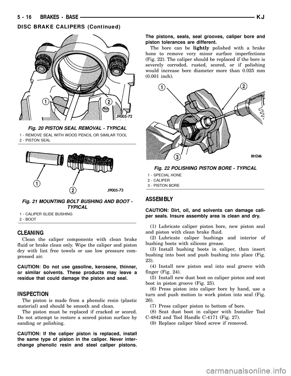
(6) Remove caliper piston seal with wood or plastic
tool (Fig. 20). Do not use metal tools as they will
scratch piston bore.
(7) Remove caliper mounting bolt bushings and
boots (Fig. 21).
Fig. 16 DISC BRAKE CALIPER
1 - DISC BRAKE CALIPER
2 - CALIPER SLIDE MOUNTING BOLTS
3 - BRAKE HOSE
4 - BANJO BOLT
5 - CALIPER ADAPTER MOUNTING BOLT
Fig. 17 PADDING CALIPER INTERIOR - TYPICAL
1 - SHOP TOWELS OR CLOTHS
2 - CALIPER
Fig. 18 CALIPER PISTON REMOVAL - TYPICAL
1 - AIR GUN
2 - CALIPER PISTON
3 - PADDING MATERIAL
Fig. 19 CALIPER PISTON DUST BOOT REMOVAL -
TYPICAL
1 - COLLAPSE BOOT WITH PUNCH OR SCREWDRIVER
2 - PISTON DUST BOOT
KJBRAKES - BASE 5 - 15
DISC BRAKE CALIPERS (Continued)
Page 180 of 1803
CLEANING
Clean the caliper components with clean brake
fluid or brake clean only. Wipe the caliper and piston
dry with lint free towels or use low pressure com-
pressed air.
CAUTION: Do not use gasoline, kerosene, thinner,
or similar solvents. These products may leave a
residue that could damage the piston and seal.
INSPECTION
The piston is made from a phenolic resin (plastic
material) and should be smooth and clean.
The piston must be replaced if cracked or scored.
Do not attempt to restore a scored piston surface by
sanding or polishing.
CAUTION: If the caliper piston is replaced, install
the same type of piston in the caliper. Never inter-
change phenolic resin and steel caliper pistons.The pistons, seals, seal grooves, caliper bore and
piston tolerances are different.
The bore can belightlypolished with a brake
hone to remove very minor surface imperfections
(Fig. 22). The caliper should be replaced if the bore is
severely corroded, rusted, scored, or if polishing
would increase bore diameter more than 0.025 mm
(0.001 inch).
ASSEMBLY
CAUTION: Dirt, oil, and solvents can damage cali-
per seals. Insure assembly area is clean and dry.
(1) Lubricate caliper piston bore, new piston seal
and piston with clean brake fluid.
(2) Lubricate caliper bushings and interior of
bushing boots with silicone grease.
(3) Install bushing boots in caliper, then insert
bushing into boot and push bushing into place (Fig.
23).
(4) Install new piston seal into seal groove with
finger (Fig. 24).
(5) Install new dust boot on caliper piston and seat
boot in piston groove (Fig. 25).
(6) Press piston into caliper bore by hand, use a
turn and push motion to work piston into seal (Fig.
26).
(7) Press caliper piston to bottom of bore.
(8) Seat dust boot in caliper with Installer Tool
C-4842 and Tool Handle C-4171 (Fig. 27).
(9) Replace caliper bleed screw if removed.
Fig. 20 PISTON SEAL REMOVAL - TYPICAL
1 - REMOVE SEAL WITH WOOD PENCIL OR SIMILAR TOOL
2 - PISTON SEAL
Fig. 21 MOUNTING BOLT BUSHING AND BOOT -
TYPICAL
1 - CALIPER SLIDE BUSHING
2 - BOOT
Fig. 22 POLISHING PISTON BORE - TYPICAL
1 - SPECIAL HONE
2 - CALIPER
3 - PISTON BORE
5 - 16 BRAKES - BASEKJ
DISC BRAKE CALIPERS (Continued)