Lines JEEP LIBERTY 2002 KJ / 1.G Repair Manual
[x] Cancel search | Manufacturer: JEEP, Model Year: 2002, Model line: LIBERTY, Model: JEEP LIBERTY 2002 KJ / 1.GPages: 1803, PDF Size: 62.3 MB
Page 1309 of 1803

NOTE: Plastigage is available in a variety of clear-
ance ranges. Use the most appropriate range for
the specifications you are checking.
(4) Install the proper crankshaft bearings to
achieve the specified bearing clearances. (Refer to 9 -
ENGINE/ENGINE BLOCK/CRANKSHAFT MAIN
BEARINGS - STANDARD PROCEDURE) (Refer to 9
- ENGINE/ENGINE BLOCK/CONNECTING ROD
BEARINGS - STANDARD PROCEDURE)
REMOVAL - ENGINE ASSEMBLY
(1) Disconnect the battery negative cable.
(2) Remove hood. Mark hood hinge location for
reinstallation.
(3) Remove air cleaner assembly.
(4) Remove radiator core support bracket.
(5) Remove fan shroud with electric fan assembly.
(6) Remove drive belt.
NOTE: It is NOT necessary to discharge the A/C
system to remove the engine.
(7) Remove A/C compressor and secure away from
engine with lines attached.
(8) Remove generator and secure away from
engine.
NOTE: Do NOT remove the phenolic pulley from the
P/S pump. It is not required for P/S pump removal.
(9) Remove power steering pump with lines
attached and secure away from engine.
(10) Drain cooling system.
(11) Remove coolant bottle.
(12) Disconnect the heater hoses from the engine.
(13) Disconnect heater hoses from heater core and
remove hose assembly.
(14) Disconnect throttle and speed control cables.
(15) Remove upper radiator hose from engine.
(16) Remove lower radiator hose from engine.
(17) Disconnect the engine to body ground straps
at the left side of cowl.
(18) Disconnect the engine wiring harness at the
following points:
²Intake air temperature (IAT) sensor
²Fuel Injectors
²Throttle Position (TPS) Switch
²Idle Air Control (IAC) Motor
²Engine Oil Pressure Switch
²Engine Coolant Temperature (ECT) Sensor
²Manifold Absolute Pressure MAP) Sensor
²Camshaft Position (CMP) Sensor
²Coil Over Plugs
²Crankshaft Position Sensor
(19) Remove coil over plugs.
(20) Release fuel rail pressure.(21) Remove fuel rail and secure away from
engine.
(22) Remove the PCV hose.
(23) Remove the breather hoses.
(24) Remove the vacuum hose for the power brake
booster.
(25) Disconnect knock sensors.
(26) Secure the left and right engine wiring har-
nesses away from engine.
(27) Raise vehicle.
(28) Disconnect oxygen sensor wiring.
(29) Disconnect crankshaft postion sensor.
(30) Disconnect the engine block heater power
cable, if equipped.
(31) Disconnect the front propshaft at the front
differential and secure out of way.
(32) Remove the starter.
(33) Remove the ground straps from the engine
(34) Disconnect the exhaust pipes at the manifold.
(35) Remove the structural cover, if equipped.
(36) Remove torque convertor bolts, and mark
location for reassembly.
(37) Remove transmission bellhousing to engine
bolts.
(38) Loosen left and right engine mount thru bolts.
NOTE: It is not necessary to completely remove
engine mount thru bolts, for engine removal.
(39) Lower the vehicle.
(40) Support the transmission with a suitable jack.
(41) Connect a suitable engine hoist to the engine.
CAUTION: The 2.4L engine with manual transmis-
sions, can be removed without removing the man-
ual transmission. Use caution when attempting this
procedure as the clearance is tight.
(42) Remove engine from vehicle.
INSTALLATION - ENGINE ASSEMBLY
(1) Position the engine in the vehicle.
CAUTION: Use caution when installing 2.4L engine
into vehicle equipped with manual transmission, as
clearance is tight.
(2) Install both left and right side engine mounts
into the frame mounts.
(3) Raise the vehicle.
(4) Install the transmission bellhousing to engine
mounting bolts. Tighten the bolts to 41 N´m (30ft.
lbs.).
(5) Tighten the engine mount thru bolts.
(6) Install the torque convertor bolts.
(7) Connect the ground straps on the left and right
side of the engine.
9s - 12 ENGINEKJ
ENGINE - 2.4L (Continued)
Page 1317 of 1803

Possible indications of the cylinder head gasket
leaking between a cylinder and an adjacent water
jacket are:
²Engine overheating
²Loss of coolant
²Excessive steam (white smoke) emitting from
exhaust
²Coolant foaming
CYLINDER-TO-CYLINDER LEAKAGE TEST
To determine if an engine cylinder head gasket is
leaking between adjacent cylinders, follow the proce-
dures in Cylinder Compression Pressure Test (Refer
to 9 - ENGINE - DIAGNOSIS AND TESTING). An
engine cylinder head gasket leaking between adja-
cent cylinders will result in approximately a 50±70%
reduction in compression pressure.
CYLINDER-TO-WATER JACKET LEAKAGE TEST
WARNING: USE EXTREME CAUTION WHEN THE
ENGINE IS OPERATING WITH COOLANT PRES-
SURE CAP REMOVED.
VISUAL TEST METHOD
With the engine cool, remove the coolant pressure
cap. Start the engine and allow it to warm up until
thermostat opens.
If a large combustion/compression pressure leak
exists, bubbles will be visible in the coolant.
COOLING SYSTEM TESTER METHOD
WARNING: WITH COOLING SYSTEM TESTER IN
PLACE, PRESSURE WILL BUILD UP FAST. EXCES-
SIVE PRESSURE BUILT UP, BY CONTINUOUS
ENGINE OPERATION, MUST BE RELEASED TO A
SAFE PRESSURE POINT. NEVER PERMIT PRES-
SURE TO EXCEED 138 kPa (20 psi).
Install Cooling System Tester 7700 or equivalent to
pressure cap neck. Start the engine and observe the
tester's pressure gauge. If gauge pulsates with every
power stroke of a cylinder a combustion pressure
leak is evident.
CHEMICAL TEST METHOD
Combustion leaks into the cooling system can also
be checked by using Bloc-Chek Kit C-3685-A or
equivalent. Perform test following the procedures
supplied with the tool kit.
REMOVAL - CYLINDER HEAD
(1) Perform fuel system pressure release procedure
before attempting any repairs.(Refer to 14 -FUEL SYSTEM/FUEL DELIVERY - SPECIFICA-
TIONS)
(2) Disconnect battery negative cable.
(3) Drain cooling system. (Refer to 7 - COOLING -
STANDARD PROCEDURE)
(4) Remove air filter housing and inlet tube.
(5) Remove intake manifold.
(6) Remove heater tube support bracket from cyl-
inder head.
(7) Disconnect radiator upper and heater supply
hoses from water outlet connections.
(8) Remove accessory drive belts. (Refer to 7 -
COOLING/ACCESSORY DRIVE/DRIVE BELTS -
REMOVAL)
(9) Raise vehicle and remove exhaust pipe from
manifold.
(10) Remove power steering pump and set aside.
Do not disconnect lines.
(11) Remove accessory drive bracket
(12) Remove ignition coil and wires from engine.
(13) Disconnect cam sensor and fuel injector wir-
ing connectors.
(14) Remove timing belt and camshaft sprockets.
(Refer to 9 - ENGINE/VALVE TIMING/TIMING
BELT/CHAIN AND SPROCKETS - REMOVAL)
(15) Remove timing belt idler pulley and rear tim-
ing belt cover. (Refer to 9 - ENGINE/VALVE TIM-
ING/TIMING BELT / CHAIN COVER(S) -
REMOVAL)
(16) Remove cylinder head cover. (Refer to 9 -
ENGINE/CYLINDER HEAD/CYLINDER HEAD
COVER(S) - REMOVAL)
(17) Remove camshafts (Refer to 9 - ENGINE/
CYLINDER HEAD/CAMSHAFT(S) - REMOVAL).
NOTE: Identify rocker arm position to ensure cor-
rect re-installation in original position, if reused.
(18) Remove rocker arms. (Refer to 9 - ENGINE/
CYLINDER HEAD/ROCKER ARMS - REMOVAL).
(19) Remove cylinder head bolts in REVERSE
sequence of tightening.
(20) Remove cylinder head from engine block.
(21) Inspect and clean cylinder head. (Refer to 9 -
ENGINE/CYLINDER HEAD - INSPECTION) (Refer
to 9 - ENGINE/CYLINDER HEAD - CLEANING)
CLEANING
To ensure engine gasket sealing, proper surface
preparation must be performed, especially with the
use of aluminum engine components and multi-layer
steel cylinder head gaskets.
NOTE: Multi-Layer Steel (MLS) head gaskets require
a scratch free sealing surface.
9s - 20 ENGINEKJ
CYLINDER HEAD (Continued)
Page 1319 of 1803
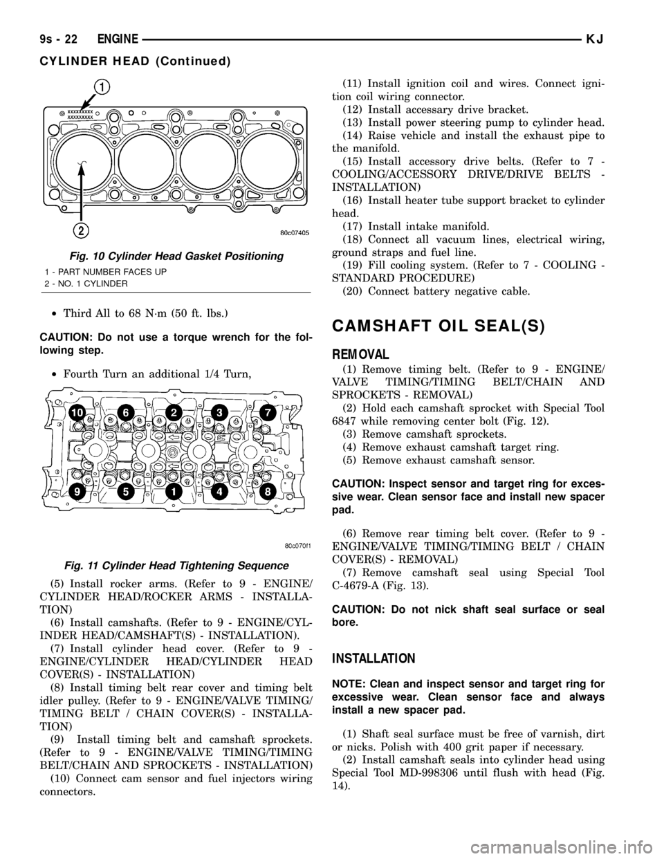
²Third All to 68 N´m (50 ft. lbs.)
CAUTION: Do not use a torque wrench for the fol-
lowing step.
²Fourth Turn an additional 1/4 Turn,
(5) Install rocker arms. (Refer to 9 - ENGINE/
CYLINDER HEAD/ROCKER ARMS - INSTALLA-
TION)
(6) Install camshafts. (Refer to 9 - ENGINE/CYL-
INDER HEAD/CAMSHAFT(S) - INSTALLATION).
(7) Install cylinder head cover. (Refer to 9 -
ENGINE/CYLINDER HEAD/CYLINDER HEAD
COVER(S) - INSTALLATION)
(8) Install timing belt rear cover and timing belt
idler pulley. (Refer to 9 - ENGINE/VALVE TIMING/
TIMING BELT / CHAIN COVER(S) - INSTALLA-
TION)
(9) Install timing belt and camshaft sprockets.
(Refer to 9 - ENGINE/VALVE TIMING/TIMING
BELT/CHAIN AND SPROCKETS - INSTALLATION)
(10) Connect cam sensor and fuel injectors wiring
connectors.(11) Install ignition coil and wires. Connect igni-
tion coil wiring connector.
(12) Install accessary drive bracket.
(13) Install power steering pump to cylinder head.
(14) Raise vehicle and install the exhaust pipe to
the manifold.
(15) Install accessory drive belts. (Refer to 7 -
COOLING/ACCESSORY DRIVE/DRIVE BELTS -
INSTALLATION)
(16) Install heater tube support bracket to cylinder
head.
(17) Install intake manifold.
(18) Connect all vacuum lines, electrical wiring,
ground straps and fuel line.
(19) Fill cooling system. (Refer to 7 - COOLING -
STANDARD PROCEDURE)
(20) Connect battery negative cable.
CAMSHAFT OIL SEAL(S)
REMOVAL
(1) Remove timing belt. (Refer to 9 - ENGINE/
VALVE TIMING/TIMING BELT/CHAIN AND
SPROCKETS - REMOVAL)
(2) Hold each camshaft sprocket with Special Tool
6847 while removing center bolt (Fig. 12).
(3) Remove camshaft sprockets.
(4) Remove exhaust camshaft target ring.
(5) Remove exhaust camshaft sensor.
CAUTION: Inspect sensor and target ring for exces-
sive wear. Clean sensor face and install new spacer
pad.
(6) Remove rear timing belt cover. (Refer to 9 -
ENGINE/VALVE TIMING/TIMING BELT / CHAIN
COVER(S) - REMOVAL)
(7) Remove camshaft seal using Special Tool
C-4679-A (Fig. 13).
CAUTION: Do not nick shaft seal surface or seal
bore.
INSTALLATION
NOTE: Clean and inspect sensor and target ring for
excessive wear. Clean sensor face and always
install a new spacer pad.
(1) Shaft seal surface must be free of varnish, dirt
or nicks. Polish with 400 grit paper if necessary.
(2) Install camshaft seals into cylinder head using
Special Tool MD-998306 until flush with head (Fig.
14).
Fig. 10 Cylinder Head Gasket Positioning
1 - PART NUMBER FACES UP
2 - NO. 1 CYLINDER
Fig. 11 Cylinder Head Tightening Sequence
9s - 22 ENGINEKJ
CYLINDER HEAD (Continued)
Page 1349 of 1803

(2) Spray a small stream of water (Spray Bottle) at
the suspected leak area.
(3) If engine RPM'S change, the area of the sus-
pected leak has been found.
(4) Repair as required.
REMOVAL
(1) Disconnect negative cable from battery.
(2) Disconnect connector from inlet air tempera-
ture sensor.
(3) Disconnect air intake tube at throttle body and
remove upper air cleaner housing.
(4) Disconnect connector from throttle position
sensor (TPS).
(5) Disconnect connector from idle air control (IAC)
motor.
(6) Disconnect connector from MAP sensor.
(7) Remove vacuum lines for purge solenoid and
PCV valve at intake manifold.
(8) Remove vacuum lines for power brake booster,
LDP, EGR transducer, and speed control vacuum res-
ervoir (if equipped) at intake manifold fittings.
(9) Disconnect throttle, speed control (if equipped),
and transaxle control (if equipped) and cables from
throttle lever and bracket. (Refer to 14 - FUEL SYS-
TEM/FUEL INJECTION/THROTTLE CONTROL
CABLE - REMOVAL)
(10) Perform fuel system pressure release proce-
durebefore attempting any repairs.(Refer to 14 -
FUEL SYSTEM/FUEL DELIVERY - STANDARD
PROCEDURE)
(11) Disconnect fuel line. (Refer to 14 - FUEL SYS-
TEM/FUEL DELIVERY/QUICK CONNECT FIT-
TING - STANDARD PROCEDURE)
(12) Disconnect coolant temperature sensor/fuel
injector wire harness connector.
(13) Disconnect fuel injector harness.
(14) Remove intake manifold to cylinder head fas-
teners.
(15) Remove the manifold from engine.
CAUTION: Cover intake manifold openings to pre-
vent foreign material from entering engine.
(16) Inspect the manifold. (Refer to 9 - ENGINE/
MANIFOLDS/INTAKE MANIFOLD - INSPECTION)
INSPECTION
(1) Check manifold surfaces for flatness with
straight edge. Surface must be flat within 0.15 mm
per 300 mm (0.006 in. per foot) of manifold length.
(2) Inspect manifold for cracks or distortion.
Replace manifold if necessary.
INSTALLATION
(1) Clean manifold sealing surfaces.
(2) Install new manifold to cylinder head seals.
(3) Install manifold to head.
(4) Install and tighten intake manifold fasteners to
28 N´m (250 in. lbs.) in the sequence shown (Fig. 90).
Repeat procedure until all bolts are at specified
torque.
(5) Install throttle cables in bracket.
(6) Connect throttle, speed control, (if equipped),
cables to throttle lever.
(7) Connect vacuum lines for power brake booster,
LDP, EGR transducer, and speed control vacuum res-
ervoir (if equipped) at upper intake manifold fittings.
(8) Connect vacuum lines for purge solenoid and
PCV valve.
(9) Connect electrical connectors for MAP sensor,
throttle position sensor (TPS), and idle air control
(IAC) motor.
(10) Connect the fuel line. (Refer to 14 - FUEL
SYSTEM/FUEL DELIVERY/QUICK CONNECT FIT-
TING - STANDARD PROCEDURE)
(11) Connect coolant temperature sensor/fuel injec-
tor wiring harness electrical connector.
(12) Install the air cleaner housing and air intake
tube to throttle body.
(13) Connect inlet air temperature sensor connec-
tor.
(14) Connect negative cable to battery.
Fig. 90 LOWER INTAKE MANIFOLD TIGHTENING
SEQUENCE
9s - 52 ENGINEKJ
INTAKE MANIFOLD (Continued)
Page 1363 of 1803
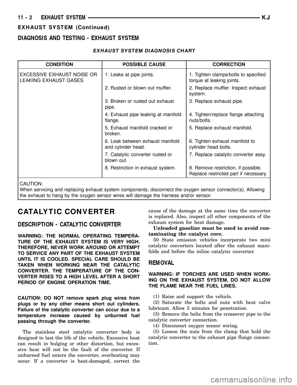
DIAGNOSIS AND TESTING - EXHAUST SYSTEM
EXHAUST SYSTEM DIAGNOSIS CHART
CONDITION POSSIBLE CAUSE CORRECTION
EXCESSIVE EXHAUST NOISE OR
LEAKING EXHAUST GASES1. Leaks at pipe joints. 1. Tighten clamps/bolts to specified
torque at leaking joints.
2. Rusted or blown out muffler. 2. Replace muffler. Inspect exhaust
system.
3. Broken or rusted out exhaust
pipe.3. Replace exhaust pipe.
4. Exhaust pipe leaking at manifold
flange.4. Tighten/replace flange attaching
nuts/bolts.
5. Exhaust manifold cracked or
broken.5. Replace exhaust manifold.
6. Leak between exhaust manifold
and cylinder head.6. Tighten exhaust manifold to
cylinder head bolts.
7. Catalytic converter rusted or
blown out.7. Replace catalytic converter assy.
8. Restriction in exhaust system. 8. Remove restriction, if possible.
Replace restricted part if necessary.
CAUTION:
When servicing and replacing exhaust system components, disconnect the oxygen sensor connector(s). Allowing
the exhaust to hang by the oxygen sensor wires will damage the harness and/or sensor.
CATALYTIC CONVERTER
DESCRIPTION - CATALYTIC CONVERTER
WARNING: THE NORMAL OPERATING TEMPERA-
TURE OF THE EXHAUST SYSTEM IS VERY HIGH.
THEREFORE, NEVER WORK AROUND OR ATTEMPT
TO SERVICE ANY PART OF THE EXHAUST SYSTEM
UNTIL IT IS COOLED. SPECIAL CARE SHOULD BE
TAKEN WHEN WORKING NEAR THE CATALYTIC
CONVERTER. THE TEMPERATURE OF THE CON-
VERTER RISES TO A HIGH LEVEL AFTER A SHORT
PERIOD OF ENGINE OPERATION TIME.
CAUTION: DO NOT remove spark plug wires from
plugs or by any other means short out cylinders.
Failure of the catalytic converter can occur due to a
temperature increase caused by unburned fuel
passing through the converter.
The stainless steel catalytic converter body is
designed to last the life of the vehicle. Excessive heat
can result in bulging or other distortion, but exces-
sive heat will not be the fault of the converter. If
unburned fuel enters the converter, overheating may
occur. If a converter is heat-damaged, correct thecause of the damage at the same time the converter
is replaced. Also, inspect all other components of the
exhaust system for heat damage.
Unleaded gasoline must be used to avoid con-
taminating the catalyst core.
50 State emission vehicles incorporate two mini
catalytic converters located after the exhaust mani-
folds and before the inline catalytic converter.
REMOVAL
WARNING: IF TORCHES ARE USED WHEN WORK-
ING ON THE EXHAUST SYSTEM, DO NOT ALLOW
THE FLAME NEAR THE FUEL LINES.
(1) Raise and support the vehicle.
(2) Saturate the bolts and nuts with heat valve
lubricant. Allow 5 minutes for penetration.
(3) Remove the bolts from the crossover pipe to the
catalytic converter connection.
(4) Disconnect oxygen sensor wiring.
(5) Loosen the nuts from the clamp that hold the
catalytic converter to the exhaust pipe flange connec-
tion.
11 - 2 EXHAUST SYSTEMKJ
EXHAUST SYSTEM (Continued)
Page 1364 of 1803
NOTE: Do not remove nut from T-Bolt. Only remove
nut far enough, so that the T end can be removed
from the clamp.
(6) Remove the T bolt end of the fastener, from the
clamp.
(7) Spread the clamp, and remove the catalytic
converter from the vehicle.
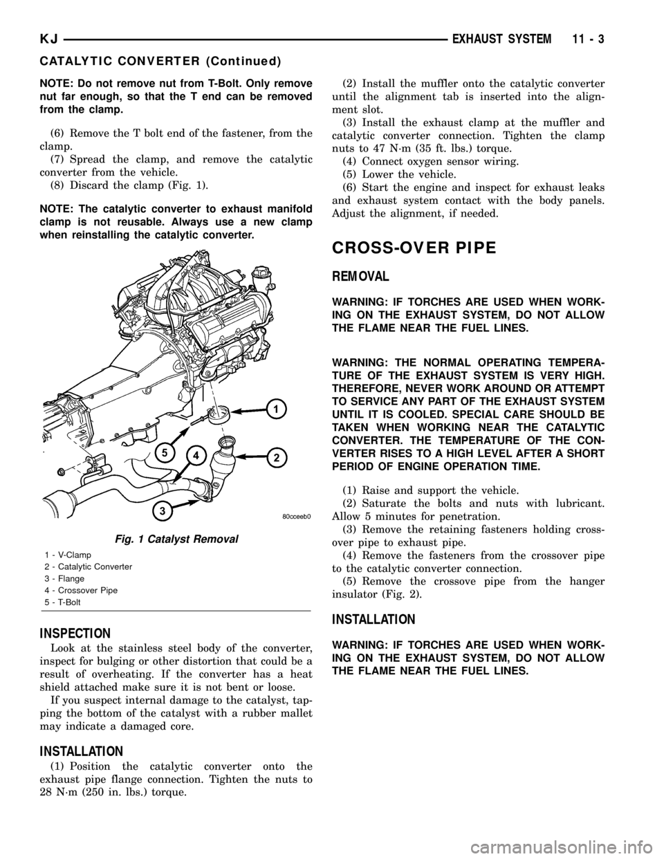
(8) Discard the clamp (Fig. 1).
NOTE: The catalytic converter to exhaust manifold
clamp is not reusable. Always use a new clamp
when reinstalling the catalytic converter.
INSPECTION
Look at the stainless steel body of the converter,
inspect for bulging or other distortion that could be a
result of overheating. If the converter has a heat
shield attached make sure it is not bent or loose.
If you suspect internal damage to the catalyst, tap-
ping the bottom of the catalyst with a rubber mallet
may indicate a damaged core.
INSTALLATION
(1) Position the catalytic converter onto the
exhaust pipe flange connection. Tighten the nuts to
28 N´m (250 in. lbs.) torque.(2) Install the muffler onto the catalytic converter
until the alignment tab is inserted into the align-
ment slot.
(3) Install the exhaust clamp at the muffler and
catalytic converter connection. Tighten the clamp
nuts to 47 N´m (35 ft. lbs.) torque.
(4) Connect oxygen sensor wiring.
(5) Lower the vehicle.
(6) Start the engine and inspect for exhaust leaks
and exhaust system contact with the body panels.
Adjust the alignment, if needed.
CROSS-OVER PIPE
REMOVAL
WARNING: IF TORCHES ARE USED WHEN WORK-
ING ON THE EXHAUST SYSTEM, DO NOT ALLOW
THE FLAME NEAR THE FUEL LINES.
WARNING: THE NORMAL OPERATING TEMPERA-
TURE OF THE EXHAUST SYSTEM IS VERY HIGH.
THEREFORE, NEVER WORK AROUND OR ATTEMPT
TO SERVICE ANY PART OF THE EXHAUST SYSTEM
UNTIL IT IS COOLED. SPECIAL CARE SHOULD BE
TAKEN WHEN WORKING NEAR THE CATALYTIC
CONVERTER. THE TEMPERATURE OF THE CON-
VERTER RISES TO A HIGH LEVEL AFTER A SHORT
PERIOD OF ENGINE OPERATION TIME.
(1) Raise and support the vehicle.
(2) Saturate the bolts and nuts with lubricant.
Allow 5 minutes for penetration.
(3) Remove the retaining fasteners holding cross-
over pipe to exhaust pipe.
(4) Remove the fasteners from the crossover pipe
to the catalytic converter connection.
(5) Remove the crossove pipe from the hanger
insulator (Fig. 2).
INSTALLATION
WARNING: IF TORCHES ARE USED WHEN WORK-
ING ON THE EXHAUST SYSTEM, DO NOT ALLOW
THE FLAME NEAR THE FUEL LINES.
Fig. 1 Catalyst Removal
1 - V-Clamp
2 - Catalytic Converter
3 - Flange
4 - Crossover Pipe
5 - T-Bolt
KJEXHAUST SYSTEM 11 - 3
CATALYTIC CONVERTER (Continued)
Page 1369 of 1803
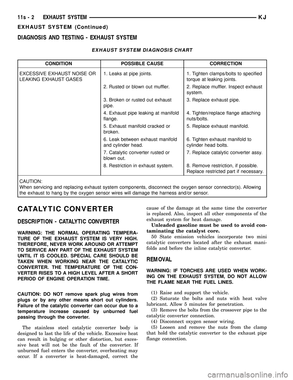
DIAGNOSIS AND TESTING - EXHAUST SYSTEM
EXHAUST SYSTEM DIAGNOSIS CHART
CONDITION POSSIBLE CAUSE CORRECTION
EXCESSIVE EXHAUST NOISE OR
LEAKING EXHAUST GASES1. Leaks at pipe joints. 1. Tighten clamps/bolts to specified
torque at leaking joints.
2. Rusted or blown out muffler. 2. Replace muffler. Inspect exhaust
system.
3. Broken or rusted out exhaust
pipe.3. Replace exhaust pipe.
4. Exhaust pipe leaking at manifold
flange.4. Tighten/replace flange attaching
nuts/bolts.
5. Exhaust manifold cracked or
broken.5. Replace exhaust manifold.
6. Leak between exhaust manifold
and cylinder head.6. Tighten exhaust manifold to
cylinder head bolts.
7. Catalytic converter rusted or
blown out.7. Replace catalytic converter assy.
8. Restriction in exhaust system. 8. Remove restriction, if possible.
Replace restricted part if necessary.
CAUTION:
When servicing and replacing exhaust system components, disconnect the oxygen sensor connector(s). Allowing
the exhaust to hang by the oxygen sensor wires will damage the harness and/or sensor.
CATALYTIC CONVERTER
DESCRIPTION - CATALYTIC CONVERTER
WARNING: THE NORMAL OPERATING TEMPERA-
TURE OF THE EXHAUST SYSTEM IS VERY HIGH.
THEREFORE, NEVER WORK AROUND OR ATTEMPT
TO SERVICE ANY PART OF THE EXHAUST SYSTEM
UNTIL IT IS COOLED. SPECIAL CARE SHOULD BE
TAKEN WHEN WORKING NEAR THE CATALYTIC
CONVERTER. THE TEMPERATURE OF THE CON-
VERTER RISES TO A HIGH LEVEL AFTER A SHORT
PERIOD OF ENGINE OPERATION TIME.
CAUTION: DO NOT remove spark plug wires from
plugs or by any other means short out cylinders.
Failure of the catalytic converter can occur due to a
temperature increase caused by unburned fuel
passing through the converter.
The stainless steel catalytic converter body is
designed to last the life of the vehicle. Excessive heat
can result in bulging or other distortion, but exces-
sive heat will not be the fault of the converter. If
unburned fuel enters the converter, overheating may
occur. If a converter is heat-damaged, correct thecause of the damage at the same time the converter
is replaced. Also, inspect all other components of the
exhaust system for heat damage.
Unleaded gasoline must be used to avoid con-
taminating the catalyst core.
50 State emission vehicles incorporate two mini
catalytic converters located after the exhaust mani-
folds and before the inline catalytic converter.
REMOVAL
WARNING: IF TORCHES ARE USED WHEN WORK-
ING ON THE EXHAUST SYSTEM, DO NOT ALLOW
THE FLAME NEAR THE FUEL LINES.
(1) Raise and support the vehicle.
(2) Saturate the bolts and nuts with heat valve
lubricant. Allow 5 minutes for penetration.
(3) Remove the bolts from the crossover pipe to the
catalytic converter connection.
(4) Disconnect oxygen sensor wiring.
(5) Loosen and remove the nuts from the clamp
that hold the catalytic converter to the exhaust pipe
flange connection.
11s - 2 EXHAUST SYSTEMKJ
EXHAUST SYSTEM (Continued)
Page 1371 of 1803
CROSS-OVER PIPE
REMOVAL
WARNING: IF TORCHES ARE USED WHEN WORK-
ING ON THE EXHAUST SYSTEM, DO NOT ALLOW
THE FLAME NEAR THE FUEL LINES.
WARNING: THE NORMAL OPERATING TEMPERA-
TURE OF THE EXHAUST SYSTEM IS VERY HIGH.
THEREFORE, NEVER WORK AROUND OR ATTEMPT
TO SERVICE ANY PART OF THE EXHAUST SYSTEM
UNTIL IT IS COOLED. SPECIAL CARE SHOULD BE
TAKEN WHEN WORKING NEAR THE CATALYTIC
CONVERTER. THE TEMPERATURE OF THE CON-
VERTER RISES TO A HIGH LEVEL AFTER A SHORT
PERIOD OF ENGINE OPERATION TIME.
(1) Raise and support the vehicle.
(2) Saturate the bolts and nuts with lubricant.
Allow 5 minutes for penetration.
(3) Remove the retaining fasteners holding cross-
over pipe to exhaust pipe.
(4) Remove the fasteners from the crossover pipe
to the catalytic converter connection.
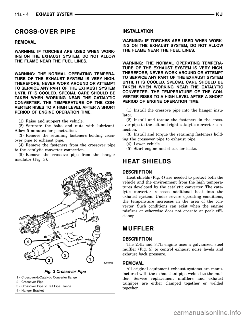
(5) Remove the crossove pipe from the hanger
insulator (Fig. 3).
INSTALLATION
WARNING: IF TORCHES ARE USED WHEN WORK-
ING ON THE EXHAUST SYSTEM, DO NOT ALLOW
THE FLAME NEAR THE FUEL LINES.
WARNING: THE NORMAL OPERATING TEMPERA-
TURE OF THE EXHAUST SYSTEM IS VERY HIGH.
THEREFORE, NEVER WORK AROUND OR ATTEMPT
TO SERVICE ANY PART OF THE EXHAUST SYSTEM
UNTIL IT IS COOLED. SPECIAL CARE SHOULD BE
TAKEN WHEN WORKING NEAR THE CATALYTIC
CONVERTER. THE TEMPERATURE OF THE CON-
VERTER RISES TO A HIGH LEVEL AFTER A SHORT
PERIOD OF ENGINE OPERATION TIME.
(1) Install the crossove pipe into the hanger insu-
lator.
(2) Install and torque the fasteners in the cross-
over pipe to the left and right catalytic converter con-
nection.
(3) Install and torque the retaining fasteners hold-
ing the crossover pipe to exhaust pipe.
(4) Lower vehicle..
(5) Start engine and check for leaks.
HEAT SHIELDS
DESCRIPTION
Heat shields (Fig. 4) are needed to protect both the
vehicle and the environment from the high tempera-
tures developed by the catalytic converter. The cata-
lytic converter releases additional heat into the
exhaust system. Under severe operating conditions,
the temperature increases in the area of the con-
verter. Such conditions can exist when the engine
misfires or otherwise does not operate at peak effi-
ciency.
MUFFLER
DESCRIPTION
The 2.4L and 3.7L engine uses a galvanized steel
muffler (Fig. 5) to control exhaust noise levels and
exhaust back pressure.
REMOVAL
All original equipment exhaust systems are manu-
factured with the exhaust tailpipe welded to the muf-
fler. Service replacement mufflers and exhaust
tailpipes are either clamped together or welded
together.Fig. 3 Crossover Pipe
1 - Crossover-toCatalytic Converter flange
2 - Crossover Pipe
3 - Crossover Pipe to Tail Pipe Flange
4 - Hanger Bracket
11s - 4 EXHAUST SYSTEMKJ
Page 1383 of 1803
FUEL SYSTEM
TABLE OF CONTENTS
page page
FUEL DELIVERY..........................1FUEL INJECTION........................29
FUEL DELIVERY
TABLE OF CONTENTS
page page
FUEL DELIVERY
DESCRIPTION..........................2
OPERATION............................3
DIAGNOSIS AND TESTING - FUEL
PRESSURE LEAK DOWN TEST...........3
STANDARD PROCEDURE - FUEL SYSTEM
PRESSURE RELEASE...................4
SPECIFICATIONS
FUEL SYSTEM PRESSURE..............5
TORQUE.............................5
SPECIAL TOOLS
FUEL SYSTEM........................6
FLOW MANAGEMENT VALVE
DESCRIPTION..........................6
OPERATION............................6
REMOVAL.............................6
INSTALLATION..........................7
FUEL FILTER
DESCRIPTION..........................7
REMOVAL.............................7
INSTALLATION..........................8
FUEL LEVEL SENDING UNIT / SENSOR
DESCRIPTION..........................9
OPERATION............................9
DIAGNOSIS AND TESTING - FUEL LEVEL
SENDING UNIT........................9
REMOVAL.............................9
INSTALLATION.........................10
FUEL LINES
DESCRIPTION.........................10
QUICK CONNECT FITTING
DESCRIPTION.........................10
STANDARD PROCEDURE - QUICK-CONNECT
FITTINGS...........................10
FUEL PRESSURE REGULATOR
DESCRIPTION.........................13OPERATION...........................14
REMOVAL.............................14
INSTALLATION.........................14
FUEL PUMP
DESCRIPTION.........................15
OPERATION...........................15
DIAGNOSIS AND TESTING
DIAGNOSIS AND TESTING - FUEL PUMP
CAPACITY TEST......................15
DIAGNOSIS AND TESTING - FUEL PUMP
PRESSURE TEST.....................15
DIAGNOSIS AND TESTING - FUEL PUMP
AMPERAGE TEST.....................16
FUEL PUMP MODULE
DESCRIPTION.........................18
OPERATION...........................18
REMOVAL.............................18
INSTALLATION.........................19
FUEL RAIL
DESCRIPTION.........................21
OPERATION...........................21
REMOVAL.............................22
INSTALLATION.........................24
FUEL TANK
DESCRIPTION.........................24
OPERATION...........................24
REMOVAL.............................25
INSTALLATION.........................27
FUEL TANK CHECK VALVE
DESCRIPTION.........................28
OPERATION...........................28
REMOVAL.............................28
INSTALLATION.........................28
INLET FILTER
REMOVAL.............................28
INSTALLATION.........................28
KJFUEL SYSTEM 14 - 1
Page 1384 of 1803
FUEL DELIVERY
DESCRIPTION
The fuel delivery system consists of:
²the 2±section fuel pump module containing the
electric fuel pump, fuel pressure regulator, fuel gauge
sending unit (fuel level sensor) and a fuel filter
located inside the lower section of pump module
²fuel tubes/lines/hoses
²A separately mounted main fuel filter²quick-connect fittings
²fuel injector rail
²fuel tank
²fuel tank filler/vent tube assembly
²fuel tank filler tube cap
²accelerator pedal
²throttle cable
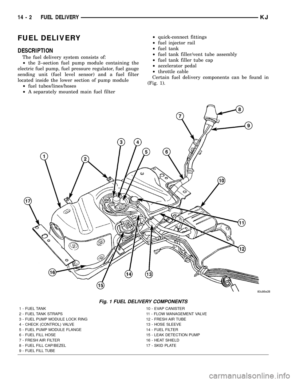
Certain fuel delivery components can be found in
(Fig. 1).
Fig. 1 FUEL DELIVERY COMPONENTS
1 - FUEL TANK 10 - EVAP CANISTER
2 - FUEL TANK STRAPS 11 - FLOW MANAGEMENT VALVE
3 - FUEL PUMP MODULE LOCK RING 12 - FRESH AIR TUBE
4 - CHECK (CONTROL) VALVE 13 - HOSE SLEEVE
5 - FUEL PUMP MODULE FLANGE 14 - FUEL FILTER
6 - FUEL FILL HOSE 15 - LEAK DETECTION PUMP
7 - FRESH AIR FILTER 16 - HEAT SHIELD
8 - FUEL FILL CAP/BEZEL 17 - SKID PLATE
9 - FUEL FILL TUBE
14 - 2 FUEL DELIVERYKJ