air condition JEEP LIBERTY 2002 KJ / 1.G Repair Manual
[x] Cancel search | Manufacturer: JEEP, Model Year: 2002, Model line: LIBERTY, Model: JEEP LIBERTY 2002 KJ / 1.GPages: 1803, PDF Size: 62.3 MB
Page 312 of 1803
²Battery voltage
²Engine coolant temperature sensor
²Crankshaft position sensor
²Intake manifold air temperature sensor
²Manifold absolute pressure (MAP) sensor
²Throttle position sensor (TPS)
²Camshaft position sensor signal
²Park/neutral switch (gear indicator signalÐauto.
trans. only)
²Oxygen (O2S) sensors
Based on these inputs, the following occurs:
²Voltage is applied to the fuel injectors with the
ASD relay via the PCM. The PCM will then adjust
the injector pulse width by turning the ground circuit
to each individual injector on and off.
²The PCM monitors the O2S sensor input and
adjusts air-fuel ratio. It also adjusts engine idle
speed through the idle air control (IAC) motor.
²The PCM adjusts ignition timing by turning the
ground path to the coil(s) on and off.
²The PCM operates the A/C compressor clutch
through the clutch relay. This happens if A/C has
been selected by the vehicle operator and requested
by the A/C thermostat.
ACCELERATION MODE
This is an Open Loop mode. The PCM recognizes
an abrupt increase in throttle position or MAP pres-
sure as a demand for increased engine output and
vehicle acceleration. The PCM increases injector
pulse width in response to increased throttle opening.
DECELERATION MODE
When the engine is at operating temperature, this
is an Open Loop mode. During hard deceleration, the
PCM receives the following inputs.
²Air conditioning select signal (if equipped)
²Air conditioning request signal (if equipped)
²Battery voltage
²Engine coolant temperature sensor
²Crankshaft position sensor
²Intake manifold air temperature sensor
²Manifold absolute pressure (MAP) sensor
²Throttle position sensor (TPS)
²Camshaft position sensor signal
²Park/neutral switch (gear indicator signalÐauto.
trans. only)
²Vehicle speed
If the vehicle is under hard deceleration with the
proper rpm and closed throttle conditions, the PCM
will ignore the oxygen sensor input signal. The PCM
will enter a fuel cut-off strategy in which it will not
supply a ground to the injectors. If a hard decelera-
tion does not exist, the PCM will determine the
proper injector pulse width and continue injection.Based on the above inputs, the PCM will adjust
engine idle speed through the idle air control (IAC)
motor.
The PCM adjusts ignition timing by turning the
ground path to the coil on and off.
WIDE OPEN THROTTLE MODE
This is an Open Loop mode. During wide open
throttle operation, the PCM receives the following
inputs.
²Battery voltage
²Crankshaft position sensor
²Engine coolant temperature sensor
²Intake manifold air temperature sensor
²Manifold absolute pressure (MAP) sensor
²Throttle position sensor (TPS)
²Camshaft position sensor signal
During wide open throttle conditions, the following
occurs:
²Voltage is applied to the fuel injectors with the
ASD relay via the PCM. The PCM will then control
the injection sequence and injector pulse width by
turning the ground circuit to each individual injector
on and off. The PCM ignores the oxygen sensor input
signal and provides a predetermined amount of addi-
tional fuel. This is done by adjusting injector pulse
width.
²The PCM adjusts ignition timing by turning the
ground path to the coil(s) on and off.
IGNITION SWITCH OFF MODE
When ignition switch is turned to OFF position,
the PCM stops operating the injectors, ignition coil,
ASD relay and fuel pump relay.
DESCRIPTION - 5 VOLT SUPPLIES
Two different Powertrain Control Module (PCM)
five volt supply circuits are used; primary and sec-
ondary.
DESCRIPTION - IGNITION CIRCUIT SENSE
This circuit ties the ignition switch to the Power-
train Control Module (PCM).
DESCRIPTION - POWER GROUNDS
The Powertrain Control Module (PCM) has 2 main
grounds. Both of these grounds are referred to as
power grounds. All of the high-current, noisy, electri-
cal devices are connected to these grounds as well as
all of the sensor returns. The sensor return comes
into the sensor return circuit, passes through noise
suppression, and is then connected to the power
ground.
The power ground is used to control ground cir-
cuits for the following PCM loads:
²Generator field winding
KJELECTRONIC CONTROL MODULES 8E - 13
POWERTRAIN CONTROL MODULE (Continued)
Page 313 of 1803
²Fuel injectors
²Ignition coil(s)
²Certain relays/solenoids
²Certain sensors
DESCRIPTION - SENSOR RETURN
The Sensor Return circuits are internal to the Pow-
ertrain Control Module (PCM).
Sensor Return provides a low±noise ground refer-
ence for all engine control system sensors. Refer to
Power Grounds for more information.
OPERATION
OPERATION - PCM
The PCM operates the fuel system. The PCM is a
pre-programmed, triple microprocessor digital com-
puter. It regulates ignition timing, air-fuel ratio,
emission control devices, charging system, certain
transmission features, speed control, air conditioning
compressor clutch engagement and idle speed. The
PCM can adapt its programming to meet changing
operating conditions.
The PCM receives input signals from various
switches and sensors. Based on these inputs, the
PCM regulates various engine and vehicle operations
through different system components. These compo-
nents are referred to as Powertrain Control Module
(PCM) Outputs. The sensors and switches that pro-
vide inputs to the PCM are considered Powertrain
Control Module (PCM) Inputs.
The PCM adjusts ignition timing based upon
inputs it receives from sensors that react to: engine
rpm, manifold absolute pressure, engine coolant tem-
perature, throttle position, transmission gear selec-
tion (automatic transmission), vehicle speed, power
steering pump pressure, and the brake switch.
The PCM adjusts idle speed based on inputs it
receives from sensors that react to: throttle position,
vehicle speed, transmission gear selection, engine
coolant temperature and from inputs it receives from
the air conditioning clutch switch and brake switch.
Based on inputs that it receives, the PCM adjusts
ignition coil dwell. The PCM also adjusts the gener-
ator charge rate through control of the generator
field and provides speed control operation.
NOTE: PCM Inputs:
²A/C request (if equipped with factory A/C)
²A/C select (if equipped with factory A/C)
²A/C pressure transducer
²Auto shutdown (ASD) sense
²Battery temperature
²Battery voltage
²Brake switch²J1850 bus (+) circuits
²J1850 bus (-) circuits
²Camshaft position sensor signal
²Crankshaft position sensor
²Data link connection for DRB scan tool
²Engine coolant temperature sensor
²Fuel level (through J1850 circuitry)
²Generator (battery voltage) output
²Ignition circuit sense (ignition switch in on/off/
crank/run position)
²Intake manifold air temperature sensor
²Knock sensors (2 on 3.7L engine)
²Leak detection pump (switch) sense (if equipped)
²Manifold absolute pressure (MAP) sensor
²Oil pressure
²Oxygen sensors
²Park/neutral switch (auto. trans. only)
²Power ground
²Power steering pressure switch
²Sensor return
²Signal ground
²Speed control multiplexed single wire input
²Throttle position sensor
²Transfer case switch (4WD range position)
²Vehicle speed sensor
NOTE: PCM Outputs:
²A/C clutch relay
²Auto shutdown (ASD) relay
²J1850 bus (+/-) circuits for: speedometer, voltme-
ter, fuel gauge, oil pressure gauge/lamp, engine temp.
gauge and speed control warn. lamp
²Clutch pedal position switch override relay
²Data link connection for DRB scan tool
²EGR valve control solenoid (if equipped)
²EVAP canister purge solenoid
²Five volt sensor supply (primary)
²Five volt sensor supply (secondary)
²Fuel injectors
²Fuel pump relay
²Generator field driver (-)
²Generator field driver (+)
²Idle air control (IAC) motor
²Ignition coil(s)
²Leak detection pump (if equipped)
²Malfunction indicator lamp (Check engine lamp).
Driven through J1850 circuits.
²Oxygen sensor heater relays
²Oxygen sensors (pulse width modulated)
²Radiator cooling fan relay (pulse width modu-
lated)
²Speed control vacuum solenoid
²Speed control vent solenoid
²Tachometer (if equipped). Driven through J1850
circuits.
8E - 14 ELECTRONIC CONTROL MODULESKJ
POWERTRAIN CONTROL MODULE (Continued)
Page 315 of 1803
lock cylinder housing and is concealed beneath the
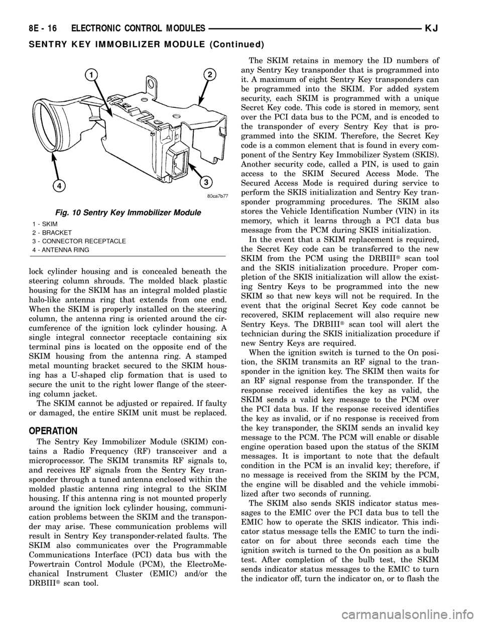
steering column shrouds. The molded black plastic
housing for the SKIM has an integral molded plastic
halo-like antenna ring that extends from one end.
When the SKIM is properly installed on the steering
column, the antenna ring is oriented around the cir-
cumference of the ignition lock cylinder housing. A
single integral connector receptacle containing six
terminal pins is located on the opposite end of the
SKIM housing from the antenna ring. A stamped
metal mounting bracket secured to the SKIM hous-
ing has a U-shaped clip formation that is used to
secure the unit to the right lower flange of the steer-
ing column jacket.
The SKIM cannot be adjusted or repaired. If faulty
or damaged, the entire SKIM unit must be replaced.
OPERATION
The Sentry Key Immobilizer Module (SKIM) con-
tains a Radio Frequency (RF) transceiver and a
microprocessor. The SKIM transmits RF signals to,
and receives RF signals from the Sentry Key tran-
sponder through a tuned antenna enclosed within the
molded plastic antenna ring integral to the SKIM
housing. If this antenna ring is not mounted properly
around the ignition lock cylinder housing, communi-
cation problems between the SKIM and the transpon-
der may arise. These communication problems will
result in Sentry Key transponder-related faults. The
SKIM also communicates over the Programmable
Communications Interface (PCI) data bus with the
Powertrain Control Module (PCM), the ElectroMe-
chanical Instrument Cluster (EMIC) and/or the
DRBIIItscan tool.The SKIM retains in memory the ID numbers of
any Sentry Key transponder that is programmed into
it. A maximum of eight Sentry Key transponders can
be programmed into the SKIM. For added system
security, each SKIM is programmed with a unique
Secret Key code. This code is stored in memory, sent
over the PCI data bus to the PCM, and is encoded to
the transponder of every Sentry Key that is pro-
grammed into the SKIM. Therefore, the Secret Key
code is a common element that is found in every com-
ponent of the Sentry Key Immobilizer System (SKIS).
Another security code, called a PIN, is used to gain
access to the SKIM Secured Access Mode. The
Secured Access Mode is required during service to
perform the SKIS initialization and Sentry Key tran-
sponder programming procedures. The SKIM also
stores the Vehicle Identification Number (VIN) in its
memory, which it learns through a PCI data bus
message from the PCM during SKIS initialization.
In the event that a SKIM replacement is required,
the Secret Key code can be transferred to the new
SKIM from the PCM using the DRBIIItscan tool
and the SKIS initialization procedure. Proper com-
pletion of the SKIS initialization will allow the exist-
ing Sentry Keys to be programmed into the new
SKIM so that new keys will not be required. In the
event that the original Secret Key code cannot be
recovered, SKIM replacement will also require new
Sentry Keys. The DRBIIItscan tool will alert the
technician during the SKIS initialization procedure if
new Sentry Keys are required.
When the ignition switch is turned to the On posi-
tion, the SKIM transmits an RF signal to the tran-
sponder in the ignition key. The SKIM then waits for
an RF signal response from the transponder. If the
response received identifies the key as valid, the
SKIM sends a valid key message to the PCM over
the PCI data bus. If the response received identifies
the key as invalid, or if no response is received from
the key transponder, the SKIM sends an invalid key
message to the PCM. The PCM will enable or disable
engine operation based upon the status of the SKIM
messages. It is important to note that the default
condition in the PCM is an invalid key; therefore, if
no message is received from the SKIM by the PCM,
the engine will be disabled and the vehicle immobi-
lized after two seconds of running.
The SKIM also sends SKIS indicator status mes-
sages to the EMIC over the PCI data bus to tell the
EMIC how to operate the SKIS indicator. This indi-
cator status message tells the EMIC to turn the indi-
cator on for about three seconds each time the
ignition switch is turned to the On position as a bulb
test. After completion of the bulb test, the SKIM
sends indicator status messages to the EMIC to turn
the indicator off, turn the indicator on, or to flash the
Fig. 10 Sentry Key Immobilizer Module
1 - SKIM
2 - BRACKET
3 - CONNECTOR RECEPTACLE
4 - ANTENNA RING
8E - 16 ELECTRONIC CONTROL MODULESKJ
SENTRY KEY IMMOBILIZER MODULE (Continued)
Page 320 of 1803
Schedule Condition Expected Operation
OverheatOil temperature above 240É F or
engine coolant temperature above
244É F- Delayed 2-3 upshift
- Delayed 3-4 upshift
- 3rd gear FEMCC from 30-48 mph
- 3rd gear PEMCC above 35 mph
- Above 25 mph the torque
converter will not unlock unless the
throttle is closed or if a wide open
throttle 2nd PEMCC to 1 kickdown
is made
STANDARD PROCEDURE - TCM QUICK LEARN
The quick learn procedure requires the use of the
DRBtscan tool.
This program allows the electronic transmission
system to recalibrate itself. This will provide the
proper transmission operation. The quick learn pro-
cedure should be performed if any of the following
procedures are performed:
²Transmission Assembly Replacement
²Transmission Control Module Replacement
²Solenoid Pack Replacement
²Clutch Plate and/or Seal Replacement
²Valve Body Replacement or Recondition
To perform the Quick Learn Procedure, the follow-
ing conditions must be met:
²The brakes must be applied
²The engine speed must be above 500 rpm
²The throttle angle (TPS) must be less than 3
degrees
²The shift lever position must stay in PARK until
prompted to shift to overdrive
²The shift lever position must stay in overdrive
after the Shift to Overdrive prompt until the DRBt
indicates the procedure is complete
²The calculated oil temperature must be above
60É and below 200É
HEATED SEAT MODULE
DESCRIPTION
The heated seat module is also known as the Seat
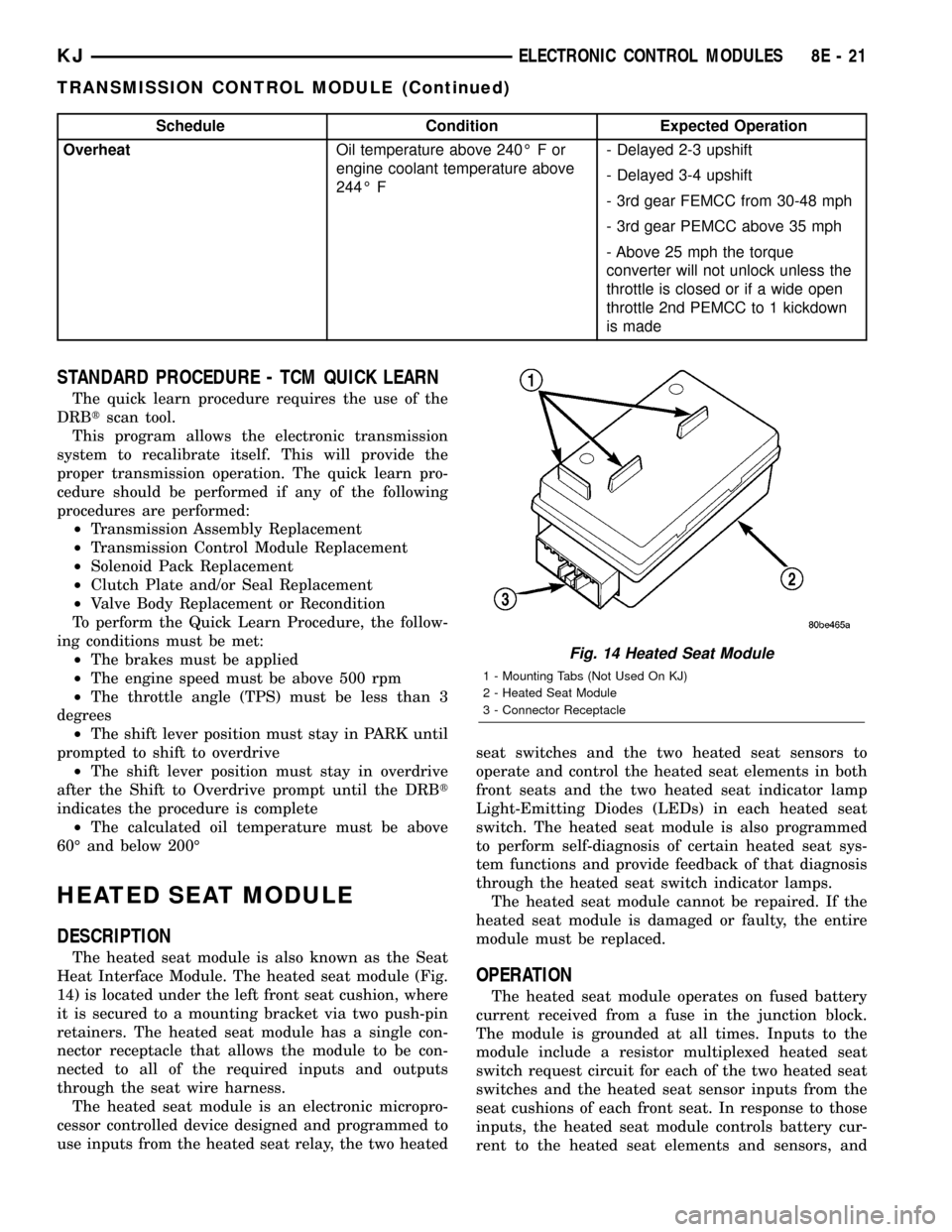
Heat Interface Module. The heated seat module (Fig.
14) is located under the left front seat cushion, where
it is secured to a mounting bracket via two push-pin
retainers. The heated seat module has a single con-
nector receptacle that allows the module to be con-
nected to all of the required inputs and outputs
through the seat wire harness.
The heated seat module is an electronic micropro-
cessor controlled device designed and programmed to
use inputs from the heated seat relay, the two heatedseat switches and the two heated seat sensors to
operate and control the heated seat elements in both
front seats and the two heated seat indicator lamp
Light-Emitting Diodes (LEDs) in each heated seat
switch. The heated seat module is also programmed
to perform self-diagnosis of certain heated seat sys-
tem functions and provide feedback of that diagnosis
through the heated seat switch indicator lamps.
The heated seat module cannot be repaired. If the
heated seat module is damaged or faulty, the entire
module must be replaced.
OPERATION
The heated seat module operates on fused battery
current received from a fuse in the junction block.
The module is grounded at all times. Inputs to the
module include a resistor multiplexed heated seat
switch request circuit for each of the two heated seat
switches and the heated seat sensor inputs from the
seat cushions of each front seat. In response to those
inputs, the heated seat module controls battery cur-
rent to the heated seat elements and sensors, and
Fig. 14 Heated Seat Module
1 - Mounting Tabs (Not Used On KJ)
2 - Heated Seat Module
3 - Connector Receptacle
KJELECTRONIC CONTROL MODULES 8E - 21
TRANSMISSION CONTROL MODULE (Continued)
Page 326 of 1803
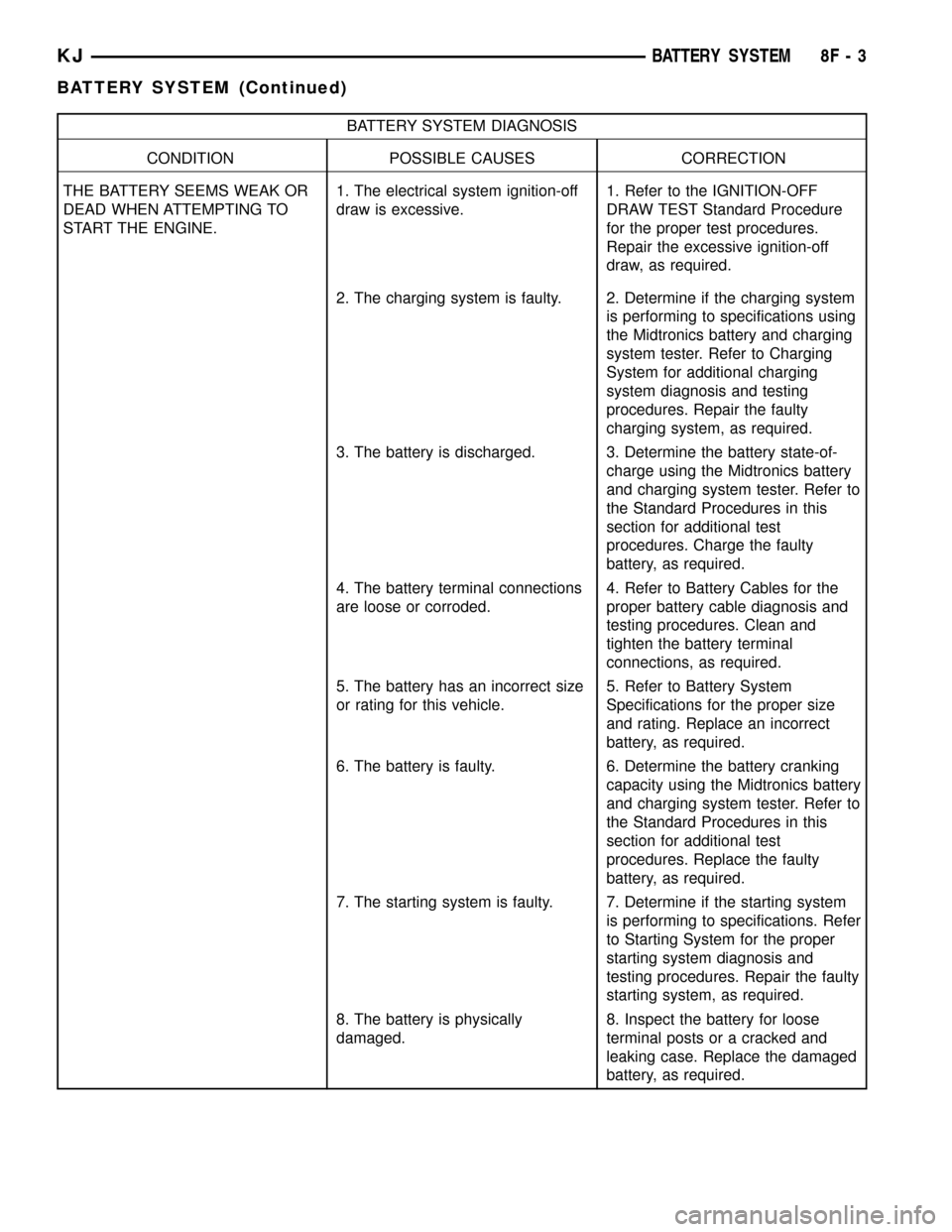
BATTERY SYSTEM DIAGNOSIS
CONDITION POSSIBLE CAUSES CORRECTION
THE BATTERY SEEMS WEAK OR
DEAD WHEN ATTEMPTING TO
START THE ENGINE.1. The electrical system ignition-off
draw is excessive.1. Refer to the IGNITION-OFF
DRAW TEST Standard Procedure
for the proper test procedures.
Repair the excessive ignition-off
draw, as required.
2. The charging system is faulty. 2. Determine if the charging system
is performing to specifications using
the Midtronics battery and charging
system tester. Refer to Charging
System for additional charging
system diagnosis and testing
procedures. Repair the faulty
charging system, as required.
3. The battery is discharged. 3. Determine the battery state-of-
charge using the Midtronics battery
and charging system tester. Refer to
the Standard Procedures in this
section for additional test
procedures. Charge the faulty
battery, as required.
4. The battery terminal connections
are loose or corroded.4. Refer to Battery Cables for the
proper battery cable diagnosis and
testing procedures. Clean and
tighten the battery terminal
connections, as required.
5. The battery has an incorrect size
or rating for this vehicle.5. Refer to Battery System
Specifications for the proper size
and rating. Replace an incorrect
battery, as required.
6. The battery is faulty. 6. Determine the battery cranking
capacity using the Midtronics battery
and charging system tester. Refer to
the Standard Procedures in this
section for additional test
procedures. Replace the faulty
battery, as required.
7. The starting system is faulty. 7. Determine if the starting system
is performing to specifications. Refer
to Starting System for the proper
starting system diagnosis and
testing procedures. Repair the faulty
starting system, as required.
8. The battery is physically
damaged.8. Inspect the battery for loose
terminal posts or a cracked and
leaking case. Replace the damaged
battery, as required.
KJBATTERY SYSTEM 8F - 3
BATTERY SYSTEM (Continued)
Page 327 of 1803
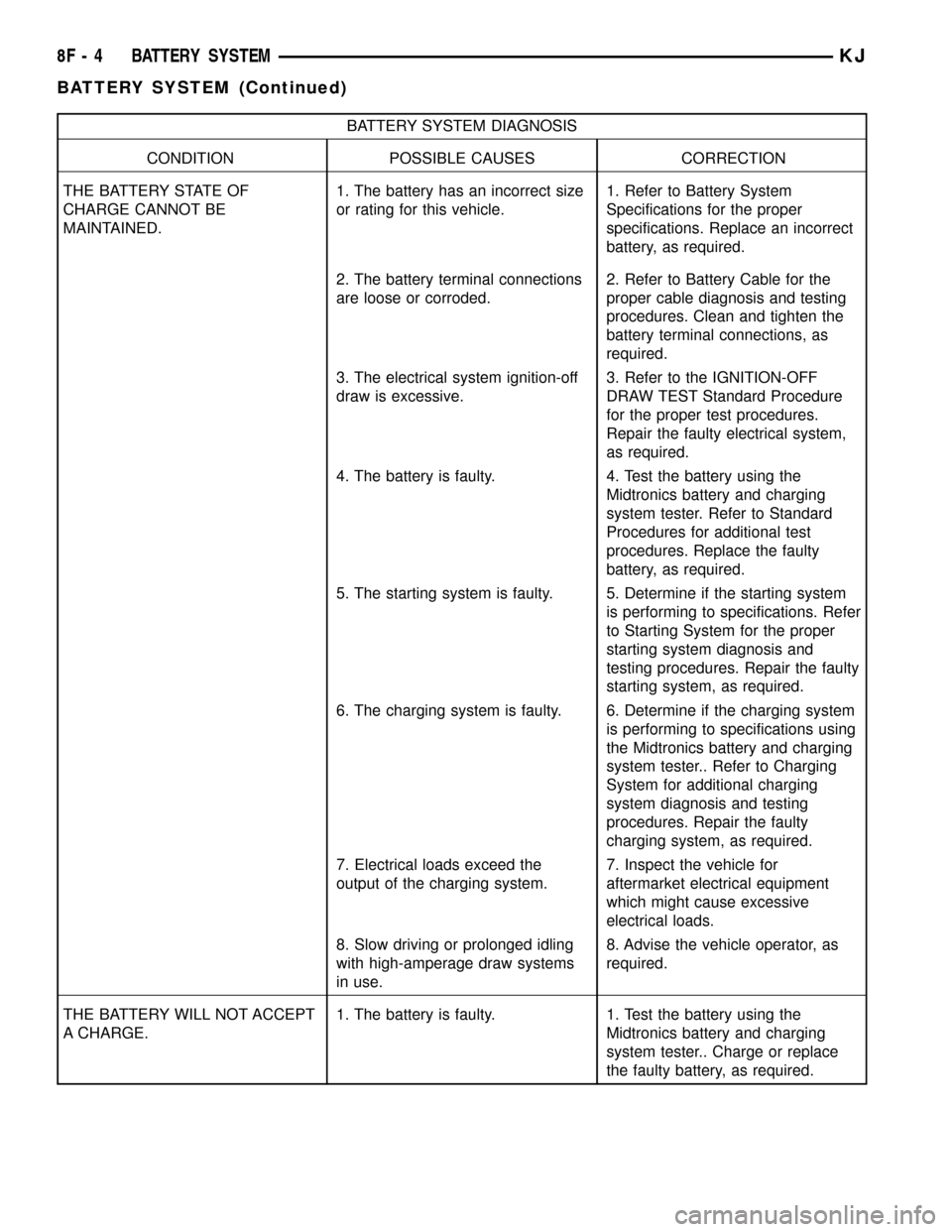
BATTERY SYSTEM DIAGNOSIS
CONDITION POSSIBLE CAUSES CORRECTION
THE BATTERY STATE OF
CHARGE CANNOT BE
MAINTAINED.1. The battery has an incorrect size
or rating for this vehicle.1. Refer to Battery System
Specifications for the proper
specifications. Replace an incorrect
battery, as required.
2. The battery terminal connections
are loose or corroded.2. Refer to Battery Cable for the
proper cable diagnosis and testing
procedures. Clean and tighten the
battery terminal connections, as
required.
3. The electrical system ignition-off
draw is excessive.3. Refer to the IGNITION-OFF
DRAW TEST Standard Procedure
for the proper test procedures.
Repair the faulty electrical system,
as required.
4. The battery is faulty. 4. Test the battery using the
Midtronics battery and charging
system tester. Refer to Standard
Procedures for additional test
procedures. Replace the faulty
battery, as required.
5. The starting system is faulty. 5. Determine if the starting system
is performing to specifications. Refer
to Starting System for the proper
starting system diagnosis and
testing procedures. Repair the faulty
starting system, as required.
6. The charging system is faulty. 6. Determine if the charging system
is performing to specifications using
the Midtronics battery and charging
system tester.. Refer to Charging
System for additional charging
system diagnosis and testing
procedures. Repair the faulty
charging system, as required.
7. Electrical loads exceed the
output of the charging system.7. Inspect the vehicle for
aftermarket electrical equipment
which might cause excessive
electrical loads.
8. Slow driving or prolonged idling
with high-amperage draw systems
in use.8. Advise the vehicle operator, as
required.
THE BATTERY WILL NOT ACCEPT
A CHARGE.1. The battery is faulty. 1. Test the battery using the
Midtronics battery and charging
system tester.. Charge or replace
the faulty battery, as required.
8F - 4 BATTERY SYSTEMKJ
BATTERY SYSTEM (Continued)
Page 346 of 1803
²the voltmeter (if equipped) does not register
properly
²an undercharged or overcharged battery condi-
tion occurs.
Remember that an undercharged battery is often
caused by:
²accessories being left on with the engine not
running
²a faulty or improperly adjusted switch that
allows a lamp to stay on. Refer to Ignition-Off Draw
Test in 8, Battery for more information.
INSPECTION
The Powertrain Control Module (PCM) monitors
critical input and output circuits of the charging sys-
tem, making sure they are operational. A Diagnostic
Trouble Code (DTC) is assigned to each input and
output circuit monitored by the On-Board Diagnostic
(OBD) system. Some charging system circuits are
checked continuously, and some are checked only
under certain conditions.
Refer to Diagnostic Trouble Codes in; Powertrain
Control Module; Electronic Control Modules for more
DTC information. This will include a complete list of
DTC's including DTC's for the charging system.
To perform a complete test of the charging system,
refer to the appropriate Powertrain Diagnostic Proce-
dures service manual and the DRBtscan tool. Per-form the following inspections before attaching the
scan tool.
(1) Inspect the battery condition. Refer to 8, Bat-
tery for procedures.
(2) Inspect condition of battery cable terminals,
battery posts, connections at engine block, starter
solenoid and relay. They should be clean and tight.
Repair as required.
(3) Inspect all fuses in both the fuseblock and
Power Distribution Center (PDC) for tightness in
receptacles. They should be properly installed and
tight. Repair or replace as required.
(4) Inspect generator mounting bolts for tightness.
Replace or tighten bolts if required. Refer to the Gen-
erator Removal/Installation section of this group for
torque specifications.
(5) Inspect generator drive belt condition and ten-
sion. Tighten or replace belt as required. Refer to
Belt Tension Specifications in 7, Cooling System.
(6) Inspect automatic belt tensioner (if equipped).
Refer to 7, Cooling System for information.
(7) Inspect generator electrical connections at gen-
erator field, battery output, and ground terminal (if
equipped). Also check generator ground wire connec-
tion at engine (if equipped). They should all be clean
and tight. Repair as required.
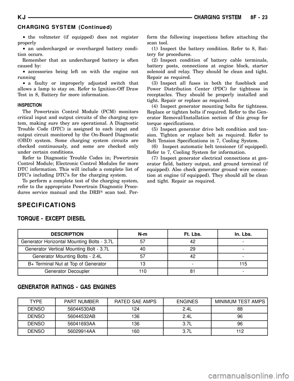
SPECIFICATIONS
TORQUE - EXCEPT DIESEL
DESCRIPTION N-m Ft. Lbs. In. Lbs.
Generator Horizontal Mounting Bolts - 3.7L 57 42 -
Generator Vertical Mounting Bolt - 3.7L 40 29 -
Generator Mounting Bolts - 2.4L 57 42 -
B+ Terminal Nut at Top of Generator 13 - 115
Generator Decoupler 110 81 -
GENERATOR RATINGS - GAS ENGINES
TYPE PART NUMBER RATED SAE AMPS ENGINES MINIMUM TEST AMPS
DENSO 56044530AB 124 2.4L 88
DENSO 56044532AB 136 2.4L 96
DENSO 56041693AA 136 3.7L 96
DENSO 56029914AA 160 3.7L 112
KJCHARGING SYSTEM 8F - 23
CHARGING SYSTEM (Continued)
Page 356 of 1803
If the vehicle is equipped with an automatic trans-
mission, battery voltage is supplied through the low-
amperage control circuit to the coil battery terminal
of the starter relay when the ignition switch is
turned to the momentary Start position. The park/
neutral position switch is installed in series between
the starter relay coil ground terminal and ground.
This normally open switch prevents the starter relay
from being energized and the starter motor from
operating unless the automatic transmission gear
selector is in the Neutral or Park positions.
When the starter relay coil is energized, the nor-
mally open relay contacts close. The relay contacts
connect the relay common feed terminal to the relay
normally open terminal. The closed relay contacts
energize the starter solenoid coil windings.
The energized solenoid pull-in coil pulls in the sole-
noid plunger. The solenoid plunger pulls the shift
lever in the starter motor. This engages the starter
overrunning clutch and pinion gear with the starter
ring gear on the manual transmission flywheel or on
the automatic transmission torque converter or
torque converter drive plate.
As the solenoid plunger reaches the end of its
travel, the solenoid contact disc completes the high-
amperage starter feed circuit and energizes the sole-
noid plunger hold-in coil. Current now flows betweenthe solenoid battery terminal and the starter motor,
energizing the starter.
Once the engine starts, the overrunning clutch pro-
tects the starter motor from damage by allowing the
starter pinion gear to spin faster than the pinion
shaft. When the driver releases the ignition switch to
the On position, the starter relay coil is de-energized.
This causes the relay contacts to open. When the
relay contacts open, the starter solenoid plunger
hold-in coil is de-energized.
When the solenoid plunger hold-in coil is de-ener-
gized, the solenoid plunger return spring returns the
plunger to its relaxed position. This causes the con-
tact disc to open the starter feed circuit, and the shift
lever to disengage the overrunning clutch and pinion
gear from the starter ring gear.
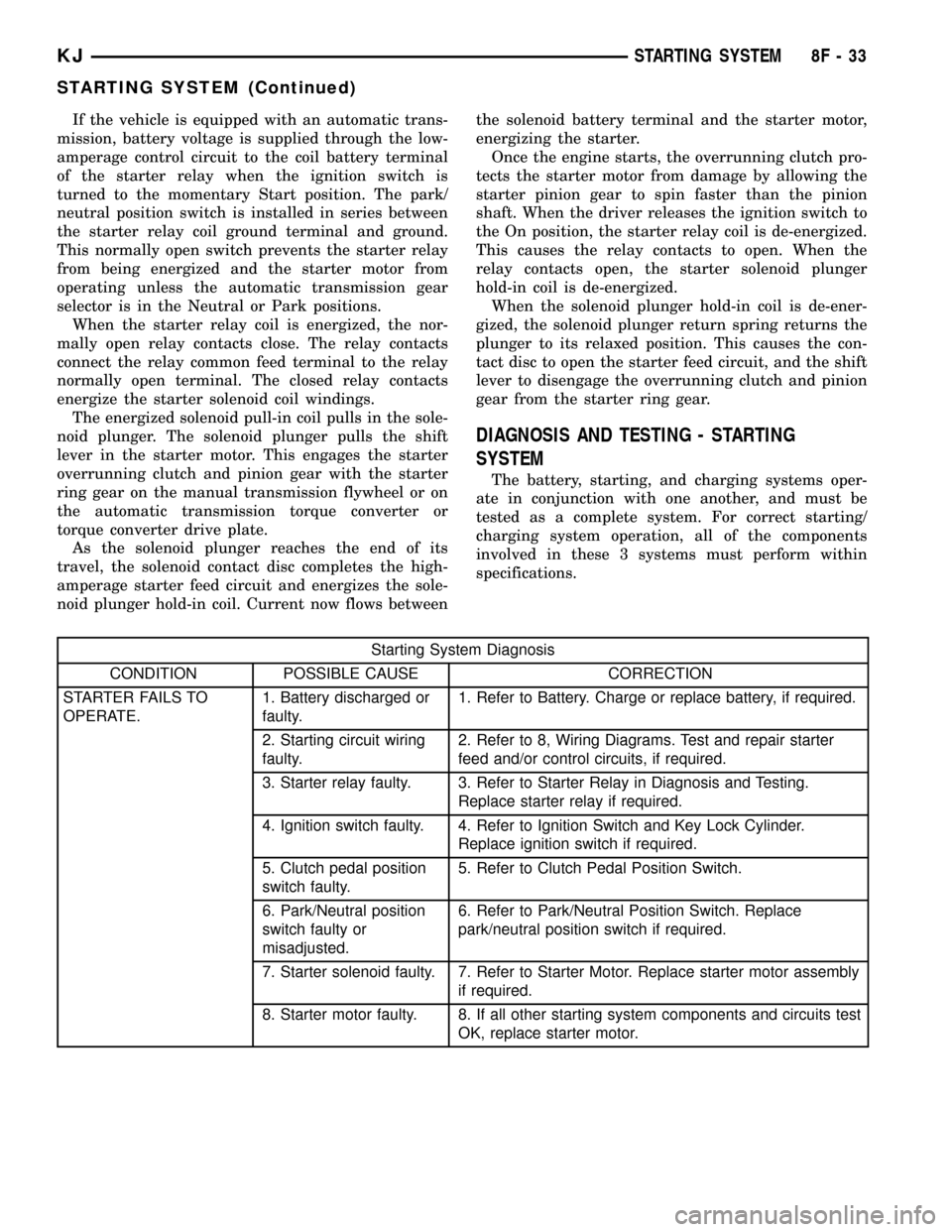
DIAGNOSIS AND TESTING - STARTING
SYSTEM
The battery, starting, and charging systems oper-
ate in conjunction with one another, and must be
tested as a complete system. For correct starting/
charging system operation, all of the components
involved in these 3 systems must perform within
specifications.
Starting System Diagnosis
CONDITION POSSIBLE CAUSE CORRECTION
STARTER FAILS TO
OPERATE.1. Battery discharged or
faulty.1. Refer to Battery. Charge or replace battery, if required.
2. Starting circuit wiring
faulty.2. Refer to 8, Wiring Diagrams. Test and repair starter
feed and/or control circuits, if required.
3. Starter relay faulty. 3. Refer to Starter Relay in Diagnosis and Testing.
Replace starter relay if required.
4. Ignition switch faulty. 4. Refer to Ignition Switch and Key Lock Cylinder.
Replace ignition switch if required.
5. Clutch pedal position
switch faulty.5. Refer to Clutch Pedal Position Switch.
6. Park/Neutral position
switch faulty or
misadjusted.6. Refer to Park/Neutral Position Switch. Replace
park/neutral position switch if required.
7. Starter solenoid faulty. 7. Refer to Starter Motor. Replace starter motor assembly
if required.
8. Starter motor faulty. 8. If all other starting system components and circuits test
OK, replace starter motor.
KJSTARTING SYSTEM 8F - 33
STARTING SYSTEM (Continued)
Page 357 of 1803
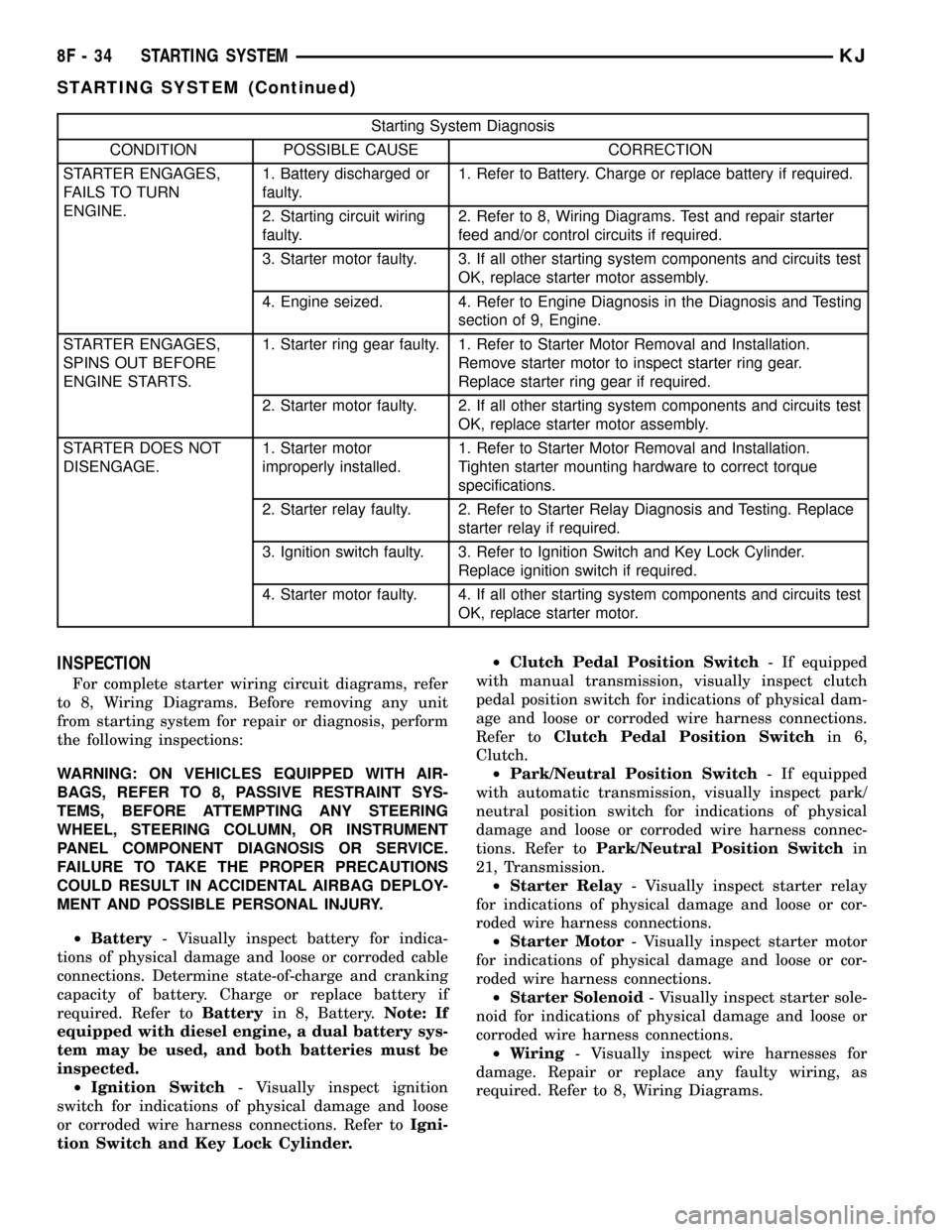
Starting System Diagnosis
CONDITION POSSIBLE CAUSE CORRECTION
STARTER ENGAGES,
FAILS TO TURN
ENGINE.1. Battery discharged or
faulty.1. Refer to Battery. Charge or replace battery if required.
2. Starting circuit wiring
faulty.2. Refer to 8, Wiring Diagrams. Test and repair starter
feed and/or control circuits if required.
3. Starter motor faulty. 3. If all other starting system components and circuits test
OK, replace starter motor assembly.
4. Engine seized. 4. Refer to Engine Diagnosis in the Diagnosis and Testing
section of 9, Engine.
STARTER ENGAGES,
SPINS OUT BEFORE
ENGINE STARTS.1. Starter ring gear faulty. 1. Refer to Starter Motor Removal and Installation.
Remove starter motor to inspect starter ring gear.
Replace starter ring gear if required.
2. Starter motor faulty. 2. If all other starting system components and circuits test
OK, replace starter motor assembly.
STARTER DOES NOT
DISENGAGE.1. Starter motor
improperly installed.1. Refer to Starter Motor Removal and Installation.
Tighten starter mounting hardware to correct torque
specifications.
2. Starter relay faulty. 2. Refer to Starter Relay Diagnosis and Testing. Replace
starter relay if required.
3. Ignition switch faulty. 3. Refer to Ignition Switch and Key Lock Cylinder.
Replace ignition switch if required.
4. Starter motor faulty. 4. If all other starting system components and circuits test
OK, replace starter motor.
INSPECTION
For complete starter wiring circuit diagrams, refer
to 8, Wiring Diagrams. Before removing any unit
from starting system for repair or diagnosis, perform
the following inspections:
WARNING: ON VEHICLES EQUIPPED WITH AIR-
BAGS, REFER TO 8, PASSIVE RESTRAINT SYS-
TEMS, BEFORE ATTEMPTING ANY STEERING
WHEEL, STEERING COLUMN, OR INSTRUMENT
PANEL COMPONENT DIAGNOSIS OR SERVICE.
FAILURE TO TAKE THE PROPER PRECAUTIONS
COULD RESULT IN ACCIDENTAL AIRBAG DEPLOY-
MENT AND POSSIBLE PERSONAL INJURY.
²Battery- Visually inspect battery for indica-
tions of physical damage and loose or corroded cable
connections. Determine state-of-charge and cranking
capacity of battery. Charge or replace battery if
required. Refer toBatteryin 8, Battery.Note: If
equipped with diesel engine, a dual battery sys-
tem may be used, and both batteries must be
inspected.
²Ignition Switch- Visually inspect ignition
switch for indications of physical damage and loose
or corroded wire harness connections. Refer toIgni-
tion Switch and Key Lock Cylinder.²Clutch Pedal Position Switch- If equipped
with manual transmission, visually inspect clutch
pedal position switch for indications of physical dam-
age and loose or corroded wire harness connections.
Refer toClutch Pedal Position Switchin 6,
Clutch.
²Park/Neutral Position Switch- If equipped
with automatic transmission, visually inspect park/
neutral position switch for indications of physical
damage and loose or corroded wire harness connec-
tions. Refer toPark/Neutral Position Switchin
21, Transmission.
²Starter Relay- Visually inspect starter relay
for indications of physical damage and loose or cor-
roded wire harness connections.
²Starter Motor- Visually inspect starter motor
for indications of physical damage and loose or cor-
roded wire harness connections.
²Starter Solenoid- Visually inspect starter sole-
noid for indications of physical damage and loose or
corroded wire harness connections.
²Wiring- Visually inspect wire harnesses for
damage. Repair or replace any faulty wiring, as
required. Refer to 8, Wiring Diagrams.
8F - 34 STARTING SYSTEMKJ
STARTING SYSTEM (Continued)
Page 366 of 1803

REMOVAL
The starter relay is located in the Power Distribu-
tion Center (PDC) (Fig. 14). Refer to label on PDC
cover for relay location.(1) Remove PDC cover.
(2) Remove relay from PDC.
(3) Check condition of relay terminals and PDC
connector terminals for damage or corrosion. Repair
if necessary before installing relay.
(4) Check for pin height (pin height should be the
same for all terminals within the PDC connector).
Repair if necessary before installing relay.
INSTALLATION
(1) Refer to Power Distribution Center (PDC) cover
for starter relay location.
(2) Install relay to PDC.
(3) Install cover to PDC.
Fig. 14 POWER DISTRIBUTION CENTER (PDC)
1 - BATTERY
2 - PDC
3 - PDC COVER
KJSTARTING SYSTEM 8F - 43
STARTER MOTOR RELAY (Continued)