JEEP RENEGADE 2014 1.G Owners Manual
Manufacturer: JEEP, Model Year: 2014, Model line: RENEGADE, Model: JEEP RENEGADE 2014 1.GPages: 212, PDF Size: 17.48 MB
Page 131 of 212
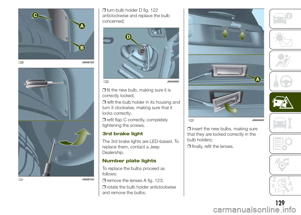
❒turn bulb holder D fig. 122
anticlockwise and replace the bulb
concerned;
❒fit the new bulb, making sure it is
correctly locked;
❒refit the bulb holder in its housing and
turn it clockwise, making sure that it
locks correctly;
❒refit flap C correctly, completely
tightening the screws.
3rd brake light
The 3rd brake lights are LED-based. To
replace them, contact a Jeep
Dealership.
Number plate lights
To replace the bulbs proceed as
follows:
❒remove the lenses A fig. 123;
❒rotate the bulb holder anticlockwise
and remove the bulbs;❒insert the new bulbs, making sure
that they are locked correctly in the
bulb holders;
❒finally, refit the lenses.
120J0A0212C
121J0A0213C
122J0A0302C
123J0A0444C
129
Page 132 of 212
WARNING
133)Before replacing the bulb, wait for the
exhaust ducts to cool down: RISK OF
BURNS!
134)Changes or repairs to the electrical
system carried out incorrectly and without
due consideration for the technical
specifications of the system may lead to
malfunctioning and generate a fire hazard.
135)Halogen bulbs contain pressurised
gas. If they break, glass fragments could fly
everywhere.
WARNING
52)Halogen bulbs must be handled by
holding the metallic part only. Touching the
transparent part of the bulb with your
fingers may reduce the intensity of the
emitted light and even reduce the lifespan
of the bulb. In the case of accidental
contact, rub the lamp with a cloth and
spirit and leave to dry.
REPLACING FUSES
INTRODUCTION
136) 137) 138) 139) 140)
53) 54)
Fuse extracting pliers
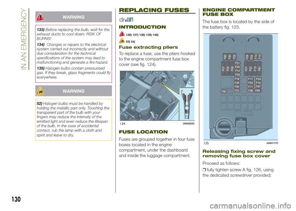
To replace a fuse, use the pliers hooked
to the engine compartment fuse box
cover (see fig. 124).
FUSE LOCATION
Fuses are grouped together in four fuse
boxes located in the engine
compartment, under the dashboard
and inside the luggage compartment.
ENGINE COMPARTMENT
FUSE BOX
The fuse box is located by the side of
the battery fig. 125.
Releasing fixing screw and
removing fuse box cover
Proceed as follows:
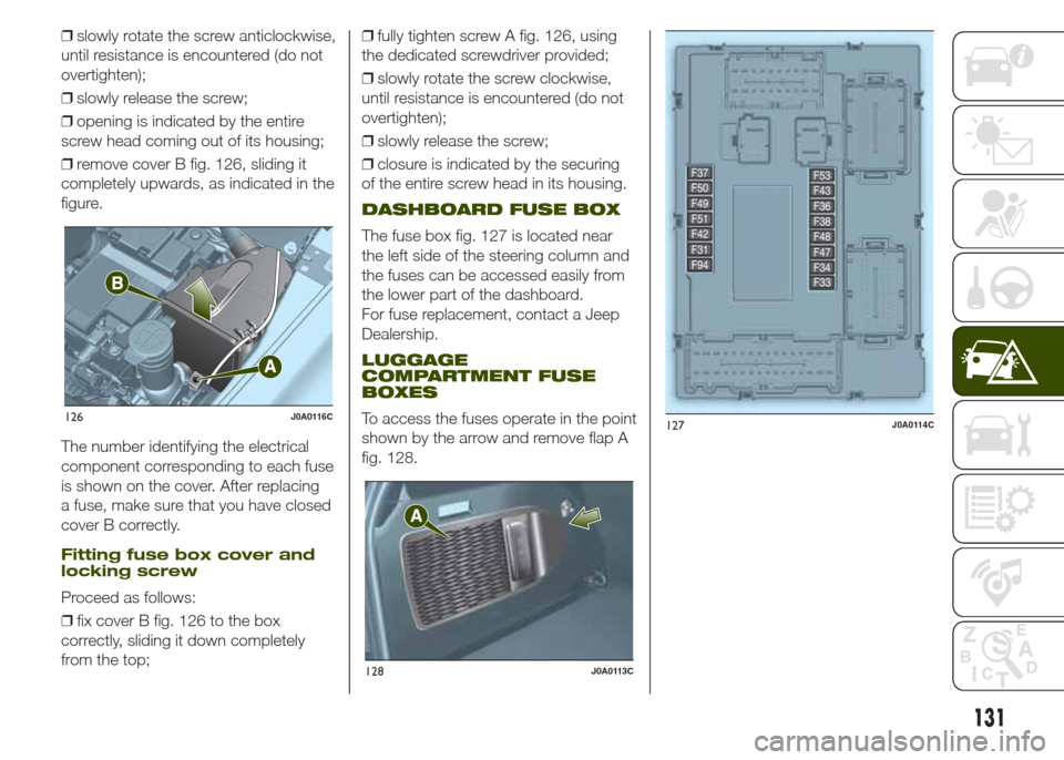
❒fully tighten screw A fig. 126, using
the dedicated screwdriver provided;
124J0A0250C
125J0A0117C
130
IN AN EMERGENCY
Page 133 of 212
❒slowly rotate the screw anticlockwise,
until resistance is encountered (do not
overtighten);
❒slowly release the screw;
❒opening is indicated by the entire
screw head coming out of its housing;
❒remove cover B fig. 126, sliding it
completely upwards, as indicated in the
figure.
The number identifying the electrical
component corresponding to each fuse
is shown on the cover. After replacing
a fuse, make sure that you have closed
cover B correctly.
Fitting fuse box cover and
locking screw
Proceed as follows:
❒fix cover B fig. 126 to the box
correctly, sliding it down completely
from the top;❒fully tighten screw A fig. 126, using
the dedicated screwdriver provided;
❒slowly rotate the screw clockwise,
until resistance is encountered (do not
overtighten);
❒slowly release the screw;
❒closure is indicated by the securing
of the entire screw head in its housing.
DASHBOARD FUSE BOX
The fuse box fig. 127 is located near
the left side of the steering column and
the fuses can be accessed easily from
the lower part of the dashboard.
For fuse replacement, contact a Jeep
Dealership.
LUGGAGE
COMPARTMENT FUSE
BOXES
To access the fuses operate in the point
shown by the arrow and remove flap A
fig. 128.126J0A0116C
128J0A0113C
127J0A0114C
131
Page 134 of 212
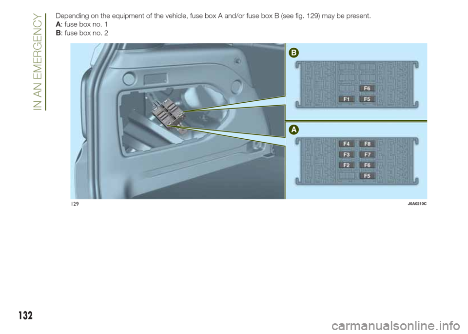
Depending on the equipment of the vehicle, fuse box A and/or fuse box B (see fig. 129) may be present.
A: fuse box no. 1
B: fuse box no. 2
129J0A0210C
132
IN AN EMERGENCY
Page 135 of 212
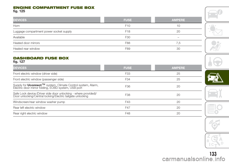
ENGINE COMPARTMENT FUSE BOXfig. 125
DEVICES FUSE AMPERE
HornF10 10
Luggage compartment power socket supply F18 20
AvailableF30 –
Heated door mirrors F88 7,5
Heated rear window F89 30
.
DASHBOARD FUSE BOXfig. 127
DEVICES FUSE AMPERE
Front electric window (driver side) F33 25
Front electric window (passenger side) F34 25
Supply forUconnect
™system, Climate Control system, Alarm,
Electric door mirror folding, EOBD system, USB portF36 20
Safe Lock device (Driver side door unlocking - where provided)/
Door unlocking/Central locking/Electric tailgate unlockingF38 20
Windscreen/rear window washer pump F43 20
Rear left electric window F47 20
Rear right electric window F48 20
133
Page 136 of 212
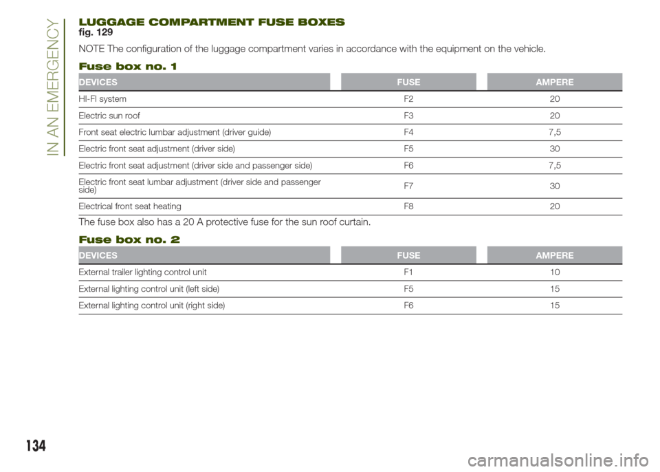
LUGGAGE COMPARTMENT FUSE BOXESfig. 129
NOTE The configuration of the luggage compartment varies in accordance with the equipment on the vehicle.
Fuse box no. 1
DEVICES FUSE AMPERE
HI-FI system F2 20
Electric sun roof F3 20
Front seat electric lumbar adjustment (driver guide) F4 7,5
Electric front seat adjustment (driver side) F5 30
Electric front seat adjustment (driver side and passenger side) F6 7,5
Electric front seat lumbar adjustment (driver side and passenger
side)F7 30
Electrical front seat heating F8 20
The fuse box also has a 20 A protective fuse for the sun roof curtain.
Fuse box no. 2
DEVICES FUSE AMPERE
External trailer lighting control unit F1 10
External lighting control unit (left side) F5 15
External lighting control unit (right side) F6 15
134
IN AN EMERGENCY
Page 137 of 212
WARNING
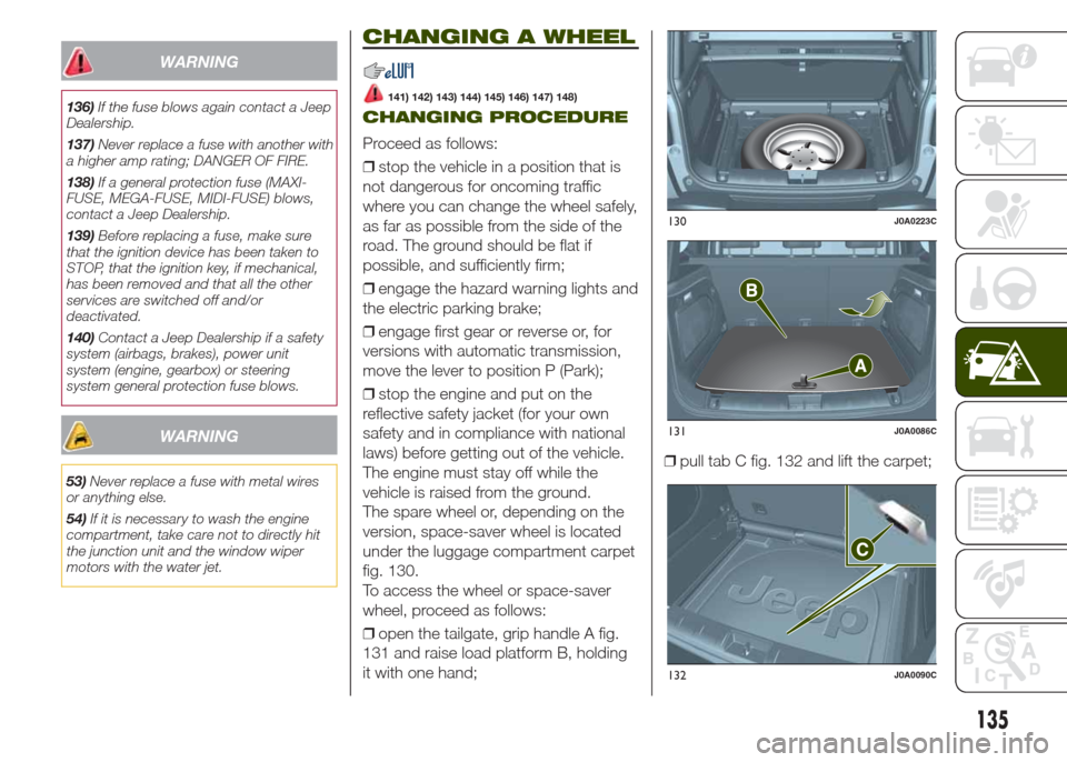
136)If the fuse blows again contact a Jeep
Dealership.
137)Never replace a fuse with another with
a higher amp rating; DANGER OF FIRE.
138)If a general protection fuse (MAXI-
FUSE, MEGA-FUSE, MIDI-FUSE) blows,
contact a Jeep Dealership.
139)Before replacing a fuse, make sure
that the ignition device has been taken to
STOP, that the ignition key, if mechanical,
has been removed and that all the other
services are switched off and/or
deactivated.
140)Contact a Jeep Dealership if a safety
system (airbags, brakes), power unit
system (engine, gearbox) or steering
system general protection fuse blows.
WARNING
53)Never replace a fuse with metal wires
or anything else.
54)If it is necessary to wash the engine
compartment, take care not to directly hit
the junction unit and the window wiper
motors with the water jet.
CHANGING A WHEEL
141) 142) 143) 144) 145) 146) 147) 148)
CHANGING PROCEDURE
Proceed as follows:
❒stop the vehicle in a position that is
not dangerous for oncoming traffic
where you can change the wheel safely,
as far as possible from the side of the
road. The ground should be flat if
possible, and sufficiently firm;
❒engage the hazard warning lights and
the electric parking brake;
❒engage first gear or reverse or, for
versions with automatic transmission,
move the lever to position P (Park);
❒stop the engine and put on the
reflective safety jacket (for your own
safety and in compliance with national
laws) before getting out of the vehicle.
The engine must stay off while the
vehicle is raised from the ground.
The spare wheel or, depending on the
version, space-saver wheel is located
under the luggage compartment carpet
fig. 130.
To access the wheel or space-saver
wheel, proceed as follows:
❒open the tailgate, grip handle A fig.
131 and raise load platform B, holding
it with one hand;❒pull tab C fig. 132 and lift the carpet;
130J0A0223C
131J0A0086C
132J0A0090C
135
Page 138 of 212
❒remove the fixing device for the jack
and the spare wheel;
❒remove the wheel chock;
❒remove the jack unit and the key for
removing the bolts from the spare
wheel. Turn the screw of the jack to
loosen the key and separate it from the
jack assembly;
❒take the spare wheel out of the
luggage compartment.
Tool box (where provided)
On versions with spare wheel there
is also, inside the luggage compartment
(right side), a tool box secured to the
luggage compartment carpet with
dedicated fastenings.
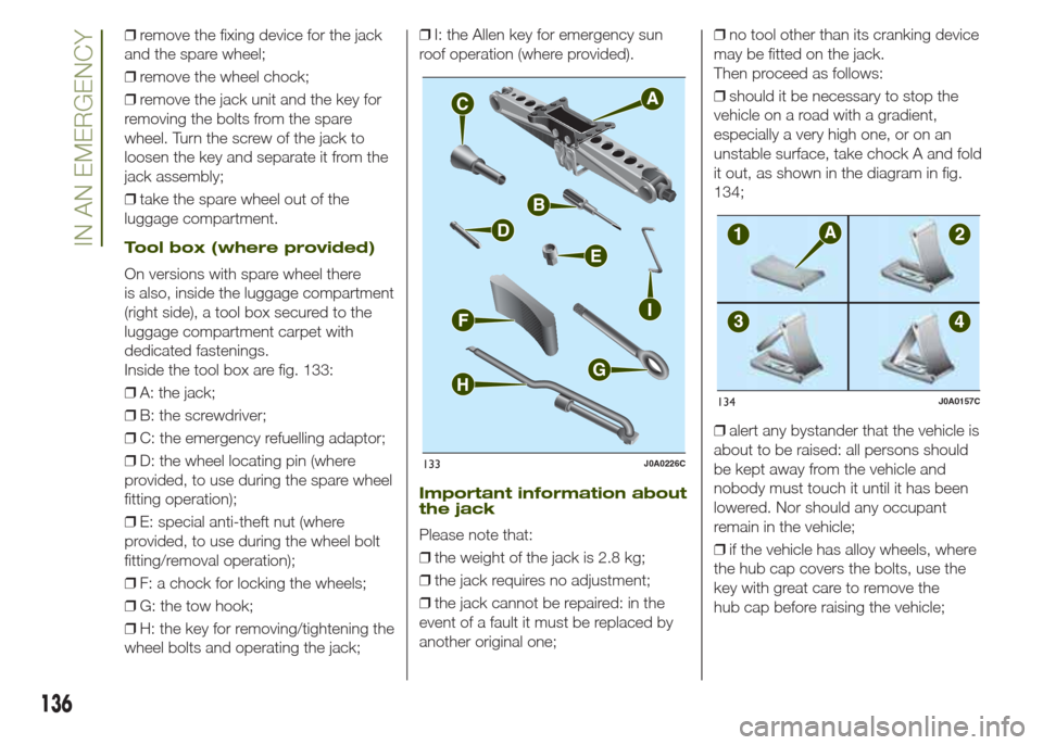
Inside the tool box are fig. 133:
❒A: the jack;
❒B: the screwdriver;
❒C: the emergency refuelling adaptor;
❒D: the wheel locating pin (where
provided, to use during the spare wheel
fitting operation);
❒E: special anti-theft nut (where
provided, to use during the wheel bolt
fitting/removal operation);
❒F: a chock for locking the wheels;
❒G: the tow hook;
❒H: the key for removing/tightening the
wheel bolts and operating the jack;❒I: the Allen key for emergency sun
roof operation (where provided).
Important information about
the jack
Please note that:
❒the weight of the jack is 2.8 kg;
❒the jack requires no adjustment;
❒the jack cannot be repaired: in the
event of a fault it must be replaced by
another original one;❒no tool other than its cranking device
may be fitted on the jack.
Then proceed as follows:
❒should it be necessary to stop the
vehicle on a road with a gradient,
especially a very high one, or on an
unstable surface, take chock A and fold
it out, as shown in the diagram in fig.
134;
❒alert any bystander that the vehicle is
about to be raised: all persons should
be kept away from the vehicle and
nobody must touch it until it has been
lowered. Nor should any occupant
remain in the vehicle;
❒if the vehicle has alloy wheels, where
the hub cap covers the bolts, use the
key with great care to remove the
hub cap before raising the vehicle;
A
C
B
D
E
I
F
G
H
133J0A0226C
134J0A0157C
136
IN AN EMERGENCY
Page 139 of 212
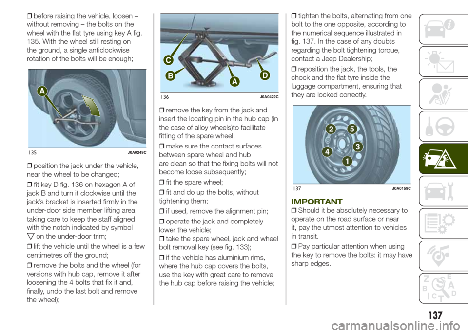
❒before raising the vehicle, loosen –
without removing – the bolts on the
wheel with the flat tyre using key A fig.
135. With the wheel still resting on
the ground, a single anticlockwise
rotation of the bolts will be enough;
❒position the jack under the vehicle,
near the wheel to be changed;
❒fit key D fig. 136 on hexagon A of
jack B and turn it clockwise until the
jack’s bracket is inserted firmly in the
under-door side member lifting area,
taking care to keep the staff aligned
with the notch indicated by symbol
on the under-door trim;
❒lift the vehicle until the wheel is a few
centimetres off the ground;
❒remove the bolts and the wheel (for
versions with hub cap, remove it after
loosening the 4 bolts that fix it and,
finally, undo the last bolt and remove
the wheel);❒remove the key from the jack and
insert the locating pin in the hub cap (in
the case of alloy wheels)to facilitate
fitting of the spare wheel;
❒make sure the contact surfaces
between spare wheel and hub
are clean so that the fixing bolts will not
become loose subsequently;
❒fit the spare wheel;
❒fit and do up the bolts, without
tightening them;
❒if used, remove the alignment pin;
❒operate the jack and completely
lower the vehicle;
❒take the spare wheel, jack and wheel
bolt removal key (see fig. 133);
❒if the vehicle has aluminium rims,
where the hub cap covers the bolts,
use the key with great care to remove
the hub cap before raising the vehicle;❒tighten the bolts, alternating from one
bolt to the one opposite, according to
the numerical sequence illustrated in
fig. 137. In the case of any doubts
regarding the bolt tightening torque,
contact a Jeep Dealership;
❒reposition the jack, the tools, the
chock and the flat tyre inside the
luggage compartment, ensuring that
they are locked correctly.
IMPORTANT
❒Should it be absolutely necessary to
operate on the road surface or near
it, pay the utmost attention to vehicles
in transit.
❒Pay particular attention when using
the key to remove the bolts: it may have
sharp edges.
135J0A0249C
136J0A0422C
137J0A0159C
137
Page 140 of 212
❒Raising the vehicle any more than
necessary may lower its stability: the
jack may slip and injure those nearby.
Do not raise the vehicle any more
than required for the removal of the
wheel.
❒Tyres with unidirectional tread can be
recognised by arrows on the side of
the tyre which indicate the direction of
rotation. This must of necessity be
complied with. Only in this way can the
tyres maintain their characteristics in
terms of grip, noise, resistance to wear
and drainage on wet surfaces.
❒If, after a puncture, it is necessary to
fit such a tyre the wrong way round,
it will be necessary to continue driving
with great care, since the tyre’s
performance is limited in these
conditions. This precaution must be
borne in mind above all when the road
surface is wet.
❒In order to benefit completely from
the unidirectional tread, it is advisable to
restore all wheels to the correct
direction of rotation as soon as
possible.
❒Make sure that the spare wheel is
fitted with the valve facing outwards.
The wheel may be damaged if fitted
incorrectly.❒If the vehicle has a hub cap or wheel
cover, do not attempt to fit it on the
spare wheel.
❒To prevent injury to persons, the
complete tightening of the bolts must
only be carried out when all of the
vehicle’s wheels are on the ground, to
prevent the vehicle falling from the jack.
❒After having travelled for about
40 km, stop and check that the bolts
are tightened correctly.
WARNING
141)If left in the passenger compartment,
the punctured wheel and jack constitute
a serious risk to the safety of occupants in
the event of accidents or sharp braking.
Therefore, always place both the jack and
punctured wheel in the dedicated housing
in the luggage compartment.
142)It is extremely dangerous to attempt
to change a wheel on the side of the
vehicle next to the driving lane: make sure
that the vehicle is at a sufficient distance
from the road, to avoid being run over.
143)Indicate the presence of the stationary
vehicle in accordance with current
regulations: hazard warning lights, warning
triangle, etc. Those on board should get
out of the vehicle, particularly if it is heavily
laden, and wait for the wheel to be
changed away from the threat posed by
the traffic. On slopes or on unsurfaced
roads, chock the wheels with the chocks
provided.144)The vehicle's driving characteristics
will be modified with the space-saver wheel
fitted. Avoid violent acceleration and
braking, abrupt steering and fast cornering.
The overall duration of the space-saver
wheel is of about 3000 km, after which the
relevant tyre must be replaced with another
one of the same type. Never install a
standard tyre on a rim that is designed for
use with a space-saver wheel. Have the
wheel repaired and refitted as soon as
possible. Using two or more space-saver
wheels at the same time is forbidden.
Do not grease the threads of the bolts
before fitting them: they might slip out
when driving!
145)The space-saver wheel (where
provided) is specific to your vehicle: do not
use it on other models, or use the
space-saver wheel of other models on your
vehicle. The space-saver wheel must only
be used in the event of emergency. It
must only be used for the distance
necessary to reach a service point and the
vehicle speed must not exceed 80 km/h.
The space-saver wheel has an orange label
that summarises the main cautions for
use and limitations. Never remove or cover
the label. Never apply a hub cap on a
space-saver wheel.
138
IN AN EMERGENCY