JEEP RENEGADE 2014 1.G Owners Manual
Manufacturer: JEEP, Model Year: 2014, Model line: RENEGADE, Model: JEEP RENEGADE 2014 1.GPages: 212, PDF Size: 17.48 MB
Page 121 of 212
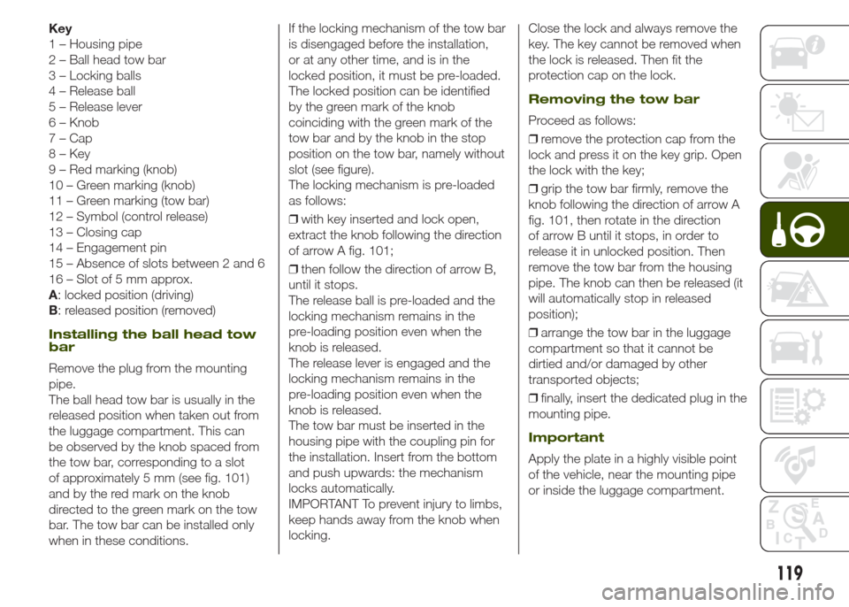
Key
1 – Housing pipe
2 – Ball head tow bar
3 – Locking balls
4 – Release ball
5 – Release lever
6 – Knob
7 – Cap
8 – Key
9 – Red marking (knob)
10 – Green marking (knob)
11 – Green marking (tow bar)
12 – Symbol (control release)
13 – Closing cap
14 – Engagement pin
15 – Absence of slots between 2 and 6
16 – Slot of 5 mm approx.
A: locked position (driving)
B: released position (removed)
Installing the ball head tow
bar
Remove the plug from the mounting
pipe.
The ball head tow bar is usually in the
released position when taken out from
the luggage compartment. This can
be observed by the knob spaced from
the tow bar, corresponding to a slot
of approximately 5 mm (see fig. 101)
and by the red mark on the knob
directed to the green mark on the tow
bar. The tow bar can be installed only
when in these conditions.If the locking mechanism of the tow bar
is disengaged before the installation,
or at any other time, and is in the
locked position, it must be pre-loaded.
The locked position can be identified
by the green mark of the knob
coinciding with the green mark of the
tow bar and by the knob in the stop
position on the tow bar, namely without
slot (see figure).
The locking mechanism is pre-loaded
as follows:
❒with key inserted and lock open,
extract the knob following the direction
of arrow A fig. 101;
❒then follow the direction of arrow B,
until it stops.
The release ball is pre-loaded and the
locking mechanism remains in the
pre-loading position even when the
knob is released.
The release lever is engaged and the
locking mechanism remains in the
pre-loading position even when the
knob is released.
The tow bar must be inserted in the
housing pipe with the coupling pin for
the installation. Insert from the bottom
and push upwards: the mechanism
locks automatically.
IMPORTANT To prevent injury to limbs,
keep hands away from the knob when
locking.Close the lock and always remove the
key. The key cannot be removed when
the lock is released. Then fit the
protection cap on the lock.
Removing the tow bar
Proceed as follows:
❒remove the protection cap from the
lock and press it on the key grip. Open
the lock with the key;
❒grip the tow bar firmly, remove the
knob following the direction of arrow A
fig. 101, then rotate in the direction
of arrow B until it stops, in order to
release it in unlocked position. Then
remove the tow bar from the housing
pipe. The knob can then be released (it
will automatically stop in released
position);
❒arrange the tow bar in the luggage
compartment so that it cannot be
dirtied and/or damaged by other
transported objects;
❒finally, insert the dedicated plug in the
mounting pipe.
Important
Apply the plate in a highly visible point
of the vehicle, near the mounting pipe
or inside the luggage compartment.
119
Page 122 of 212
To ensure correct operation of the
system, periodically remove all deposits
of dirt which may have accumulated
on the ball head bar and from the
mounting pipe. The lock must only be
treated with graphite.
Periodically lubricate the joints, the
sliding surfaces and the balls with
grease without resin or oil. Lubrication
is also a further corrosion protection.
if the vehicle is washed with high-
pressure jets, the ball head bar must be
removed and the dedicated plug fitted.
The ball head bar must never be
treated with high-pressure jets.
Two keys are supplied together with the
removable ball tow bar. Note down
the four-digit key number and keep it in
a safe place. This number is to be
used for ordering any duplicate keys
that may be required.
IMPORTANT To install a tow hook
contact a Jeep Dealership.
WARNING
128)The ABS with which the vehicle is
equipped will not control the braking
system of the trailer. Particular caution is
therefore required on slippery surfaces.
129)Never modify the braking system of
the vehicle to control the trailer brake. The
trailer braking system must be fully
independent of the vehicle’s hydraulic
system.
REFUELLING THE
VEHICLE
Always stop the engine before
refuelling.
130) 131) 132)
PETROL ENGINES
Only use unleaded petrol with a number
of octanes (R.O.N.) not lower than 95
(EN228 specification).
DIESEL ENGINES
51)Only use Diesel for motor vehicles
(EN590 specification).
When using or parking the vehicle for a
long time in the mountains or cold
areas, it is advisable to refuel using
locally available diesel. In this case, it is
also advisable to keep the tank over
50% full.
REFUELLING
PROCEDURE
The fuel flap is unlocked when the
central door locking system is released,
while it is automatically locked when
the central locking system is applied.
Opening the flap
To refuel proceed as follows:
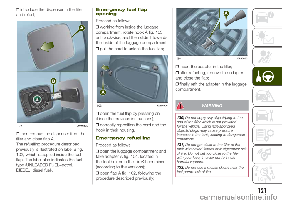
❒open flap A fig. 102, from the point
shown by the arrow;
120
STARTING AND DRIVING
Page 123 of 212
❒introduce the dispenser in the filler
and refuel;
❒then remove the dispenser from the
filler and close flap A.
The refuelling procedure described
previously is illustrated on label B fig.
102, which is applied inside the fuel
flap. The label also indicates the fuel
type (UNLEADED FUEL=petrol,
DIESEL=diesel fuel).Emergency fuel flap
opening
Proceed as follows:
❒working from inside the luggage
compartment, rotate hook A fig. 103
anticlockwise, and then slide it towards
the inside of the luggage compartment:
❒pull the cord to unlock the fuel flap;
❒open the fuel flap by pressing on
it (see the previous instructions);
❒correctly reposition the cord and the
hook in their housing.
Emergency refuelling
Proceed as follows:
❒open the luggage compartment and
take adapter A fig. 104, located in
the tool box or in the TireKit container
(according to the versions);
❒open flap A fig. 102, following the
procedure described previously;❒insert the adapter in the filler;
❒after refuelling, remove the adapter
and close the flap;
❒finally refit the adapter in the luggage
compartment.
WARNING
130)Do not apply any object/plug to the
end of the filler which is not provided
for the vehicle. Using non-approved
objects/plugs may cause pressure
increase in the tank, leading to dangerous
conditions.
131)Do not get close to the filler of the
tank with naked flames or lit cigarettes: risk
of fire. Do not get too close to the filler
with your face, in order not to inhale
harmful vapours.
132)Do not use a mobile phone near the
fuel pump: risk of fire.
102J0A0182C
103J0A0400C
104J0A0200C
121
Page 124 of 212
WARNING
51)The vehicle must only be filled with
diesel fuel for motor vehicles, in
compliance with European Standard EN
590. The use of other products or mixtures
may damage the engine beyond repair
and consequently invalidate the warranty,
due to the damage caused. If you
accidentally refuel with another type of fuel,
do not start the engine, and drain the
tank. If the engine has run, even for a very
short time, you will need to have the entire
fuel supply system emptied in addition to
the tank.
122
STARTING AND DRIVING
Page 125 of 212
IN AN EMERGENCY
A punctured tyre or a burnt-out bulb?
At times, a problem may interfere
with our journey.
The pages on emergencies can help
you to deal with critical situations
independently and with calm.
In an emergency we recommend that
you call the freephone number found in
the Warranty Booklet.
It is also possible to call the national or
international universal freephone
number to search for the nearest
Dealership.HAZARD WARNING LIGHTS...........124
REPLACING A BULB ......................124
REPLACING FUSES........................130
CHANGING A WHEEL ...................135
TIREKIT ...........................................139
JUMP STARTING ............................141
FUEL CUT-OFF SYSTEM ................143
AUTOMATIC TRANSMISSION
GEAR LEVER UNLOCKING.............143
TOWING THE VEHICLE ..................145
BROKEN-DOWN VEHICLE
TOWING .........................................146
123
Page 126 of 212
HAZARD WARNING
LIGHTS
CONTROL
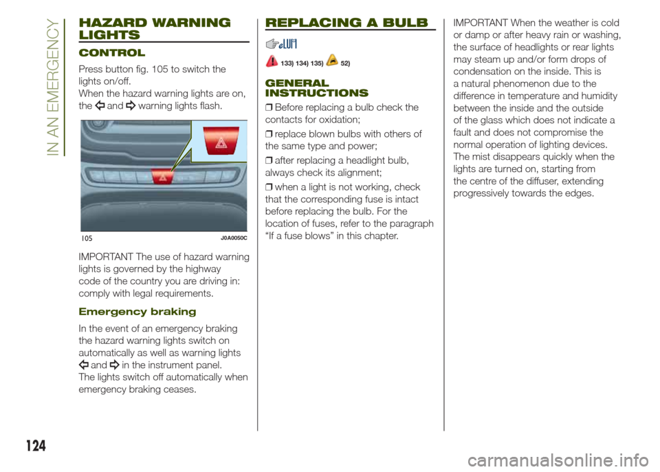
Press button fig. 105 to switch the
lights on/off.
When the hazard warning lights are on,
the
andwarning lights flash.
IMPORTANT The use of hazard warning
lights is governed by the highway
code of the country you are driving in:
comply with legal requirements.
Emergency braking
In the event of an emergency braking
the hazard warning lights switch on
automatically as well as warning lights
andin the instrument panel.
The lights switch off automatically when
emergency braking ceases.
REPLACING A BULB
133) 134) 135)52)
GENERAL
INSTRUCTIONS
❒Before replacing a bulb check the
contacts for oxidation;
❒replace blown bulbs with others of
the same type and power;
❒after replacing a headlight bulb,
always check its alignment;
❒when a light is not working, check
that the corresponding fuse is intact
before replacing the bulb. For the
location of fuses, refer to the paragraph
“If a fuse blows” in this chapter.IMPORTANT When the weather is cold
or damp or after heavy rain or washing,
the surface of headlights or rear lights
may steam up and/or form drops of
condensation on the inside. This is
a natural phenomenon due to the
difference in temperature and humidity
between the inside and the outside
of the glass which does not indicate a
fault and does not compromise the
normal operation of lighting devices.
The mist disappears quickly when the
lights are turned on, starting from
the centre of the diffuser, extending
progressively towards the edges.
105J0A0050C
124
IN AN EMERGENCY
Page 127 of 212
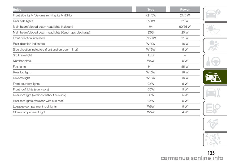
BulbsType Power
Front side lights/Daytime running lights (DRL) P21/5W 21/5 W
Rear side lightsP21W 21 W
Main beam/dipped beam headlights (halogen) H4 60/55 W
Main beam/dipped beam headlights (Xenon gas discharge) D5S 25 W
Front direction indicatorsPY21W 21 W
Rear direction indicatorsW16W 16 W
Side direction indicators (front and on door mirror) WY5W 5 W
3rd brake lightLED –
Number plateW5W 5 W
Fog lightsH11 55 W
Rear fog lightW16W 16 W
Reverse lightW16W 16 W
Front courtesy lightsC5W 5 W
Front roof lights (sun visors)C5W 5 W
Rear roof light (versions without sun roof) C5W 5 W
Rear roof lights (versions with sun roof) C5W 5 W
Luggage compartment roof lights W5W 5 W
Glove compartment lightW5W 4 W
125
Page 128 of 212
CHANGING AN EXTERIOR
LIGHT
Front upper light cluster
(main beam/dipped halogen
headlights)
To replace the bulb, proceed as follows:
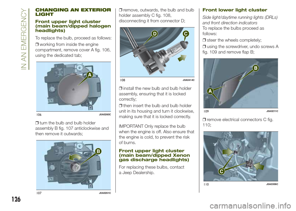
❒working from inside the engine
compartment, remove cover A fig. 106,
using the dedicated tab;
❒turn the bulb and bulb holder
assembly B fig. 107 anticlockwise and
then remove it outwards;❒remove, outwards, the bulb and bulb
holder assembly C fig. 108,
disconnecting it from connector D;
❒install the new bulb and bulb holder
assembly, ensuring that it is locked
correctly;
❒then insert the bulb and bulb holder
unit in its housing and turn it clockwise,
making sure that it is locked correctly.
IMPORTANT Only replace the bulb
when the engine is off. Also ensure that
the engine is cold, to prevent the risk
of burns.
Front upper light cluster
(main beam/dipped Xenon
gas discharge headlights)
For replacing these bulbs, contact
a Jeep Dealership.
Front lower light cluster
Side light/daytime running lights (DRLs)
and front direction indicators
To replace the bulbs proceed as
follows:
❒steer the wheels completely;
❒using the screwdriver, undo screws A
fig. 109 and remove flap B;
❒remove electrical connectors C fig.
110;
106J0A0260C
107J0A0261C
108J0A0414C
109J0A0211C
110J0A0306C
126
IN AN EMERGENCY
Page 129 of 212
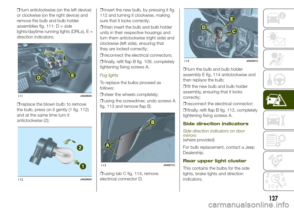
❒turn anticlockwise (on the left device)
or clockwise (on the right device) and
remove the bulb and bulb holder
assemblies fig. 111: D = side
lights/daytime running lights (DRLs), E =
direction indicators;
❒replace the blown bulb: to remove
the bulb, press on it gently (1 fig. 112)
and at the same time turn it
anticlockwise (2);❒insert the new bulb, by pressing it fig.
112 and turning it clockwise, making
sure that it locks correctly;
❒then insert the bulb and bulb holder
units in their respective housings and
turn them anticlockwise (right side) and
clockwise (left side), ensuring that
they are locked correctly;
❒reconnect the electrical connectors;
❒finally, refit flap B fig. 109, completely
tightening fixing screws A.
Fog lights
To replace the bulbs proceed as
follows:
❒steer the wheels completely;
❒using the screwdriver, undo screws A
fig. 113 and remove flap B;
❒using tab C fig. 114, remove
electrical connector D;❒turn the bulb and bulb holder
assembly E fig. 114 anticlockwise and
then replace the bulb;
❒fit the new bulb and bulb holder
assembly, ensuring that it locks
correctly;
❒reconnect the electrical connector;
❒finally, refit flap B fig. 113, completely
tightening fixing screws A.
Side direction indicators
Side direction indicators on door
mirrors
(where provided)
For bulb replacement, contact a Jeep
Dealership.
Rear upper light cluster
This contains the bulbs for the side
lights, brake lights and direction
indicators.
111J0A0263C
112J0A0264C
113J0A0211C
114J0A0301C
127
Page 130 of 212
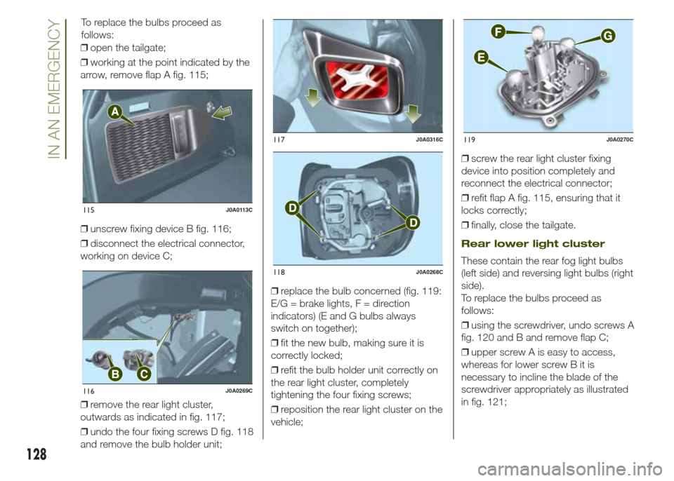
❒open the tailgate;
❒working at the point indicated by the
arrow, remove flap A fig. 115;
❒unscrew fixing device B fig. 116;
❒disconnect the electrical connector,
working on device C;
❒remove the rear light cluster,
outwards as indicated in fig. 117;
❒undo the four fixing screws D fig. 118
and remove the bulb holder unit;❒replace the bulb concerned (fig. 119:
E/G = brake lights, F = direction
indicators) (E and G bulbs always
switch on together);
❒fit the new bulb, making sure it is
correctly locked;
❒refit the bulb holder unit correctly on
the rear light cluster, completely
tightening the four fixing screws;
❒reposition the rear light cluster on the
vehicle;❒screw the rear light cluster fixing
device into position completely and
reconnect the electrical connector;
❒refit flap A fig. 115, ensuring that it
locks correctly;
❒finally, close the tailgate.
Rear lower light cluster
These contain the rear fog light bulbs
(left side) and reversing light bulbs (right
side).
To replace the bulbs proceed as
follows:
❒using the screwdriver, undo screws A
fig. 120 and B and remove flap C;
❒upper screw A is easy to access,
whereas for lower screw B it is
necessary to incline the blade of the
screwdriver appropriately as illustrated
in fig. 121;
115J0A0113C
116J0A0269C
117J0A0316C
118J0A0268C
119J0A0270C
128
IN AN EMERGENCY
To replace the bulbs proceed as
follows: