tow JEEP RENEGADE 2018 Owner handbook (in English)
[x] Cancel search | Manufacturer: JEEP, Model Year: 2018, Model line: RENEGADE, Model: JEEP RENEGADE 2018Pages: 356, PDF Size: 6.11 MB
Page 170 of 356
PARKSENSE SYSTEM
(where provided)
VERSIONS WITH 4 SENSORS
140)61) 62)
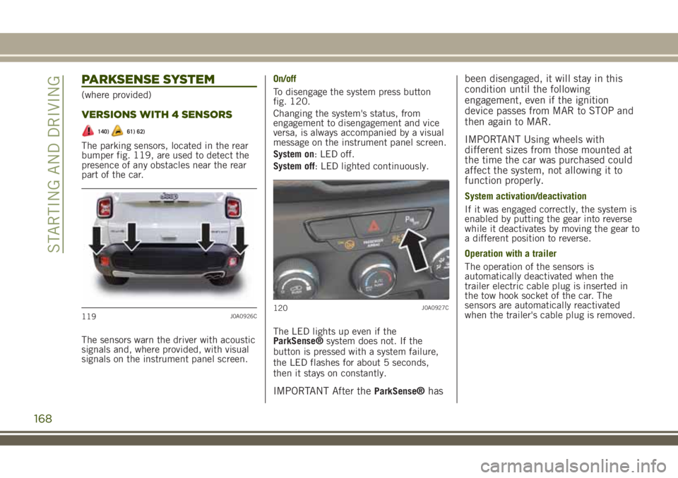
The parking sensors, located in the rear
bumper fig. 119, are used to detect the
presence of any obstacles near the rear
part of the car.
The sensors warn the driver with acoustic
signals and, where provided, with visual
signals on the instrument panel screen.On/off
To disengage the system press button
fig. 120.
Changing the system's status, from
engagement to disengagement and vice
versa, is always accompanied by a visual
message on the instrument panel screen.
System on: LED off.
System off: LED lighted continuously.
The LED lights up even if the
ParkSense®system does not. If the
button is pressed with a system failure,
the LED flashes for about 5 seconds,
then it stays on constantly.
IMPORTANT After theParkSense®hasbeen disengaged, it will stay in this
condition until the following
engagement, even if the ignition
device passes from MAR to STOP and
then again to MAR.
IMPORTANT Using wheels with
different sizes from those mounted at
the time the car was purchased could
affect the system, not allowing it to
function properly.
System activation/deactivation
If it was engaged correctly, the system is
enabled by putting the gear into reverse
while it deactivates by moving the gear to
a different position to reverse.
Operation with a trailer
The operation of the sensors is
automatically deactivated when the
trailer electric cable plug is inserted in
the tow hook socket of the car. The
sensors are automatically reactivated
when the trailer's cable plug is removed.
119J0A0926C120J0A0927C
168
STARTING AND DRIVING
Page 171 of 356
VERSIONS WITH 12 SENSORS
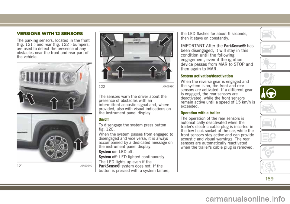
The parking sensors, located in the front
(fig. 121 ) and rear (fig. 122 ) bumpers,
are used to detect the presence of any
obstacles near the front and rear part of
the vehicle.
The sensors warn the driver about the
presence of obstacles with an
intermittent acoustic signal and, where
provided, also with visual indications on
the instrument panel display.
On/off
To disengage the system press button
fig. 120.
When the system passes from engaged to
disengaged and vice versa, it is always
accompanied by a dedicated message on
the instrument panel display.
System on: LED off.
System off: LED lighted continuously.
The LED lights up even if the
ParkSense®system does not. If the
button is pressed with a system failure,the LED flashes for about 5 seconds,
then it stays on constantly.
IMPORTANT After theParkSense®has
been disengaged, it will stay in this
condition until the following
engagement, even if the ignition
device passes from MAR to STOP and
then again to MAR.
System activation/deactivation
When the reverse gear is engaged and
the system is on, the front and rear
sensors are activated. If a different gear
is engaged, the rear sensors are
deactivated, while the front sensors
remain active until a speed of 15 km/h is
exceeded.
Operation with a trailer
The operation of the rear sensors is
automatically deactivated when the
trailer's electric cable plug is inserted in
the tow hook socket of the car, while the
front sensors stay active and can provide
acoustic and visual warnings. The rear
sensors are automatically reactivated
when the trailer's cable plug is removed.
121J0A0164C
122J0A0699C
169
Page 172 of 356
GENERAL WARNINGS
Some conditions may influence the
performance of the parking system:
reduced sensor sensitivity and a
reduction in the parking assistance
system performance could be due to the
presence of: ice, snow, mud, thick paint,
on the surface of the sensor;
the sensor may detect a non-existent
obstacle ("echo interference") due to
mechanical interference, for example
when washing the vehicle, in rain (strong
wind), hail;
the signals sent by the sensor can
also be altered by the presence of
ultrasonic systems (e.g. pneumatic brake
systems of trucks or pneumatic drills)
near the vehicle;
Parking assistance system
performance can also be influenced by
the position of the sensors, for example
due to a change in the ride setting
(caused by wear to the shock absorbers,
suspension), or by changing tyres,
overloading the vehicle or carrying out
specific tuning operations that require
the vehicle to be lowered.
the presence of a tow hook without
trailer, which may interfere with the
correct operation of the parking sensors.
Before using theParkSense®system, it
is recommended to remove the
removable tow hook ball assembly andthe relevant attachment from the vehicle
when the latter is not used for towing
operations. Failure to comply with this
prescription may cause personal injuries
or damage to vehicles or obstacles since,
when the continuous acoustic signal is
emitted, the tow hook ball is already in a
position that is much closer to the
obstacle than the rear bumper. If you
wish to leave the tow hook fitted without
towing a trailer, it is advisable to contact
a Jeep Dealership for the relevant system
update operations because the tow hook
could be detected as an obstacle
ParkSense®by the central sensors.
the presence of adhesives on the
sensors. Thus take care not to place
adhesives on the sensors.
WARNING
140)Parking and other potentially
dangerous manoeuvres are, however,
always the driver’s responsibility. When
performing these operations, always make
sure that there are no other people
(especially children) or animals on the
route you want to take. The parking
sensors are an aid for the driver, but the
driver must never allow their attention to
lapse during potentially dangerous
manoeuvres, even those executed at low
speeds.
170
STARTING AND DRIVING
Page 179 of 356
OPERATION WITH A TRAILER
The system is automatically deactivated
when the trailer's electric plug is inserted
in the vehicle's tow hook socket. The rear
sensors are automatically reactivated
when the trailer's cable plug is removed.
IMPORTANT INFORMATION
Some conditions may influence the
performance of the Side Distance
Warning system:
reduced sensor sensitivity and a
reduction in the parking assistance
system performance could be due to the
presence of: ice, snow, mud, thick paint,
on the surface of the sensor;
the sensor may detect a non-existent
obstacle ("echo interference") due to
mechanical interference, for example
when washing the vehicle, in rain (strong
wind), hail;
the signals sent by the sensor can
also be altered by the presence of
ultrasonic systems (e.g. pneumatic brake
systems of trucks or pneumatic drills)
near the vehicle;
Parking assistance system
performance can also be influenced by
the position of the sensors, for example
due to a change in the ride setting
(caused by wear to the shock absorbers,
suspension), or by changing tyres,
overloading the vehicle or carrying outspecific tuning operations that require
the vehicle to be lowered.
the presence of a tow hook without
trailer, which may interfere with the
correct operation of the parking sensors.
Before using the ParkSense system, it is
recommended to remove the removable
tow hook ball assembly and the relevant
attachment from the vehicle when the
latter is not used for towing operations.
Failure to comply with this prescription
may cause personal injuries or damage to
vehicles or obstacles since, when the
continuous acoustic signal is emitted,
the tow hook ball is already in a position
that is much closer to the obstacle than
the rear bumper. If you wish to leave the
tow hook fitted without towing a trailer, it
is advisable to contact a Jeep Dealership
for the ParkSense system update
operations because the tow hook could
be detected as an obstacle by the central
sensors.
The presence of stickers on the
sensors can adversely affect the correct
operation of the system. Therefore, take
care not to place adhesives on the
sensors.
IMPORTANT
66)The sensors must be clean of mud,
dirt, snow or ice in order for the system to
operate correctly. While cleaning the
sensors, make sure not to scratch or
damage them; avoid using dry, rough or
hard cloths. The sensors should be washed
using clean water with the addition of car
shampoo if necessary. When using special
washing equipment such as high pressure
jets or steam cleaning, clean the sensors
very quickly keeping the jet more than
10 cm away.
67)Only have the bumpers repainted or
any retouches to the paintwork in the area
of the sensors carried out by a Jeep
Dealership. Incorrect paint application
could affect the operation of the parking
sensors.
177
Page 182 of 356
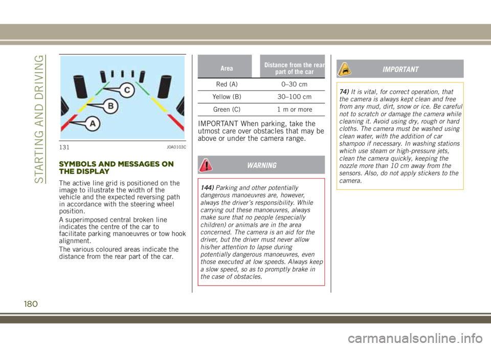
SYMBOLS AND MESSAGES ON
THE DISPLAY
The active line grid is positioned on the
image to illustrate the width of the
vehicle and the expected reversing path
in accordance with the steering wheel
position.
A superimposed central broken line
indicates the centre of the car to
facilitate parking manoeuvres or tow hook
alignment.
The various coloured areas indicate the
distance from the rear part of the car.
AreaDistance from the rear
part of the car
Red (A) 0–30 cm
Yellow (B) 30–100 cm
Green (C) 1 m or more
IMPORTANT When parking, take the
utmost care over obstacles that may be
above or under the camera range.
WARNING
144)Parking and other potentially
dangerous manoeuvres are, however,
always the driver’s responsibility. While
carrying out these manoeuvres, always
make sure that no people (especially
children) or animals are in the area
concerned. The camera is an aid for the
driver, but the driver must never allow
his/her attention to lapse during
potentially dangerous manoeuvres, even
those executed at low speeds. Always keep
a slow speed, so as to promptly brake in
the case of obstacles.
IMPORTANT
74)It is vital, for correct operation, that
the camera is always kept clean and free
from any mud, dirt, snow or ice. Be careful
not to scratch or damage the camera while
cleaning it. Avoid using dry, rough or hard
cloths. The camera must be washed using
clean water, with the addition of car
shampoo if necessary. In washing stations
which use steam or high-pressure jets,
clean the camera quickly, keeping the
nozzle more than 10 cm away from the
sensors. Also, do not apply stickers to the
camera.
131J0A0103C
180
STARTING AND DRIVING
Page 184 of 356
in which the vehicle is sold. If you are
in a different country, find out what
type of adaptor is used there.
IMPORTANT Before refuelling with
LPG, the qualified personnel must
make sure that the adapter is correctly
screwed onto the filler.
IMPORTANT Look after the LPG
adapter carefully so that it does not get
damaged.
IMPORTANT Only use LPG for motor
vehicles.
IMPORTANT Only use the adapter
supplied with the vehicle as it is
equipped with a dedicated fuel
pre-filter.
REFUELLING PROCEDURE
Opening the flap
To refuel proceed as follows:
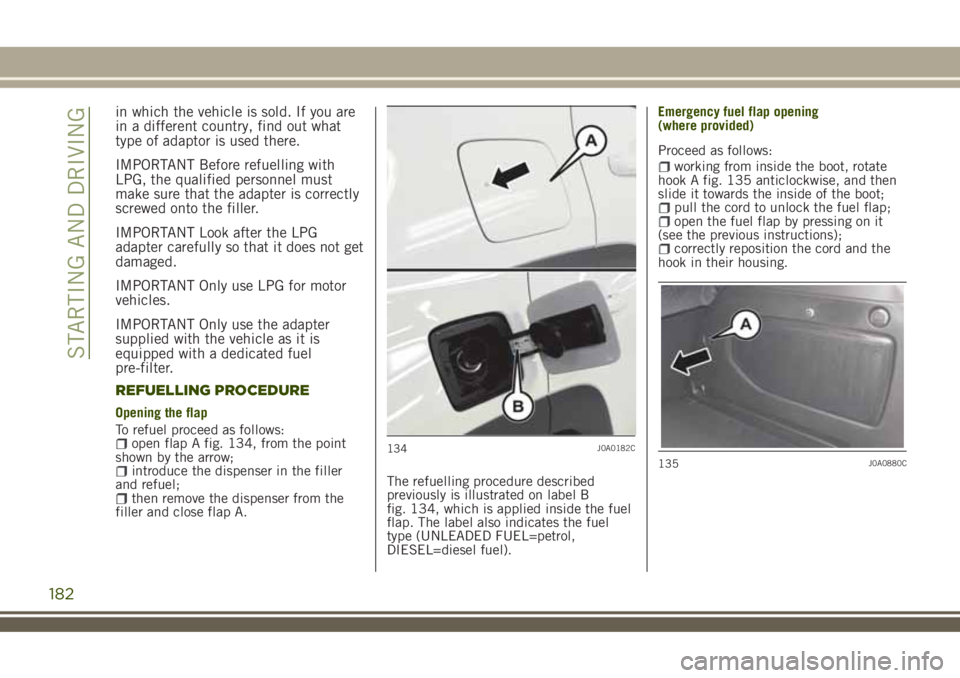
open flap A fig. 134, from the point
shown by the arrow;
introduce the dispenser in the filler
and refuel;
then remove the dispenser from the
filler and close flap A.The refuelling procedure described
previously is illustrated on label B
fig. 134, which is applied inside the fuel
flap. The label also indicates the fuel
type (UNLEADED FUEL=petrol,
DIESEL=diesel fuel).Emergency fuel flap opening
Proceed as follows:
working from inside the boot, rotate
hook A fig. 135 anticlockwise, and then
slide it towards the inside of the boot;
pull the cord to unlock the fuel flap;open the fuel flap by pressing on it
(see the previous instructions);
correctly reposition the cord and the
hook in their housing.
134J0A0182C
135J0A0880C
182
STARTING AND DRIVING
(where provided)
Page 187 of 356
TOWING TRAILERS
TOW HOOK SETUP
148) 149)
Instructions for using the removable ball
head tow bar
IMPORTANT Before setting off,checkthe
correctlockingof the removable ball
head tow bar, as follows:
the green mark of the knob must
coincide with the green mark on the tow
bar;
the knob is in the stop position on the
tow bar (without slot);
locked lock and key removed. The
knob cannot be removed;
ball head bar firmly secured to the
housing pipe. Check by shaking with a
hand.
The fitting procedure must be repeated if
any of the requirements are not met.
If even only one of the requirements is
not met the tow hookmust notbe used,
since there is risk of causing accidents.
Contact a Jeep Dealership.
The ball head tow bar can be
fitted/removed manually, without
requiring specific equipment.
IMPORTANT Never use vehicles or
work tools: the mechanism may be
damaged.
IMPORTANT Never unlock in the case
of trailer attached to the vehicle or
with rack fitted.
IMPORTANT When driving without
trailer (or without rack), the ball head
tow bar must be removed and the
closing plug must always be inserted
in the housing pipe. This applies
particularly if, due to the bar, the
visibility of the number plate or of the
lighting system is reduced.
185
Page 188 of 356
REMOVABLE BALL HEAD TOW BAR
137J0A0423C
186
STARTING AND DRIVING
Page 189 of 356
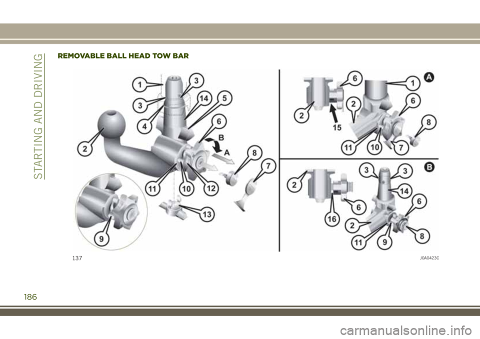
Key
1 – Housing pipe
2 – Ball head tow bar
3 – Locking balls
4 – Release ball
5 – Release lever
6 – Knob
7 – Cap
8 – Key
9 – Red marking (knob)
10 – Green marking (knob)
11 – Green marking (tow bar)
12 – Symbol (control release)
13 – Closing cap
14 – Engagement pin
15 – Absence of slots between 2 and 6
16 – Slot of 5 mm approx.
A: locked position (driving)
B: released position (removed)
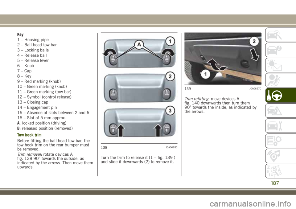
Tow hook trim
Before fitting the ball head tow bar, the
tow hook trim on the rear bumper must
be removed.
Trim removal: rotate devices A
fig. 138 90° towards the outside, as
indicated by the arrows. Then move them
upwards.Turn the trim to release it (1 – fig. 139 )
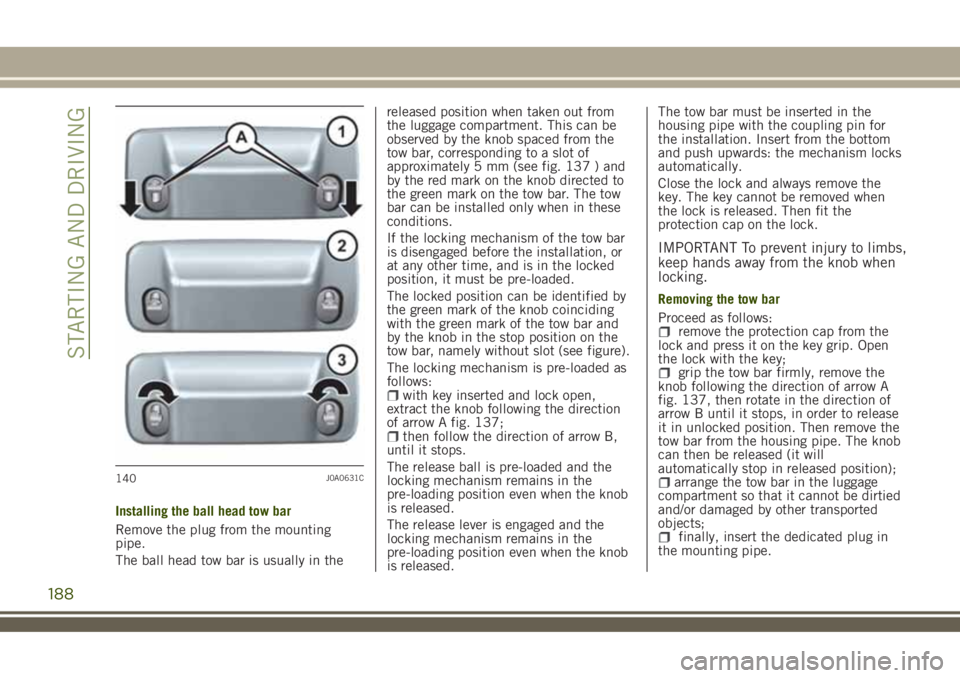
and slide it downwards (2) to remove it.Trim refitting: move devices A
fig. 140 downwards then turn them
90° towards the inside, as indicated by
the arrows.
138J0A0628C
139J0A0627C
187
Page 190 of 356
Installing the ball head tow bar
Remove the plug from the mounting
pipe.
The ball head tow bar is usually in thereleased position when taken out from
the luggage compartment. This can be
observed by the knob spaced from the
tow bar, corresponding to a slot of
approximately 5 mm (see fig. 137 ) and
by the red mark on the knob directed to
the green mark on the tow bar. The tow
bar can be installed only when in these
conditions.
If the locking mechanism of the tow bar
is disengaged before the installation, or
at any other time, and is in the locked
position, it must be pre-loaded.
The locked position can be identified by
the green mark of the knob coinciding
with the green mark of the tow bar and
by the knob in the stop position on the
tow bar, namely without slot (see figure).
The locking mechanism is pre-loaded as
follows:
with key inserted and lock open,
extract the knob following the direction
of arrow A fig. 137;
then follow the direction of arrow B,
until it stops.
The release ball is pre-loaded and the
locking mechanism remains in the
pre-loading position even when the knob
is released.
The release lever is engaged and the
locking mechanism remains in the
pre-loading position even when the knob
is released.The tow bar must be inserted in the
housing pipe with the coupling pin for
the installation. Insert from the bottom
and push upwards: the mechanism locks
automatically.
Close the lock and always remove the
key. The key cannot be removed when
the lock is released. Then fit the
protection cap on the lock.
IMPORTANT To prevent injury to limbs,
keep hands away from the knob when
locking.
Removing the tow bar
Proceed as follows:
remove the protection cap from the
lock and press it on the key grip. Open
the lock with the key;
grip the tow bar firmly, remove the
knob following the direction of arrow A
fig. 137, then rotate in the direction of
arrow B until it stops, in order to release
it in unlocked position. Then remove the
tow bar from the housing pipe. The knob
can then be released (it will
automatically stop in released position);
arrange the tow bar in the luggage
compartment so that it cannot be dirtied
and/or damaged by other transported
objects;
finally, insert the dedicated plug in
the mounting pipe.
140J0A0631C
188
STARTING AND DRIVING