warning JEEP RENEGADE 2018 Owner handbook (in English)
[x] Cancel search | Manufacturer: JEEP, Model Year: 2018, Model line: RENEGADE, Model: JEEP RENEGADE 2018Pages: 356, PDF Size: 6.11 MB
Page 55 of 356
24) 25)
CLOSING
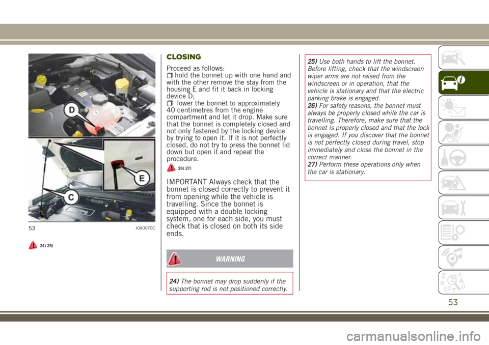
Proceed as follows:hold the bonnet up with one hand and
with the other remove the stay from the
housing E and fit it back in locking
device D;
lower the bonnet to approximately
40 centimetres from the engine
compartment and let it drop. Make sure
that the bonnet is completely closed and
not only fastened by the locking device
by trying to open it. If it is not perfectly
closed, do not try to press the bonnet lid
down but open it and repeat the
procedure.
26) 27)
IMPORTANT Always check that the
bonnet is closed correctly to prevent it
from opening while the vehicle is
travelling. Since the bonnet is
equipped with a double locking
system, one for each side, you must
check that is closed on both its side
ends.
WARNING
24)The bonnet may drop suddenly if the
supporting rod is not positioned correctly.25)Use both hands to lift the bonnet.
Before lifting, check that the windscreen
wiper arms are not raised from the
windscreen or in operation, that the
vehicle is stationary and that the electric
parking brake is engaged.
26)For safety reasons, the bonnet must
always be properly closed while the car is
travelling. Therefore, make sure that the
bonnet is properly closed and that the lock
is engaged. If you discover that the bonnet
is not perfectly closed during travel, stop
immediately and close the bonnet in the
correct manner.
27)Perform these operations only when
the car is stationary.
53J0A0070C
53
Page 57 of 356
LUGGAGE COMPARTMENT
INITIALISATION
IMPORTANT If the battery is
disconnected or the protection fuse
blows, the luggage compartment
opening/closing mechanism must be
reinitialised as follows:
close all the doors and the luggage
compartment;
press thebutton on the remote
control;
press thebutton on the remote
control.
LOAD COMPARTMENT FEATURES
Reconfigurable load platform
The platform has two different positions:
the "level with ground" (position "0") or
the "all up" (position "1"). The load
platform can also be poeitioned obliquely
(inclined towards the rear seats) to ease
access to the area beneath the boot.
The load platform can be tipped, and it
comes with a handy washable plastic
covering for carrying wet or muddy items.
13)
Access/moving the reconfigurable load
platform
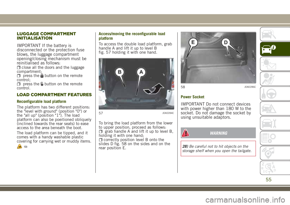
To access the double load platform, grab
handle A and lift it up to level B
fig. 57 holding it with one hand.
To bring the load platform from the lower
to upper position, proceed as follows:
grab handle A and lift it up to level B,
holding it with one hand;
correctly position level B onto the
slides D fig. 58 on the sides and on the
rear position E.Power Socket
IMPORTANT Do not connect devices
with power higher than 180 W to the
socket. Do not damage the socket by
using unsuitable adaptors.
WARNING
28)Be careful not to hit objects on the
storage shelf when you open the tailgate.
57J0A0284C
58J0A0286C
55
Page 60 of 356
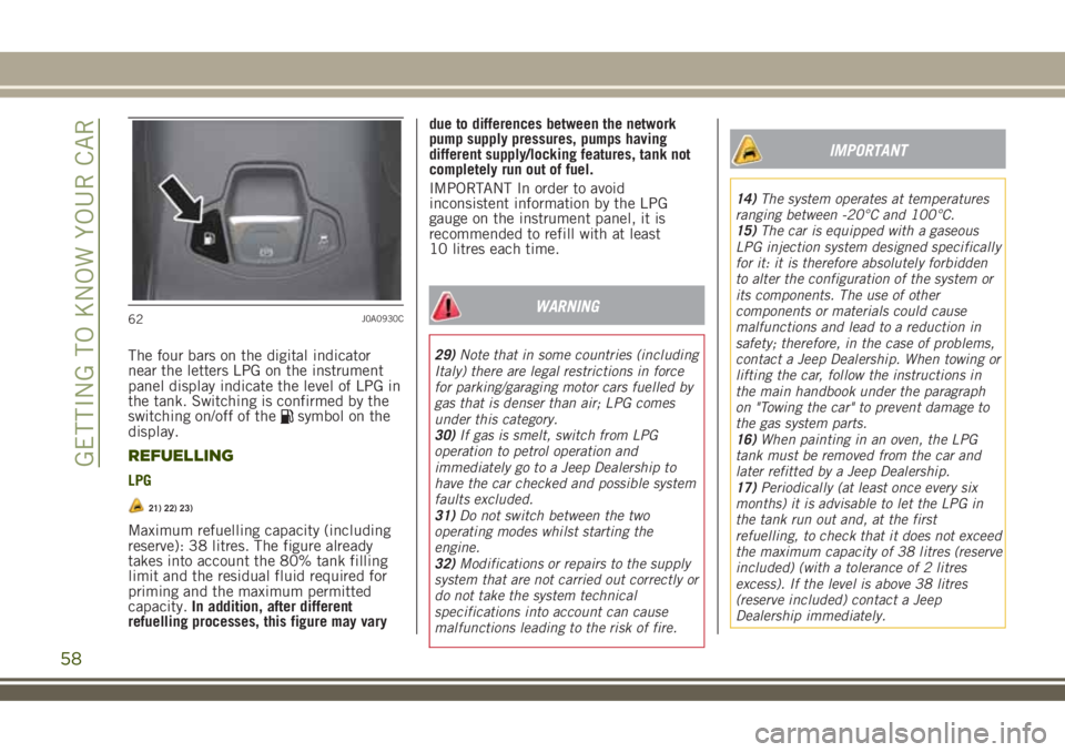
The four bars on the digital indicator
near the letters LPG on the instrument
panel display indicate the level of LPG in
the tank. Switching is confirmed by the
switching on/off of the
symbol on the
display.
REFUELLING
LPG
21) 22) 23)
Maximum refuelling capacity (including
reserve): 38 litres. The figure already
takes into account the 80% tank filling
limit and the residual fluid required for
priming and the maximum permitted
capacity.In addition, after different
refuelling processes, this figure may varydue to differences between the network
pump supply pressures, pumps having
different supply/locking features, tank not
completely run out of fuel.
IMPORTANT In order to avoid
inconsistent information by the LPG
gauge on the instrument panel, it is
recommended to refill with at least
10 litres each time.
WARNING
29)Note that in some countries (including
Italy) there are legal restrictions in force
for parking/garaging motor cars fuelled by
gas that is denser than air; LPG comes
under this category.
30)If gas is smelt, switch from LPG
operation to petrol operation and
immediately go to a Jeep Dealership to
have the car checked and possible system
faults excluded.
31)Do not switch between the two
operating modes whilst starting the
engine.
32)Modifications or repairs to the supply
system that are not carried out correctly or
do not take the system technical
specifications into account can cause
malfunctions leading to the risk of fire.
IMPORTANT
14)The system operates at temperatures
ranging between -20°C and 100°C.
15)The car is equipped with a gaseous
LPG injection system designed specifically
for it: it is therefore absolutely forbidden
to alter the configuration of the system or
its components. The use of other
components or materials could cause
malfunctions and lead to a reduction in
safety; therefore, in the case of problems,
contact a Jeep Dealership. When towing or
lifting the car, follow the instructions in
the main handbook under the paragraph
on "Towing the car" to prevent damage to
the gas system parts.
16)When painting in an oven, the LPG
tank must be removed from the car and
later refitted by a Jeep Dealership.
17)Periodically (at least once every six
months) it is advisable to let the LPG in
the tank run out and, at the first
refuelling, to check that it does not exceed
the maximum capacity of 38 litres (reserve
included) (with a tolerance of 2 litres
excess). If the level is above 38 litres
(reserve included) contact a Jeep
Dealership immediately.
62J0A0930C
58
GETTING TO KNOW YOUR CAR
Page 63 of 356
KNOWING THE INSTRUMENT PANEL
This section of the booklet gives you all
the information you need to understand,
interpret and use the instrument panel
correctly.EOBD SYSTEM (European On Board
Diagnosis)..................62
CONTROL PANEL AND ON-BOARD
INSTRUMENTS..............63
DISPLAY...................67
TRIP COMPUTER.............70
WARNING LIGHTS AND MESSAGES .71
61
Page 64 of 356
EOBD SYSTEM (European
On Board Diagnosis)
(where provided)
OPERATION
The EOBD system (European On Board
Diagnosis) carries out a continuous
diagnosis of the components of the car
related to emissions.
It also alerts the driver, by switching on
the
warning light on the instrument
panel, together with a message on the
display, when these components are no
longer in peak condition (see “Warning
lights and messages” paragraph in this
chapter).
The aim of the EOBD system (European
On Board Diagnosis) is to:
monitor the efficiency of the system;indicate an increase in emissions;indicate the need to replace damaged
components.
The vehicle also has a connector, which
can interface with appropriate tools, that
makes it possible to read the error codes
stored in the electronic control units
together with a series of specific
parameters for engine operation and
diagnosis. This check can also be carried
out by the traffic police.
IMPORTANT After eliminating a fault,
to check the system completely, a Jeep
Dealership is obliged to run tests and,
if necessary, road tests which may also
require a long journey.
62
KNOWING THE INSTRUMENT PANEL
Page 65 of 356
CONTROL PANEL AND ON-BOARD INSTRUMENTS
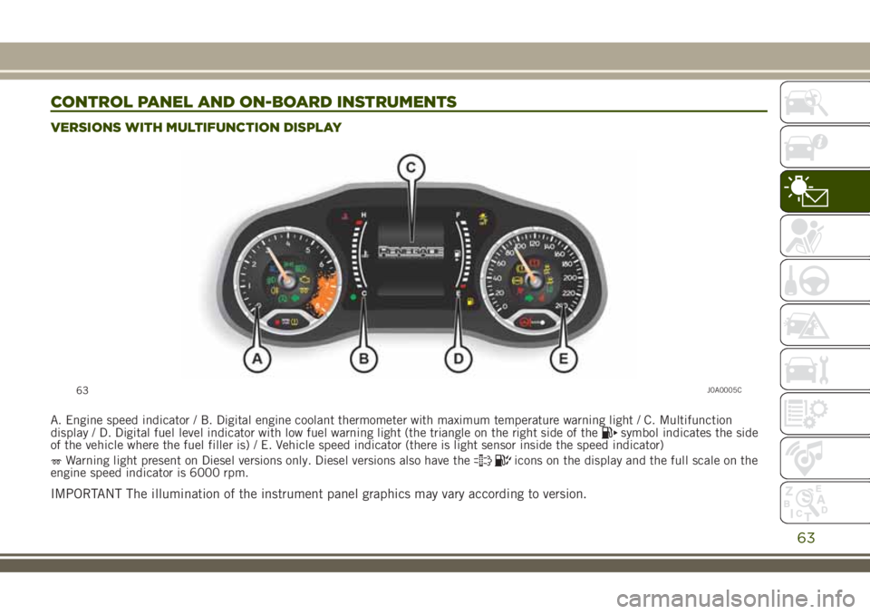
VERSIONS WITH MULTIFUNCTION DISPLAY
A. Engine speed indicator / B. Digital engine coolant thermometer with maximum temperature warning light / C. Multifunction
display / D. Digital fuel level indicator with low fuel warning light (the triangle on the right side of thesymbol indicates the side
of the vehicle where the fuel filler is) / E. Vehicle speed indicator (there is light sensor inside the speed indicator)
Warning light present on Diesel versions only. Diesel versions also have theicons on the display and the full scale on the
engine speed indicator is 6000 rpm.
IMPORTANT The illumination of the instrument panel graphics may vary according to version.
63J0A0005C
63
Page 66 of 356
64J0A0239C
64
KNOWING THE INSTRUMENT PANEL
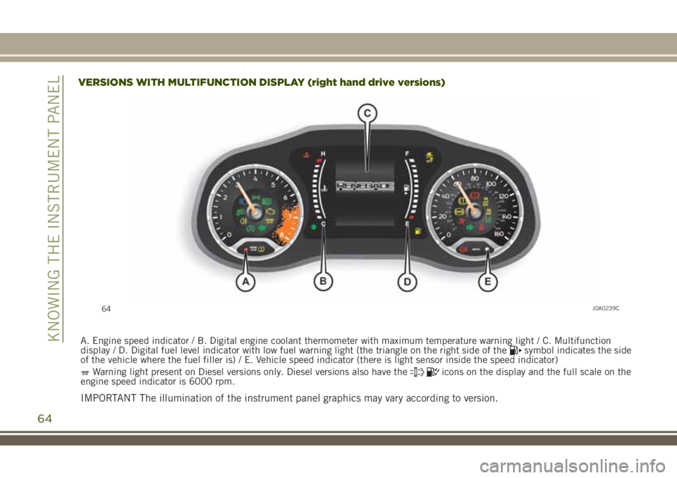
VERSIONS WITH MULTIFUNCTION DISPLAY (right hand drive versions)
A. Engine speed indicator / B. Digital engine coolant thermometer with maximum temperature warning light / C. Multifunction
display / D. Digital fuel level indicator with low fuel warning light (the triangle on the right side of thesymbol indicates the side
of the vehicle where the fuel filler is) / E. Vehicle speed indicator (there is light sensor inside the speed indicator)
Warning light present on Diesel versions only. Diesel versions also have theicons on the display and the full scale on the
engine speed indicator is 6000 rpm.
IMPORTANT The illumination of the instrument panel graphics may vary according to version.
Page 67 of 356
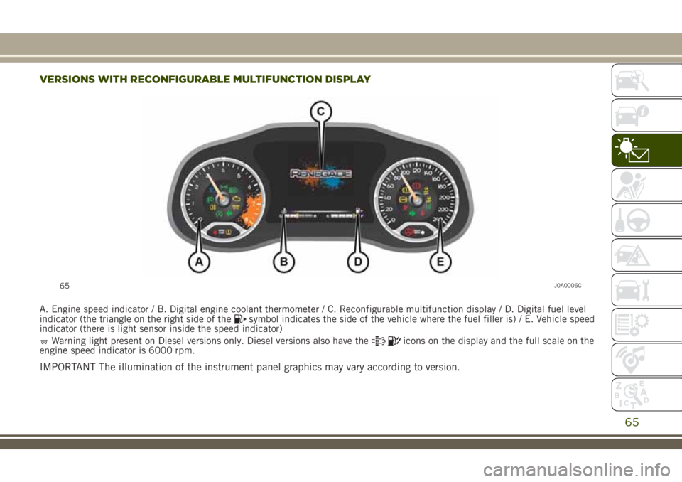
VERSIONS WITH RECONFIGURABLE MULTIFUNCTION DISPLAY
A. Engine speed indicator / B. Digital engine coolant thermometer / C. Reconfigurable multifunction display / D. Digital fuel level
indicator (the triangle on the right side of thesymbol indicates the side of the vehicle where the fuel filler is) / E. Vehicle speed
indicator (there is light sensor inside the speed indicator)
Warning light present on Diesel versions only. Diesel versions also have theicons on the display and the full scale on the
engine speed indicator is 6000 rpm.
IMPORTANT The illumination of the instrument panel graphics may vary according to version.
65J0A0006C
65
Page 68 of 356
66J0A0238C
66
KNOWING THE INSTRUMENT PANEL
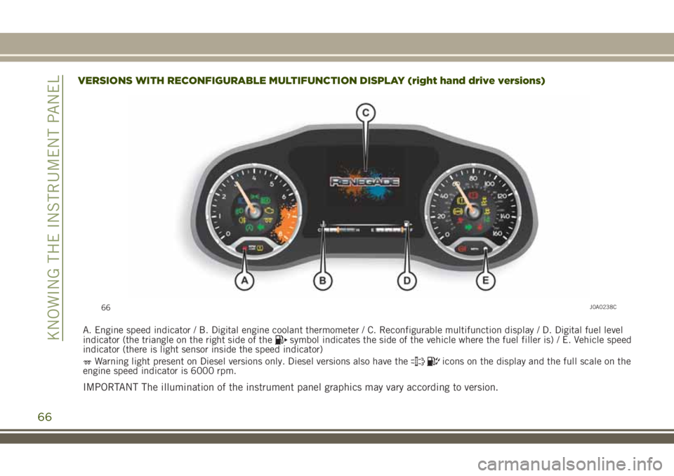
VERSIONS WITH RECONFIGURABLE MULTIFUNCTIONDISPLAY (right hand drive versions)
A. Engine speed indicator / B. Digital engine coolant thermometer / C. Reconfigurable multifunction display / D. Digital fuel level
indicator (the triangle on the right side of thesymbol indicates the side of the vehicle where the fuel filler is) / E. Vehicle speed
indicator (there is light sensor inside the speed indicator)
Warning light present on Diesel versions only. Diesel versions also have theicons on the display and the full scale on the
engine speed indicator is 6000 rpm.
IMPORTANT The illumination of the instrument panel graphics may vary according to version.
Page 69 of 356
DISPLAY
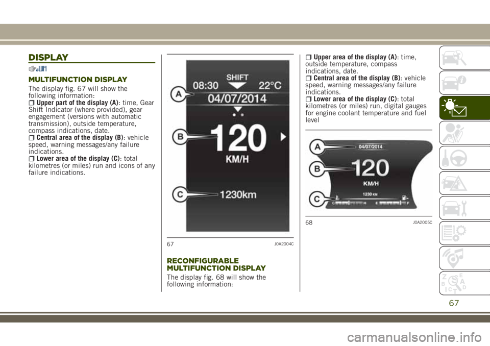
MULTIFUNCTION DISPLAY
The display fig. 67 will show the
following information:
Upper part of the display (A): time, Gear
Shift Indicator (where provided), gear
engagement (versions with automatic
transmission), outside temperature,
compass indications, date.
Central area of the display (B): vehicle
speed, warning messages/any failure
indications.
Lower area of the display (C): total
kilometres (or miles) run and icons of any
failure indications.
RECONFIGURABLE
MULTIFUNCTION DISPLAY
The display fig. 68 will show the
following information:
Upper area of the display (A): time,
outside temperature, compass
indications, date.
Central area of the display (B): vehicle
speed, warning messages/any failure
indications.
Lower area of the display (C): total
kilometres (or miles) run, digital gauges
for engine coolant temperature and fuel
level
67J0A2004C
68J0A2005C
67